 Arnov Sharma
-
1The Concept of Reflow Soldering
![]()
![]()
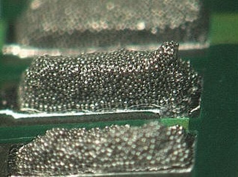
Reflow soldering is a widely used process in electronics manufacturing for soldering surface-mount components to PCBs.
Reflow soldering involves melting solder paste to create a permanent connection between the electrical components and the PCB.
The solder paste is a mixture of small solder particles and flux. The flux serves multiple purposes, including removing any oxide layers on the metal surfaces, promoting wetting, and preventing oxidation during the soldering process.
A precise amount of solder paste is applied to the pads of the components first, and then surface-mount components are placed on the solder paste-covered PCB. The components are positioned based on the design layout
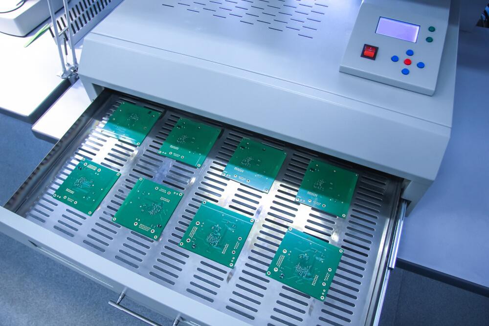
The PCB with components and solder paste is then passed through a reflow oven.
We will be using a reflow hotplate for our case. A reflow oven and a reflow hotplate are fundamentally different from one another; an oven is enclosed, while a hotplate is open. Hotplates are used for circuit rework, whereas reflow ovens are used for professional work, such as in SMD circuit production lines.
-
2Existing Hotplate
![]()
![]()
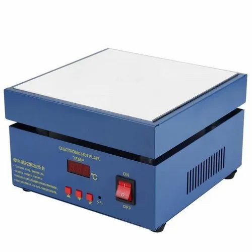
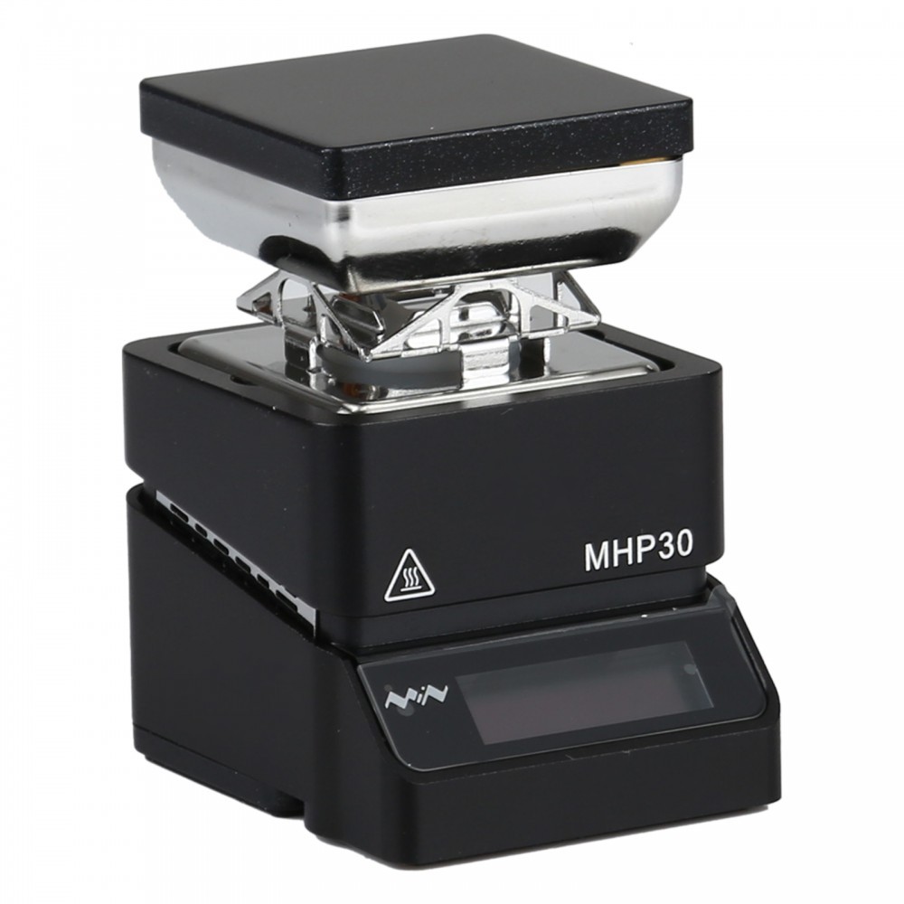
There are already hotplates on the market with more useful features like cutoff features, manual temperature control, strong bodies, etc.
Every size of these hotplates is available. A common example of a small hotplate is the Miniware MHP30, whose reflow surface measures only 30 by 30 mm, making it ideal for reflowing smaller PCBs.
The only drawback of these hotplates is their price, which can be expensive for a beginner. However, one solution to this problem is to create a do-it-yourself hotplate that functions similarly to the original.
-
3Circuit
![]()
![]()
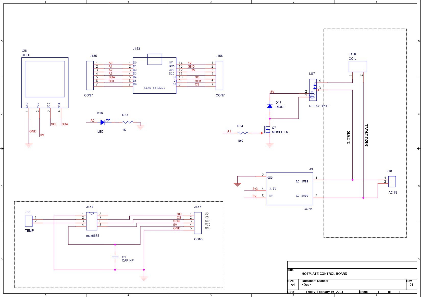
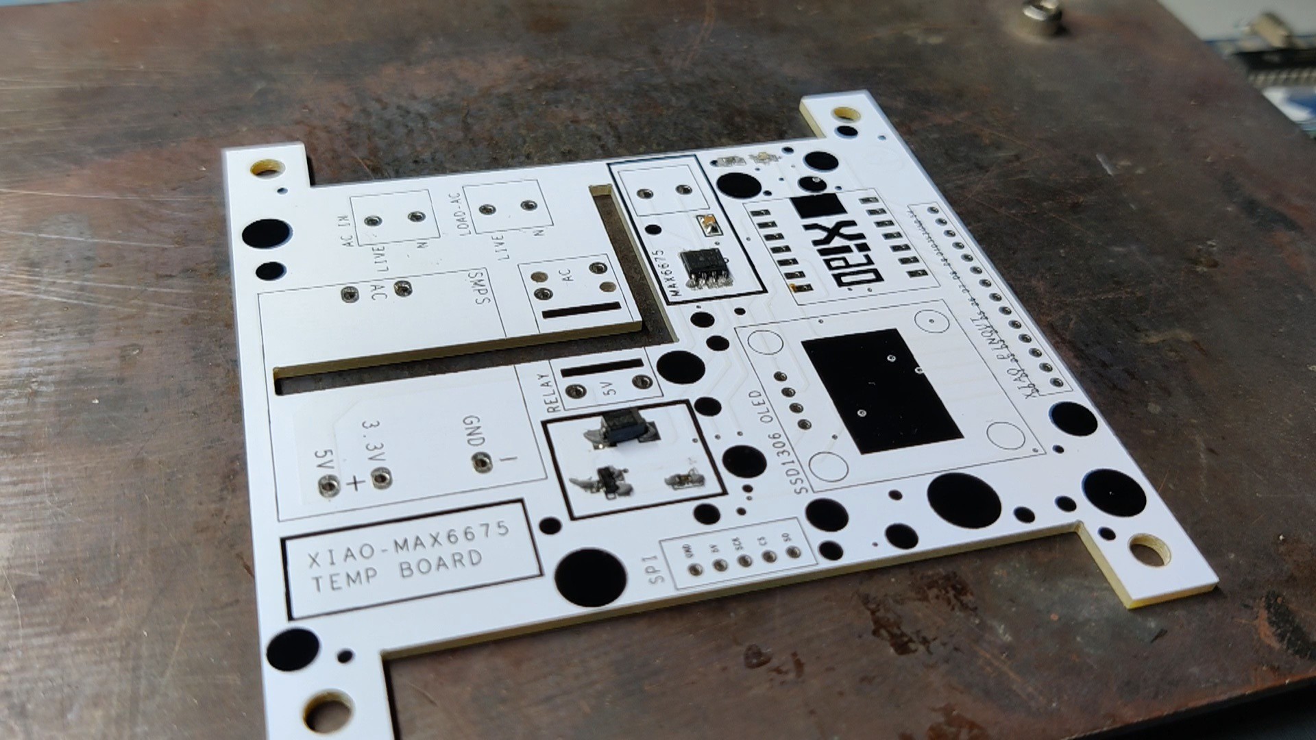
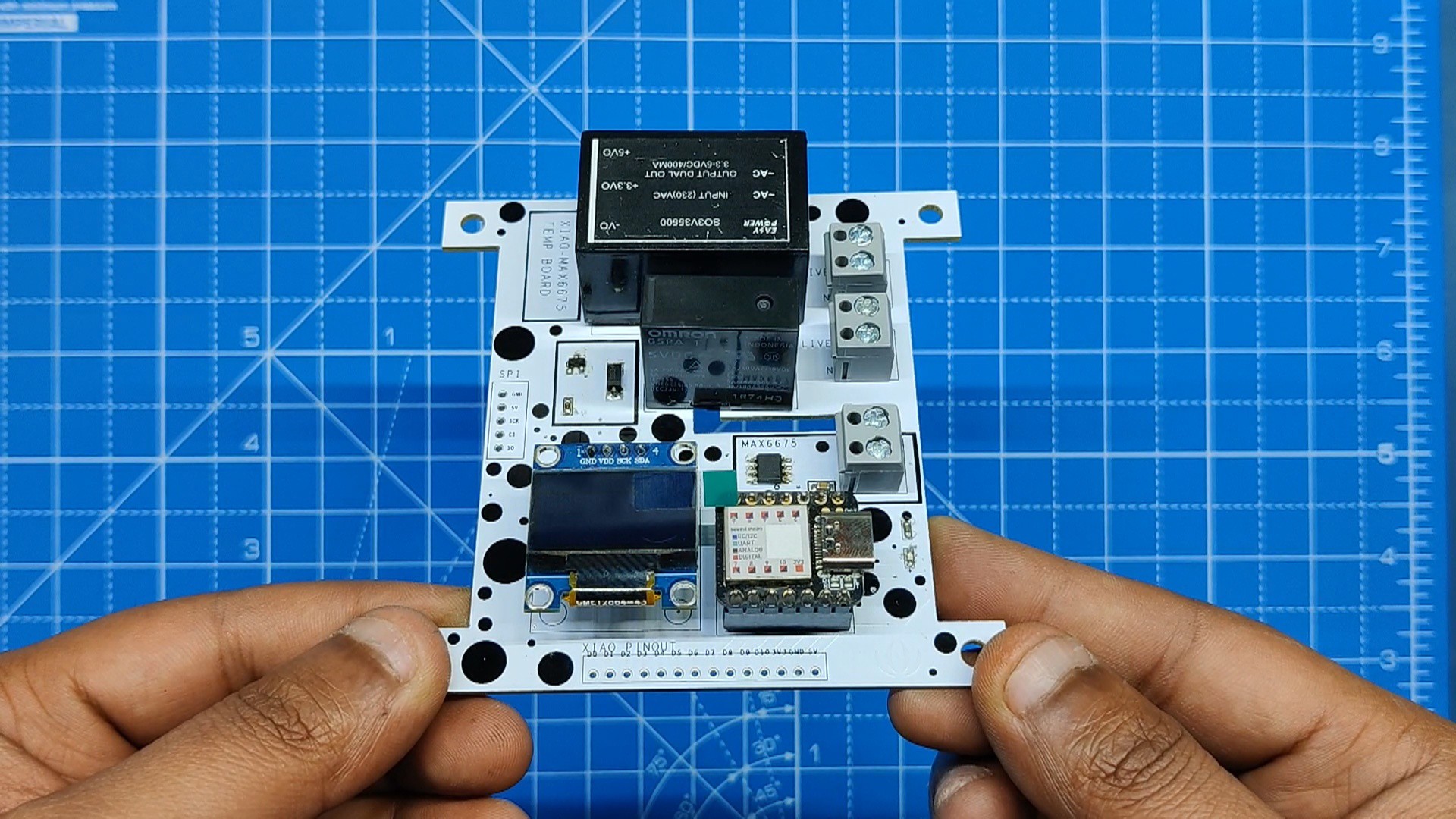
Let us now analyze the main control circuit.
Three sections make up this circuit: the XIAO M0 Microcontroller section, the MAX6675 Setup, and the AC section, which is connected to an isolated SMPS and relay.
Let us begin with the primary part of this circuit, the XIAO M0 DEV Board, which is linked to the SSD1306 display via I2C. Furthermore, the MAX6675 Sensor setup and the relay are linked to the XIAO.
We used a straightforward Mosfet switch configuration, whose gate is controlled by the XIAO M0 DEV Board, to control the relay. Mosfet is the relay's driver.
Our MAX6675 IC gathers temperature measurements and sends them to the XIAO M0 DEV Board. The XIAO Microcontroller then uses the temperature readings to regulate the mosfet's gate, which ON and OFF switches the relay.
One end of the relay is linked to live AC on the AC side, and the other end is attached to a CON2 screw terminal, whose pin 2 is connected to AC neutral. The relay in this configuration acts as a switch between the heating coil and the AC power source.
In order to power the microcontroller and sensor from direct AC, we utilized an isolated power supply module that converts 240V of AC power into 5V and 3.3V.
Additionally, we have added an LED with the I/O pin of the XIAO MCU. This LED will show if the relay is turned on or off by copying the relay state.
After finalizing the PCB schematic, we generated a netlist and prepared the PCB design. For further isolation, we have added a slot between the AC and DC sides.
-
4Seeed Fusion
![]()
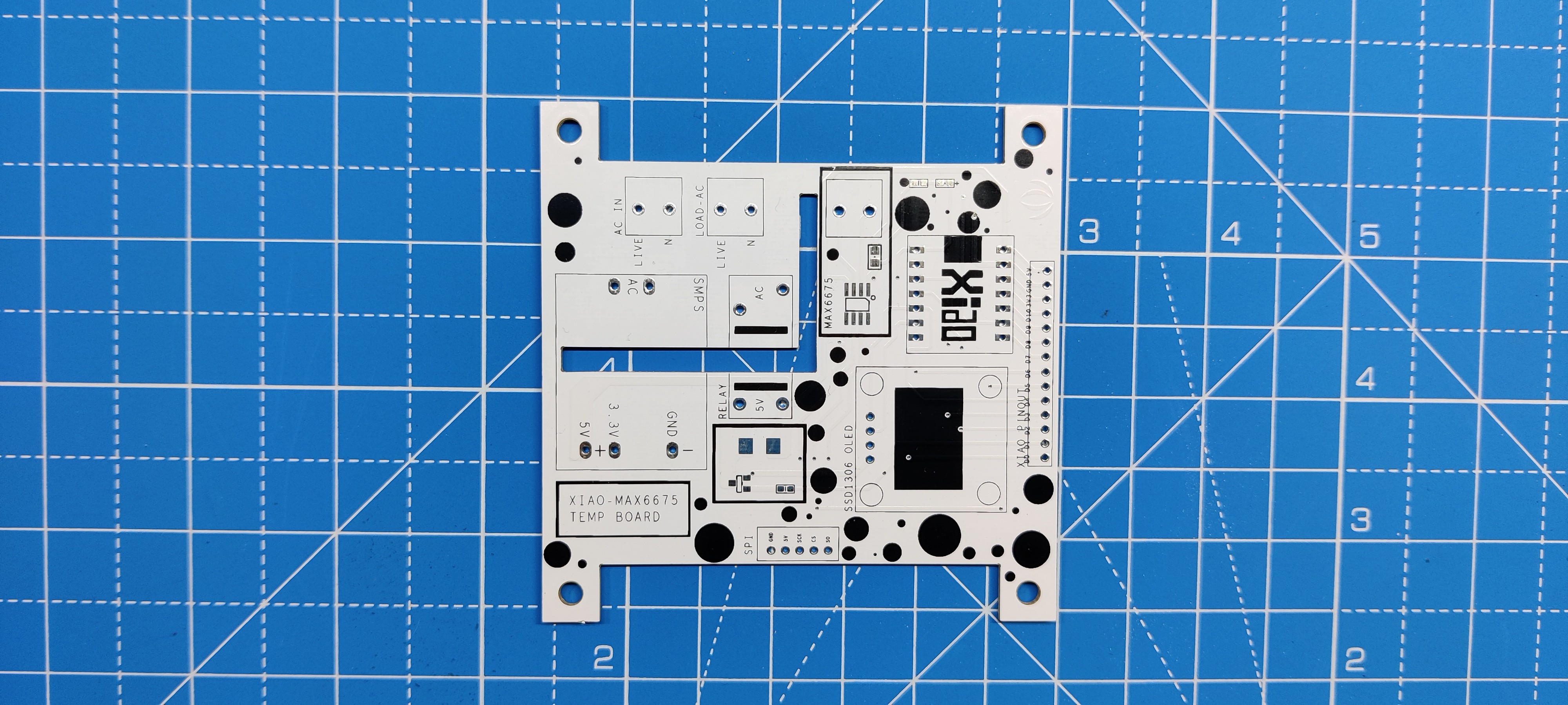
After finalizing the PCB and generating its Gerber data, it was sent it to SEEED Studio for samples.
The PCB was ordered in a white solder mask with black silkscreen.
PCBs were received in a week, and their quality was super good considering the rate, which was also pretty low.
Seeed Fusion PCB Service offers one-stop prototyping for PCB manufacture and PCB assembly, and as a result, they produce superior-quality PCBs and fast turnkey PCBAs within 7 working days.
Seeed Studio Fusion PCB Assembly Service takes care of the entire fabrication process, from Seeed Studio Fusion Agile manufacturing and hardware customization to parts sourcing, assembly, and testing services, so you can be sure that they are getting a quality product.
After gauging market interest and verifying a working prototype, Seeed Propagate Service can help you bring the product to market with professional guidance and a strong network of connections.
Next is the PCB assembly process.
-
5PCB Assembly Process
![]()
![]()
![]()
![]()
![]()
![]()
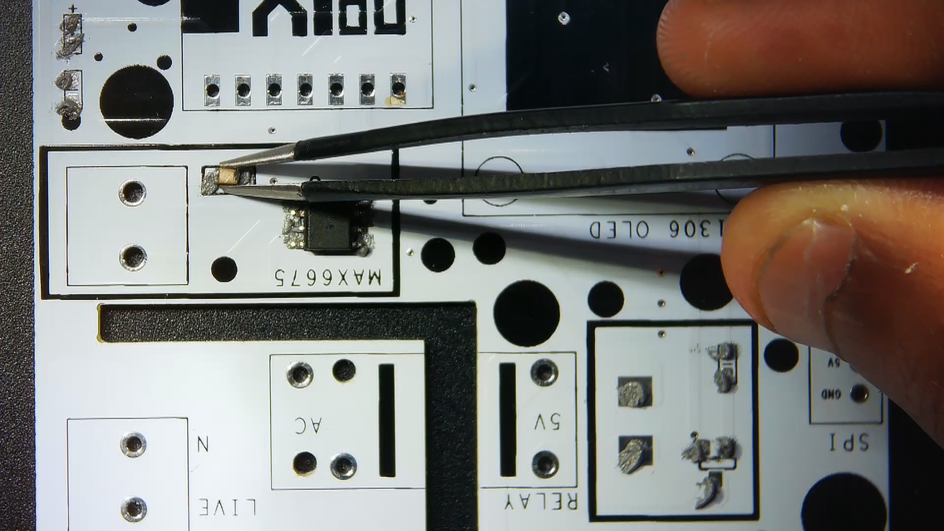
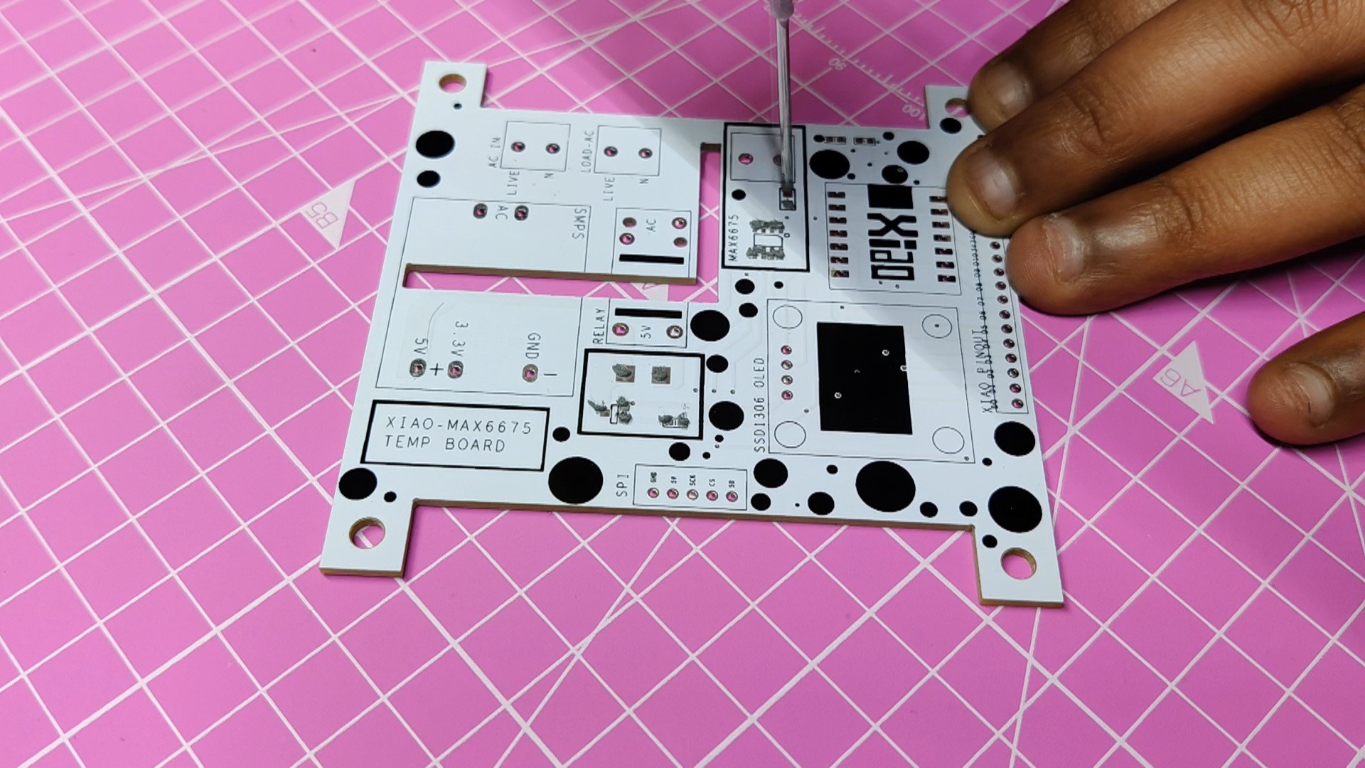
- Using a solder paste dispensing needle, we first add solder paste to each component pad individually to begin the PCB assembly process. In this instance, we are using standard 37/63 solder paste.
- Next, we pick and place all the SMD components in their places on the PCB using an ESD tweezer.
- With extreme caution, we lifted the complete circuit board and placed it on the SMT hotplate, which increases the PCB's temperature to the point at which the solder paste melts and all of the components are connected to their pads.
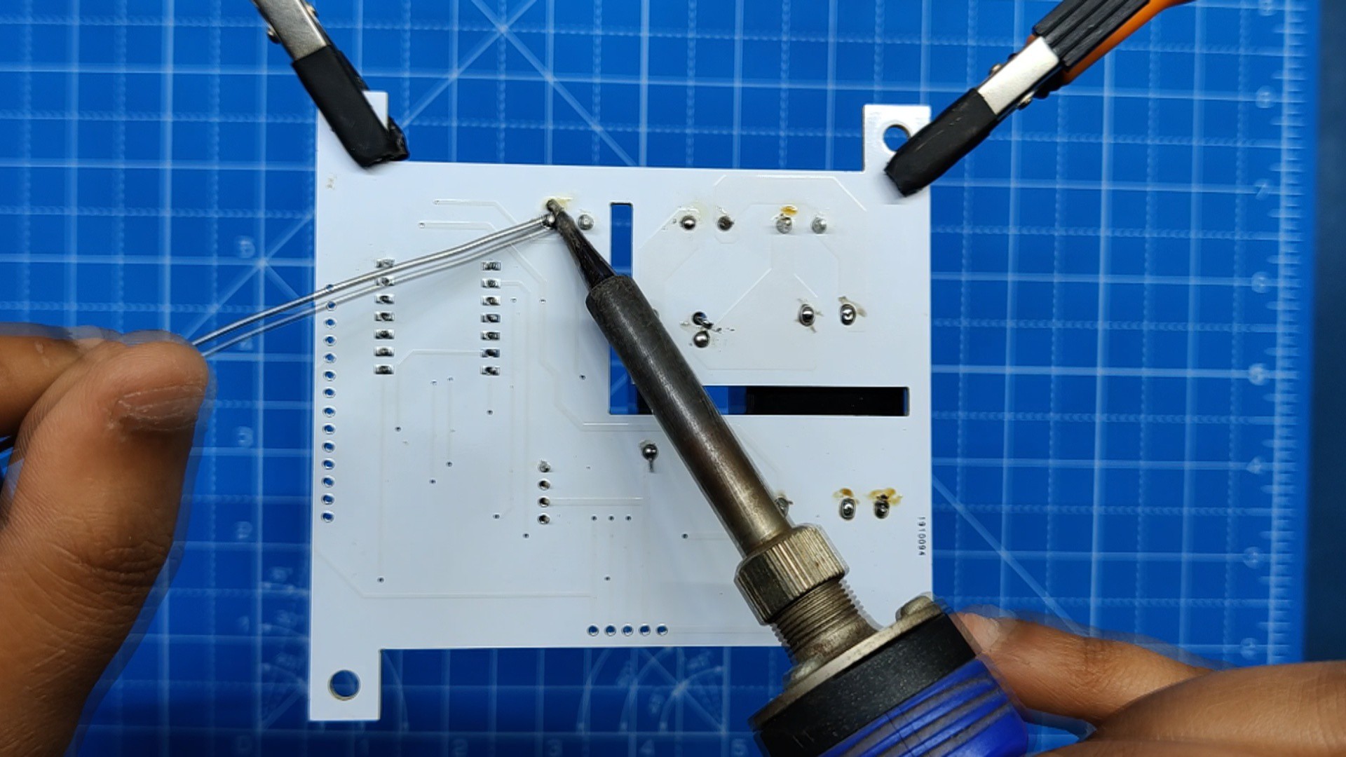
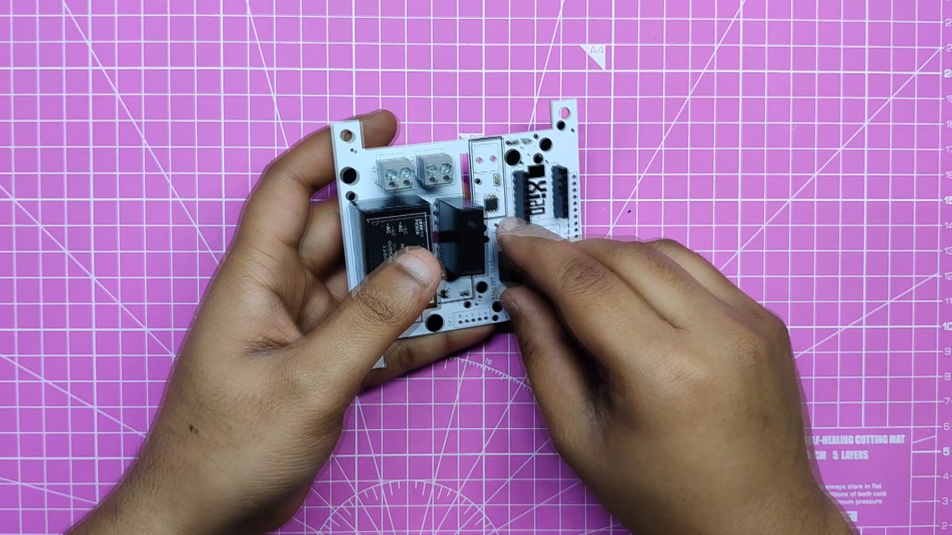
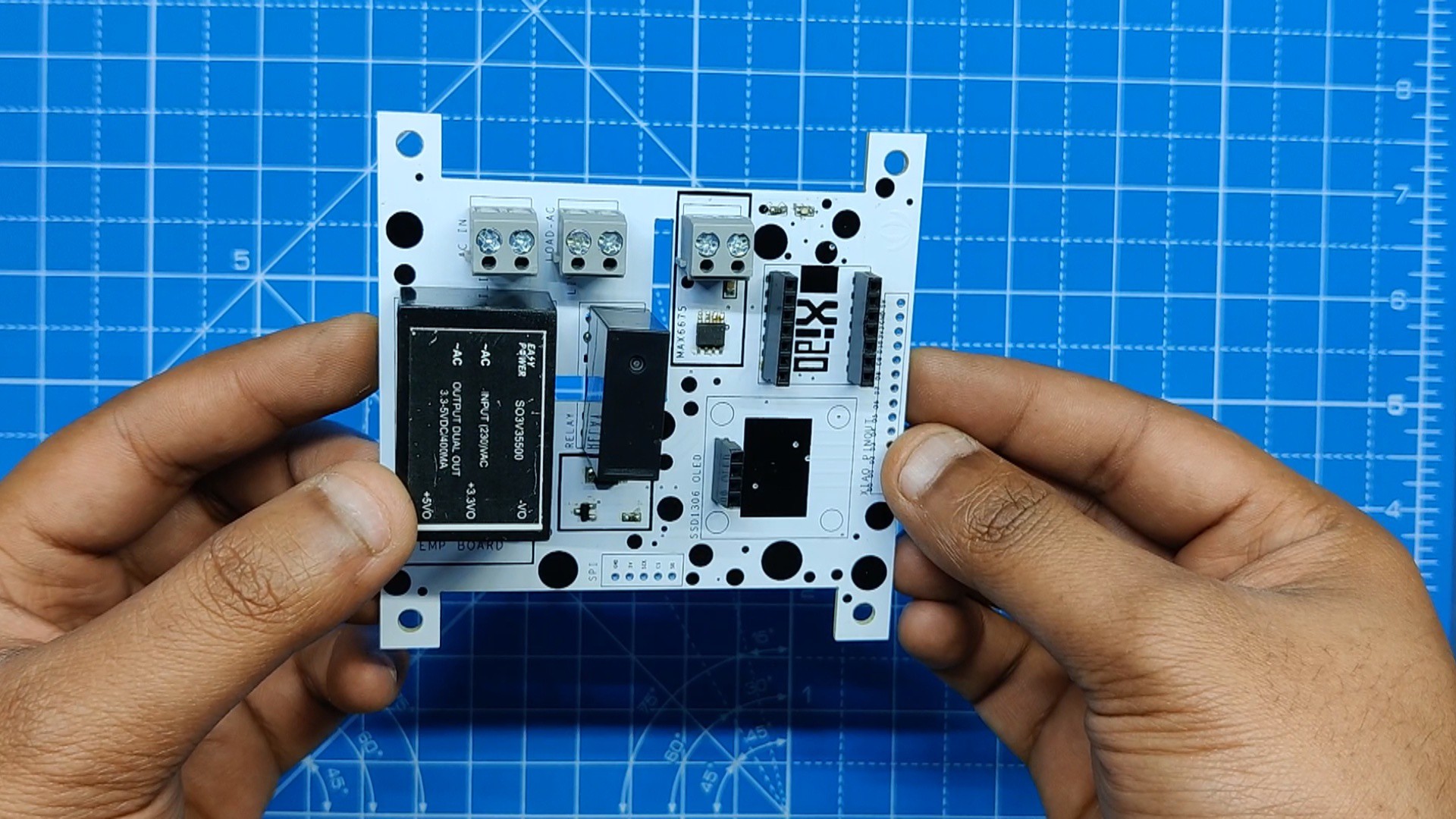
- Next, we add all the THT components, which include the relay, header pin, CON2 screw terminals, and isolated power supply, to their locations and then solder their pads using a soldering iron.
-
6RESULT SO FAR
![]()
![]()
![]()
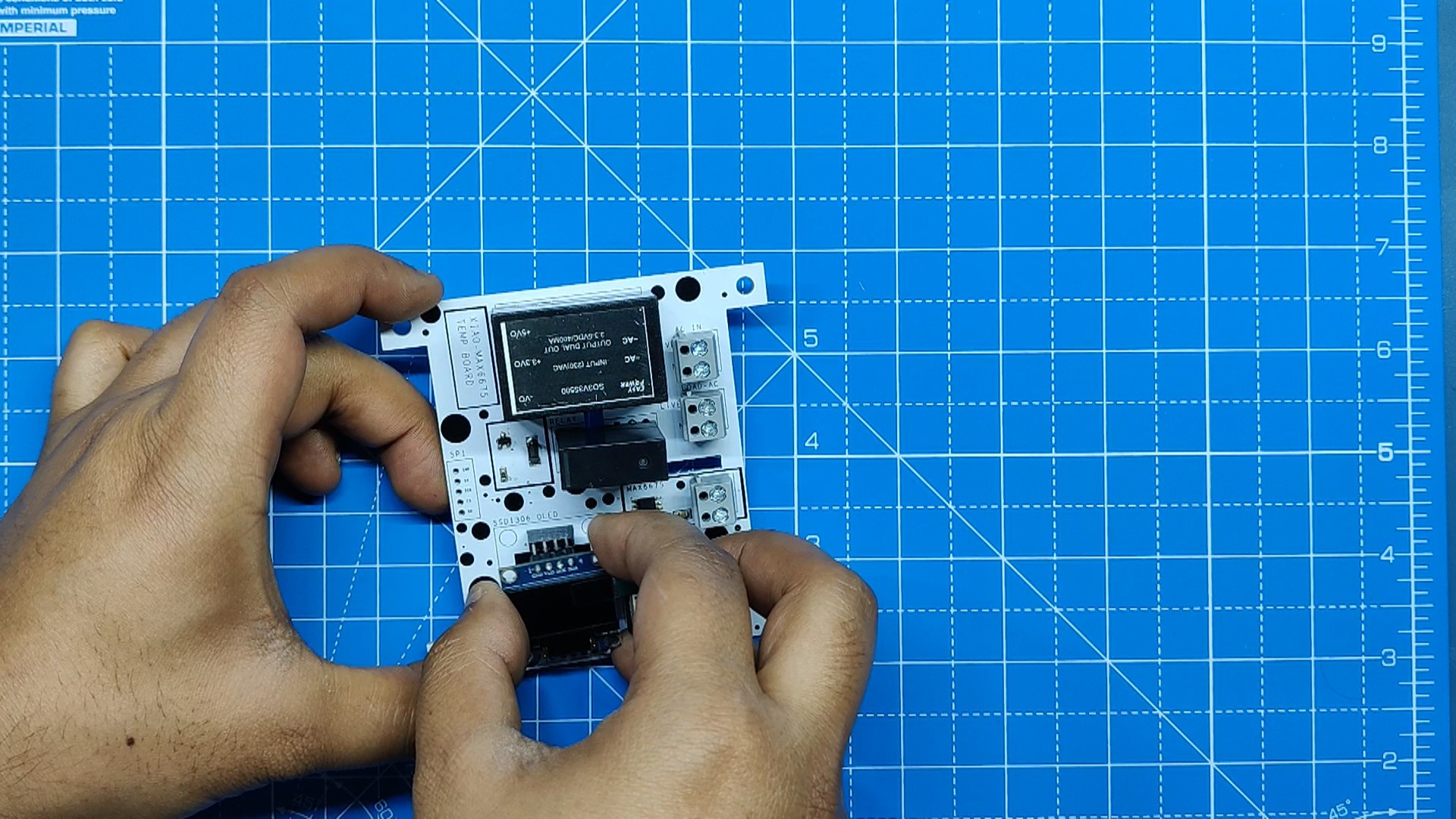
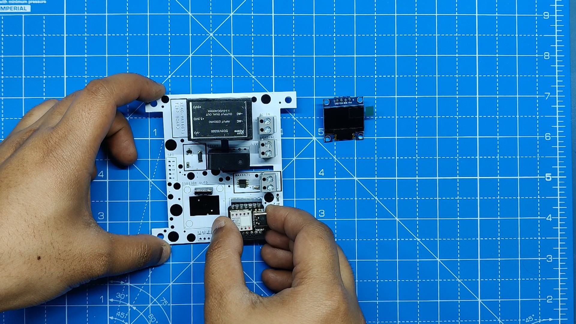
This is the finished circuit with all of the THT and SMD parts mounted to the PCB.
Next, we install the SSD1306 display after positioning the XIAO M0 DEV board into the header pins.
-
7Adding type-K thermocouple
![]()
![]()
![]()
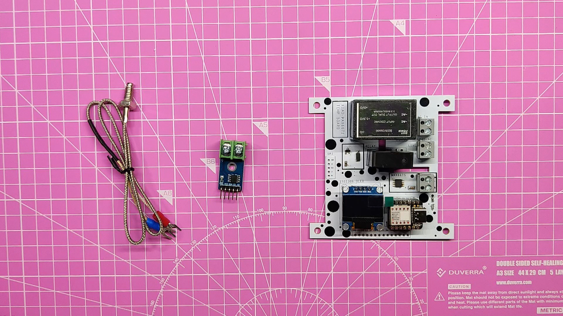
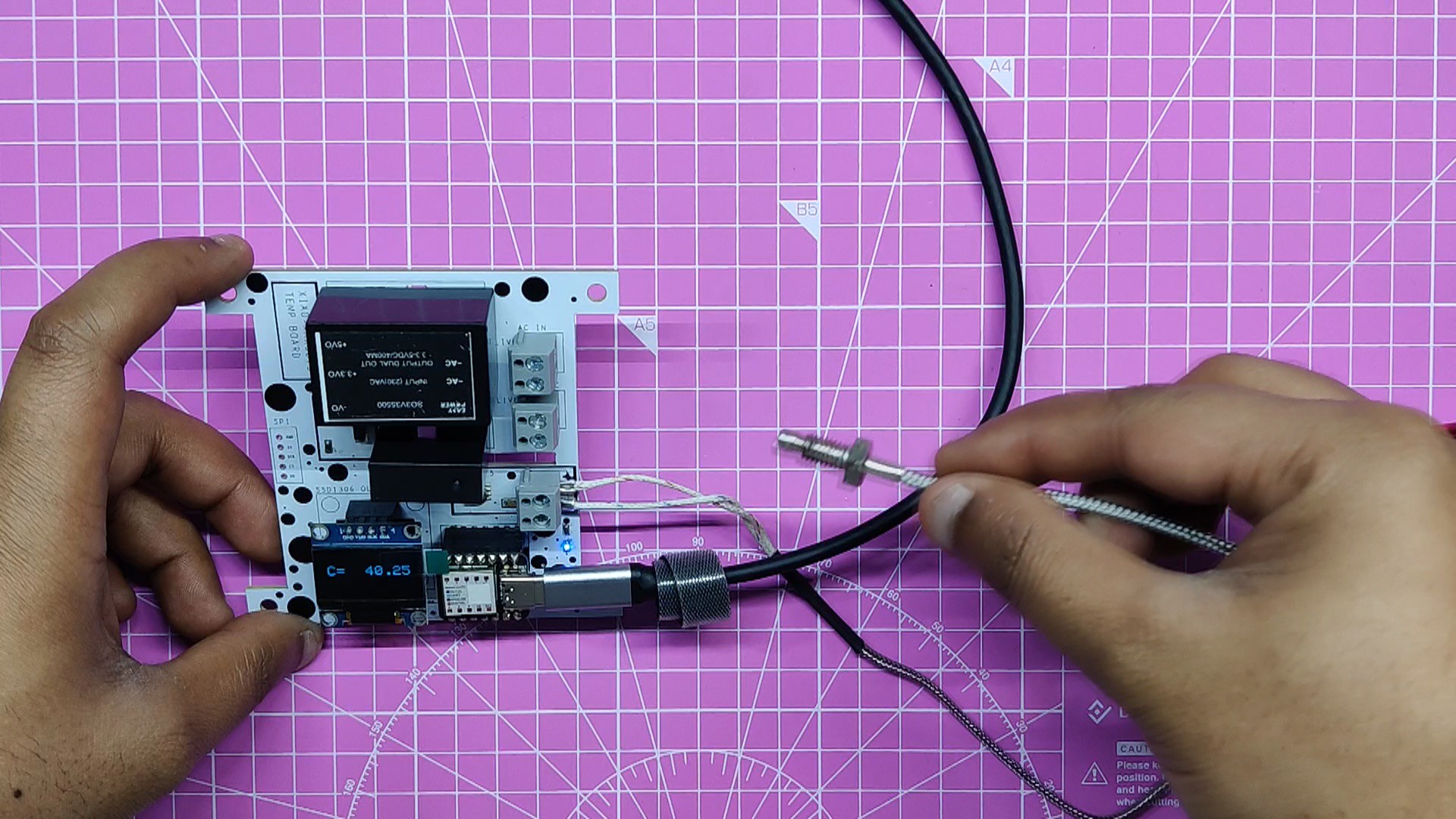
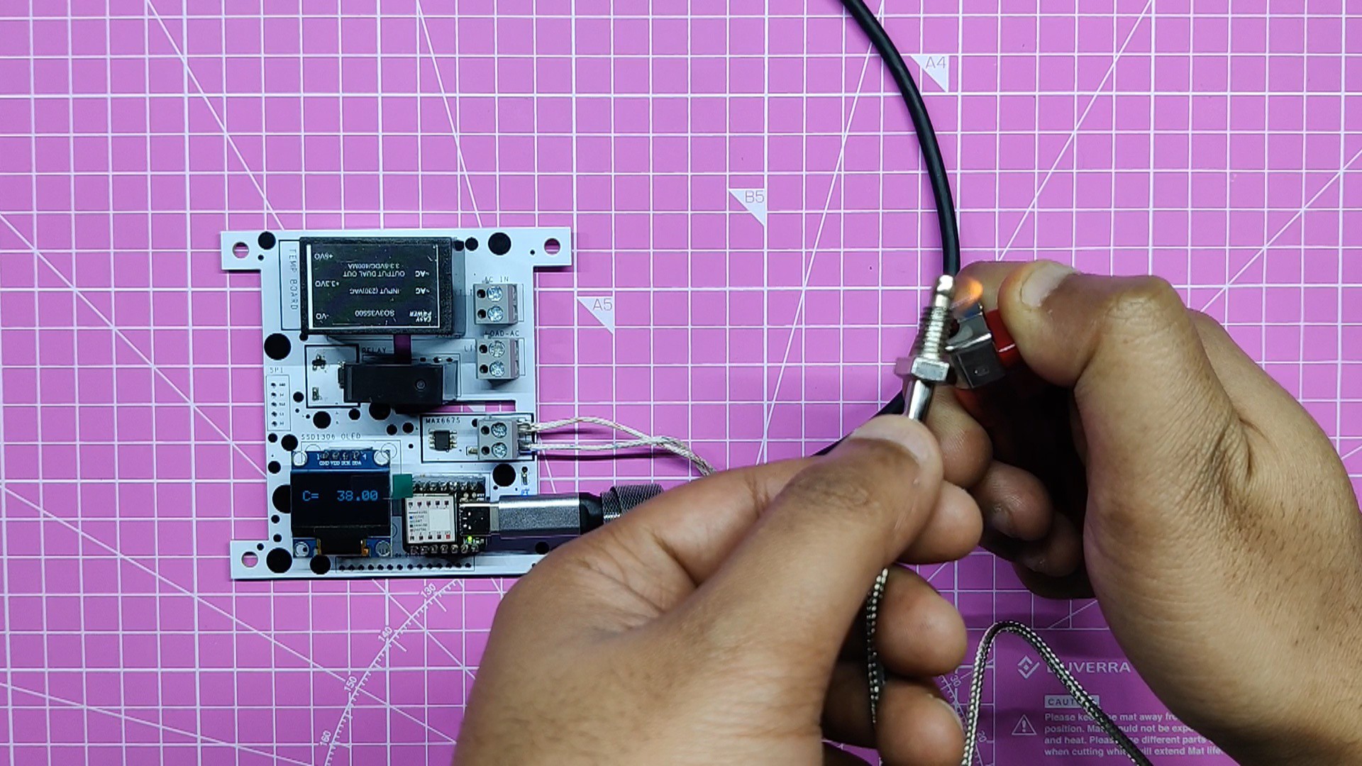
Following circuit completion, we connected the K-type Thermistor supplied by the MAX6675 module to the MAX6675 IC's CON2 screw connection.
In order to test the circuit, we heat the temperature sensor with a lighter and set the threshold to 40°C. The LED turns off when the temperature rises beyond 40°C and reconnects when the temperature falls below 40°C.
-
8CODE
Here's the code used in this build:
const int LED = 0; const int threshold = 150;//cuttoff temp MAX6675 thermocouple(thermoCLK, thermoCS, thermoDO); void setup() { display.begin(SSD1306_SWITCHCAPVCC, OLED_ADDR); pinMode(RelayPin, OUTPUT); pinMode(LED, OUTPUT); Serial.println("MAX6675 test"); // wait for MAX chip to stabilize delay(500); display.clearDisplay(); Serial.begin(9600); } void loop() { // basic readout test, just print the current temp display.setTextSize(2); display.setTextColor(WHITE); display.setCursor(10, 20); display.println("C= "); display.setTextSize(2); display.setTextColor(WHITE); display.setCursor(60, 20); display.println(thermocouple.readCelsius()); display.display(); display.clearDisplay(); delay(300); if (thermocouple.readCelsius() > threshold) { digitalWrite(RelayPin, LOW); digitalWrite(LED, LOW); } else { digitalWrite(RelayPin, HIGH); digitalWrite(LED, HIGH); } // For the MAX6675 to update, you must delay AT LEAST 250ms between reads! delay(500); }- The
<b>loop</b>function continuously reads the temperature from the MAX6675 sensor and displays it on the OLED screen. - If the temperature exceeds a defined threshold (
<b>threshold</b>), it turns off the relay and LED; otherwise, it turns them on. - There is a delay of 500 milliseconds between temperature readings.
- The
-
9Previously made Hotplate Project
This was the previous Hotplate project, which expanded the heating area by connecting the cloth iron's element to a copper plate.
![]()
![]()
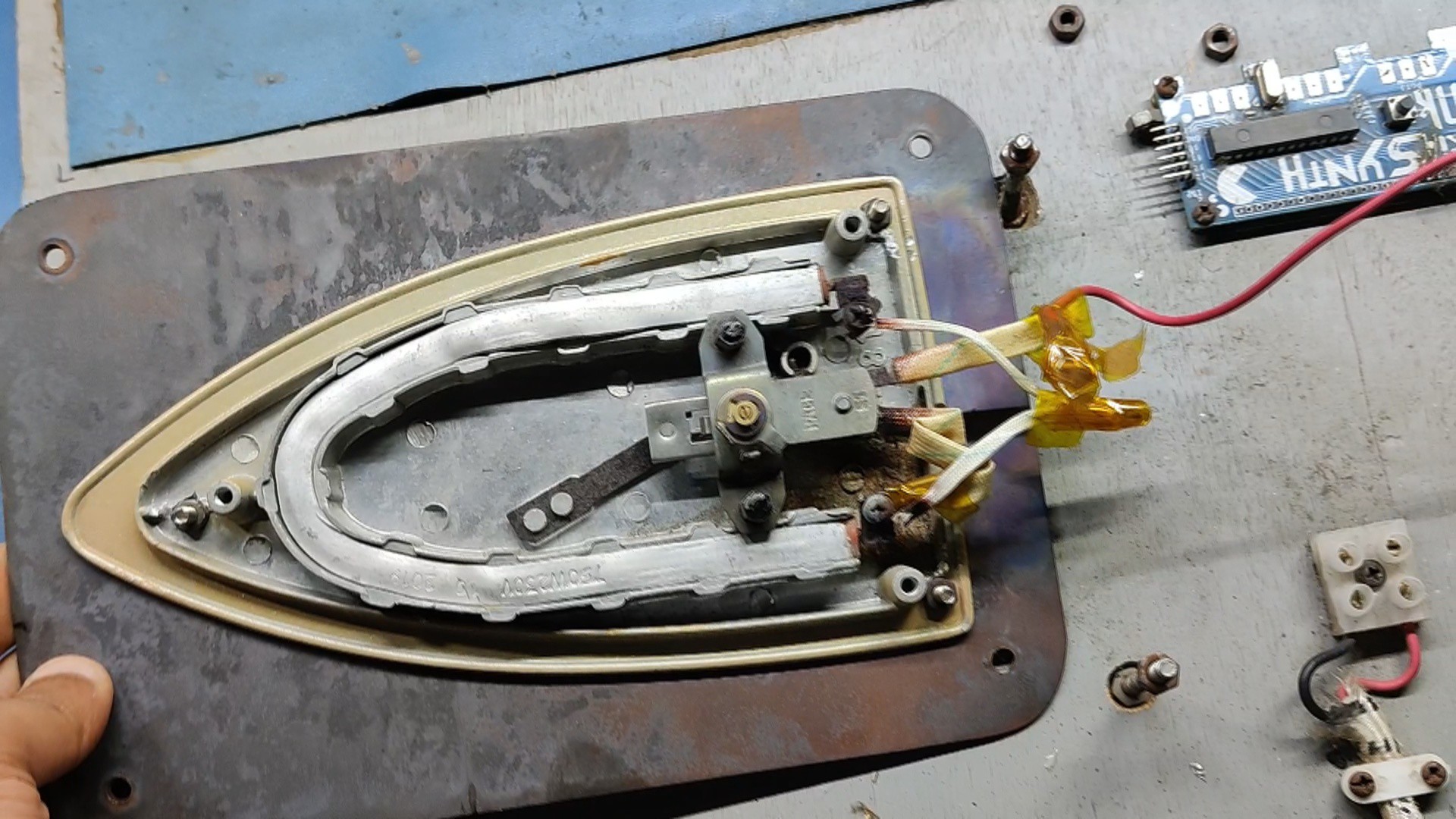
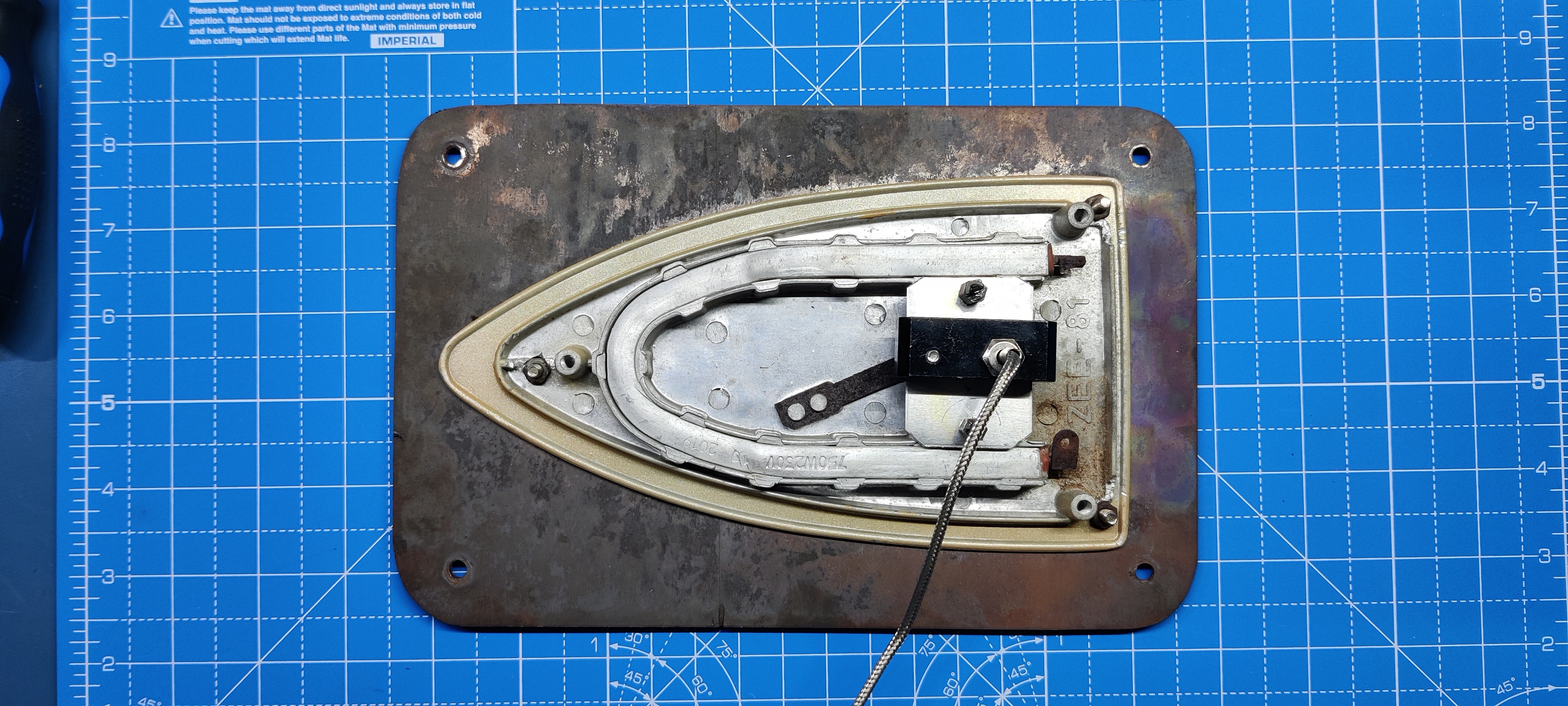
A mechanical mechanism called a thermostat was used to control the heating element of the original version of the hotplate.
The thermostat is an important component of an electric iron that regulates its temperature. When the iron reaches a certain temperature, the thermostat turns off the power of the iron. This mechanism consists of a bimetallic strip that is made from brass and iron. When the temperature of the iron exceeds a certain limit, the strip begins to bend towards the metal with a lower coefficient of expansion. As a result, the strip ceases to be physically connected to the contact point, the circuit opens, and the current ceases to flow.
We're going to use the heating element of Version 1 hotplate in Version 2, but with some major changes.
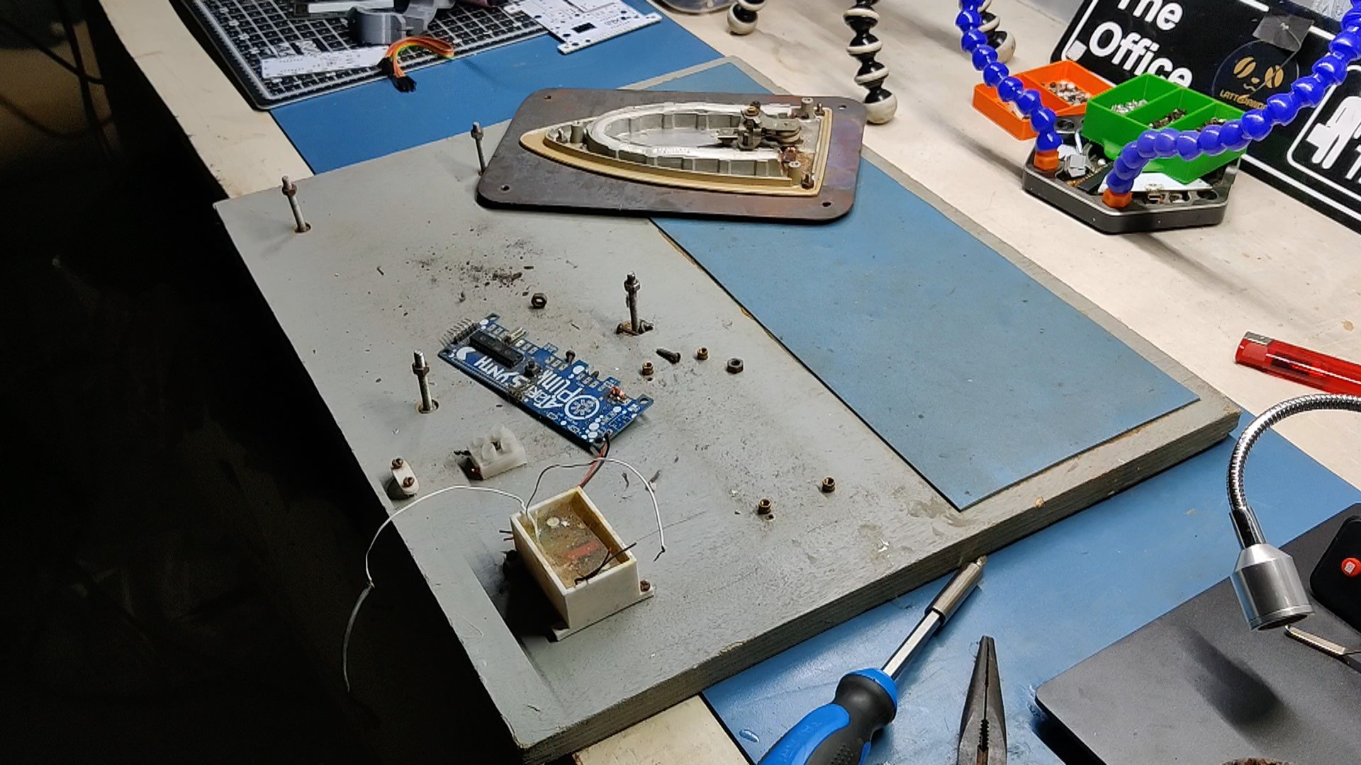
- First, the bolts holding the heating element to the wooden base are unscrewed.
- Next, we unplug the AC supply that was passing through the live and neutral pins of the thermostat and heating element, as well as the thermostat from the heating element.
-
10Adding Thermocouple to Hotplate
![]()
![]()
![]()
![]()
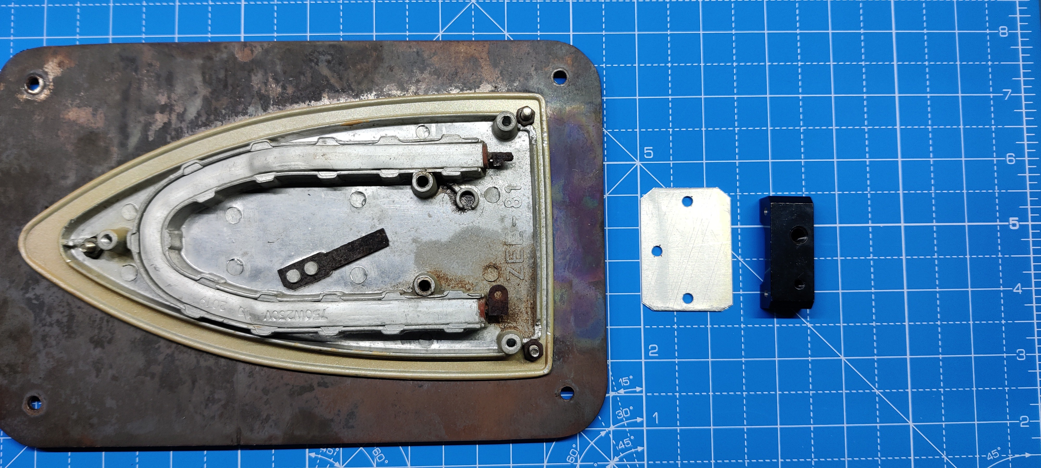
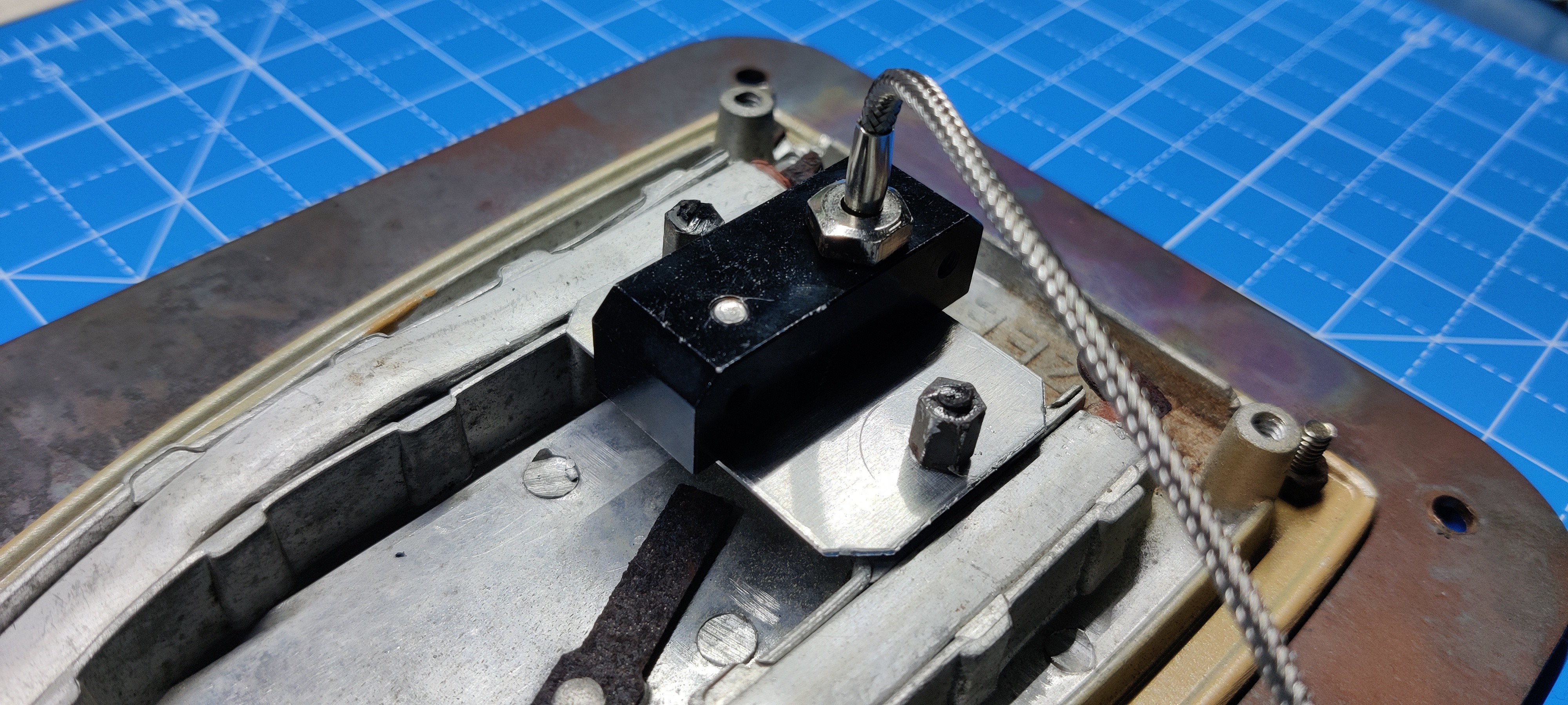
To take temperature readings after removing the mechanical thermostat from the heating element, attach the probe of a K-type thermistor to the surface of the heating element. The closer the thermistor probe is placed to the heating element, the more accurate the measurement will be.
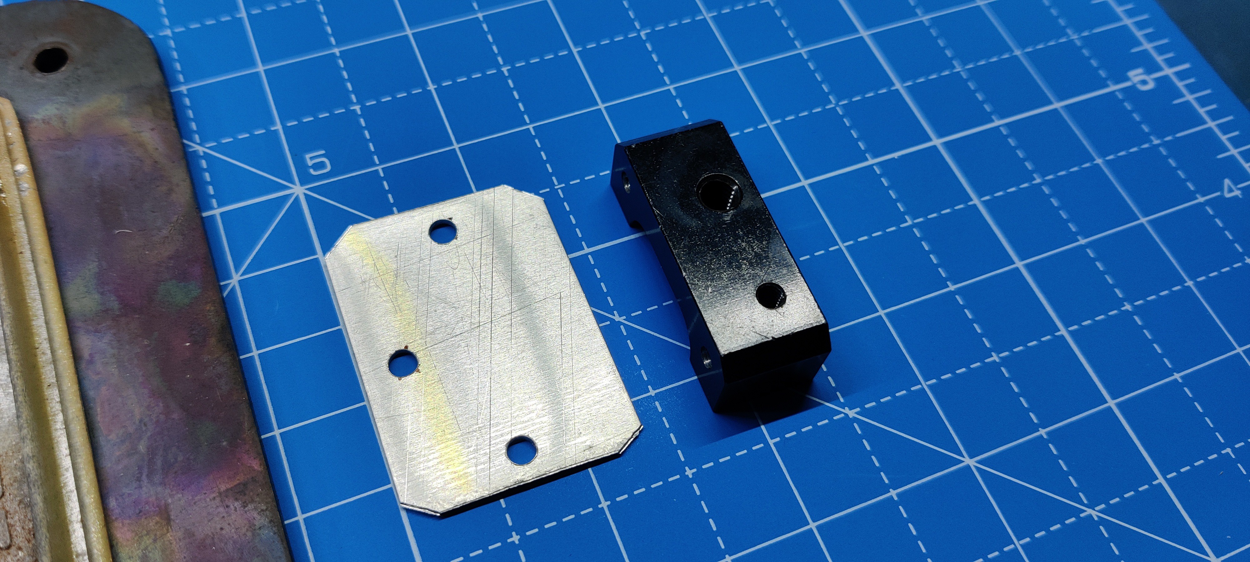
We create a mounting plate out of aluminum sheet that fits into the mounting holes on the existing thermostat. We then attach an aluminum block to the aluminum sheet to hold the thermocouple probe in place.
The thermistor probe can easily be tightened onto the aluminum block because the threads on this block are the same size, M6.
Makeshift Reflow Hotplate
A clothes iron based PCB Reflow Hotplate with Temp Control, MAX6675 is being used with XIAO MCU.

Discussions
Become a Hackaday.io Member
Create an account to leave a comment. Already have an account? Log In.