 Arnov Sharma
-
1DESIGN
![]()
![]()
![]()
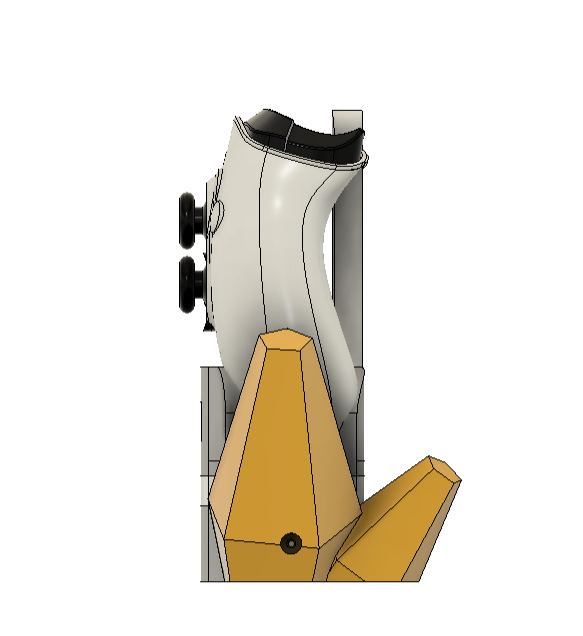
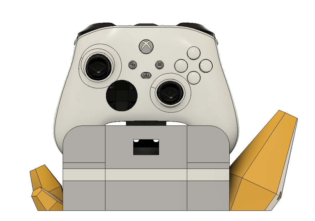
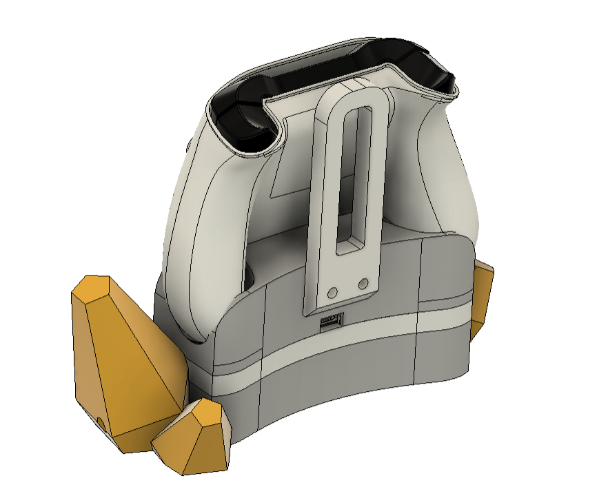
Our initial task was to design this project, which was made possible by a 3D model of the Xbox Controller.
The controller would be held up by its two handles on a base that would house an RGB driver PCB, according to my design.
In order to create the controller holder in the main holder body, we first chose the XBOX controller's face and selected the surface of the holder using the offset tool in the surface environment. Next, we create a holder body using the thicken command that is precisely the right size for supporting the controller from both handles.
We modeled the center section around the newly constructed holder body, and the result is a beautiful base that houses the circuit in the center, the battery at the bottom, and the Xbox Controller at the top.
The end product is a nice base that holds the Xbox Controller at the top, the battery at the bottom, and the circuit in the center. We designed the center section around the newly built holder body.
At last, we added a stand on the back side of the main holder body to add extra protection for keeping the XBOX Controller in its place.
After the model was complete, we exported the mesh files and used a 0.4mm nozzle with 20% infill to 3D print it in white and glass yellow PLA.
-
2CIRCUIT
![]()
![]()
![]()
The circuit that followed was made up primarily of 15 WS2812 RGB LEDs linked to an XIAO microcontroller. We have integrated the IP5306 IC Setup, a power management integrated circuit that is frequently used in power bank applications.
In these applications, we have one or more 3.7V lithium-ion cells that provide a stable 5V output with low- and high-cut capabilities as well as battery charging capabilities.
I have used this setup in many of of my previous projects, which you can checkout here:
https://www.hackster.io/Arnov_Sharma_makes/live-temp-meter-with-xiao-and-aht10-c482ea
https://www.hackster.io/Arnov_Sharma_makes/the-ultimate-camera-rig-with-portable-display-d4436d
https://www.hackster.io/Arnov_Sharma_makes/overengineered-pen-holder-2-0-5c0daf
-
3Seeed Fusion Service
![]()
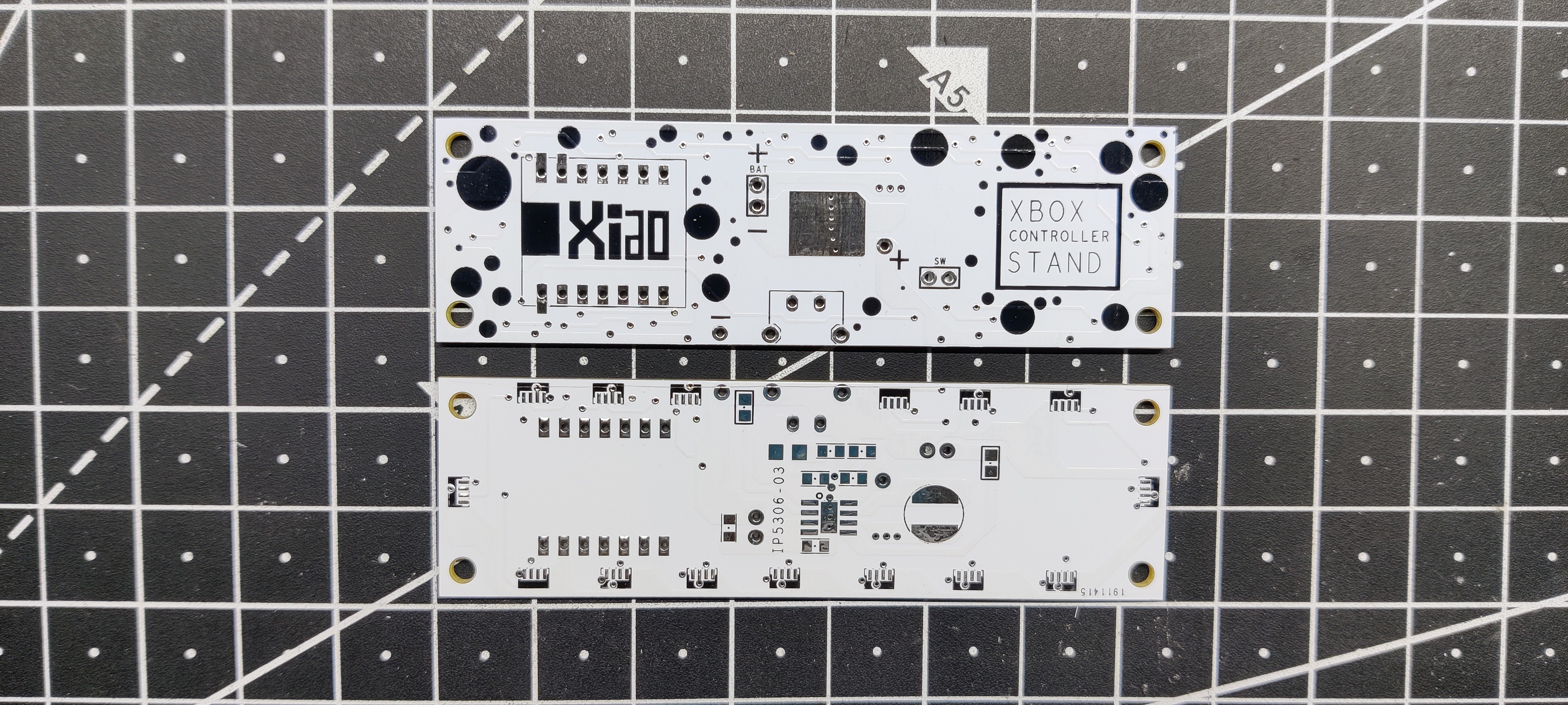
After finalizing the PCB and generating its Gerber data, I sent it to SEEED Studio for samples.
The PCB was ordered in a white solder mask with black silkscreen.
PCBs were received in a week, and their quality was super good considering the rate, which was also pretty low.
Seeed Fusion PCB Service offers one-stop prototyping for PCB manufacture and PCB assembly, and as a result, they produce superior-quality PCBs and fast turnkey PCBAs within 7 working days.
Seeed Studio Fusion PCB Assembly Service takes care of the entire fabrication process, from Seeed Studio Fusion Agile manufacturing and hardware customization to parts sourcing, assembly, and testing services, so you can be sure that they are getting a quality product.
After gauging market interest and verifying a working prototype, Seeed Propagate Service can help you bring the product to market with professional guidance and a strong network of connections.
Next is the PCB assembly process.
-
4PCB Assembly Process
![]()
![]()
![]()
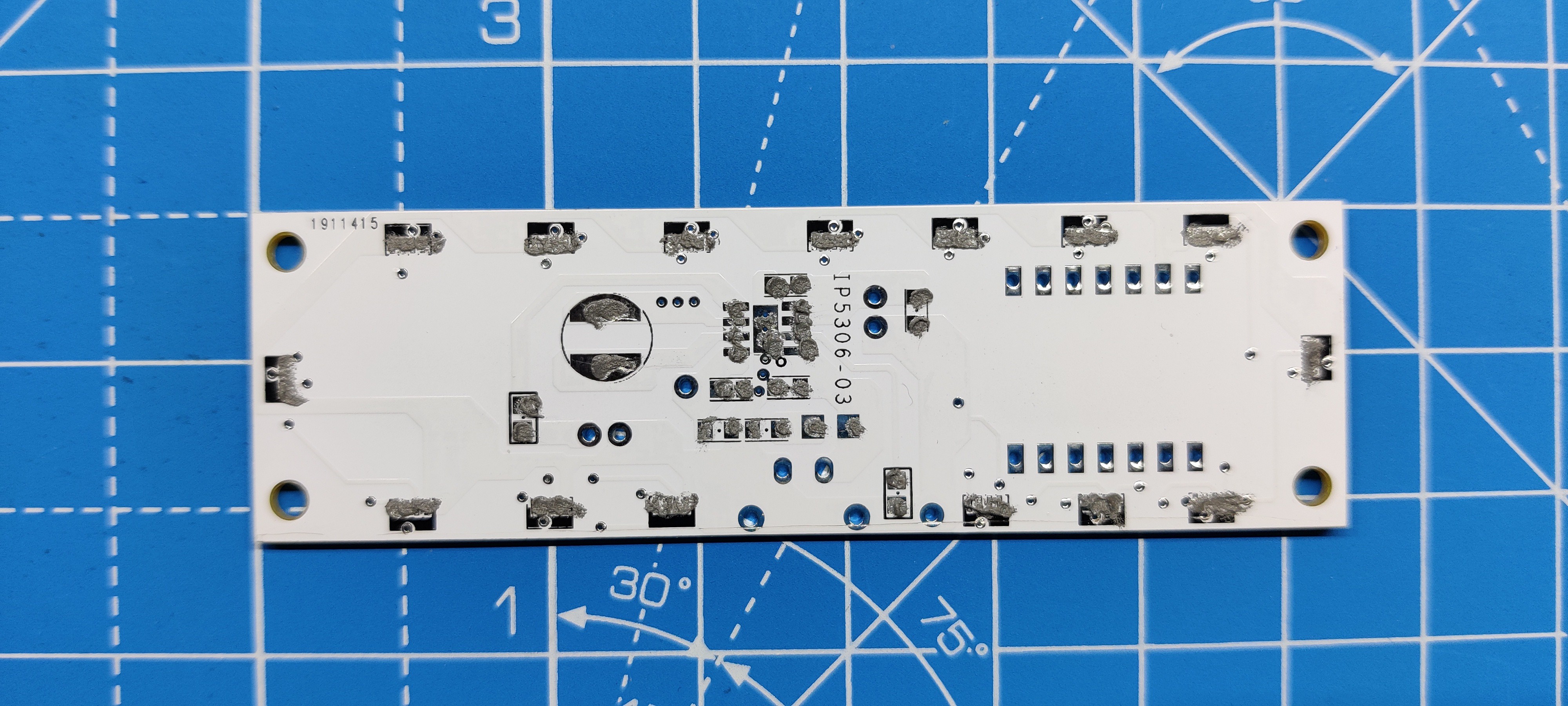
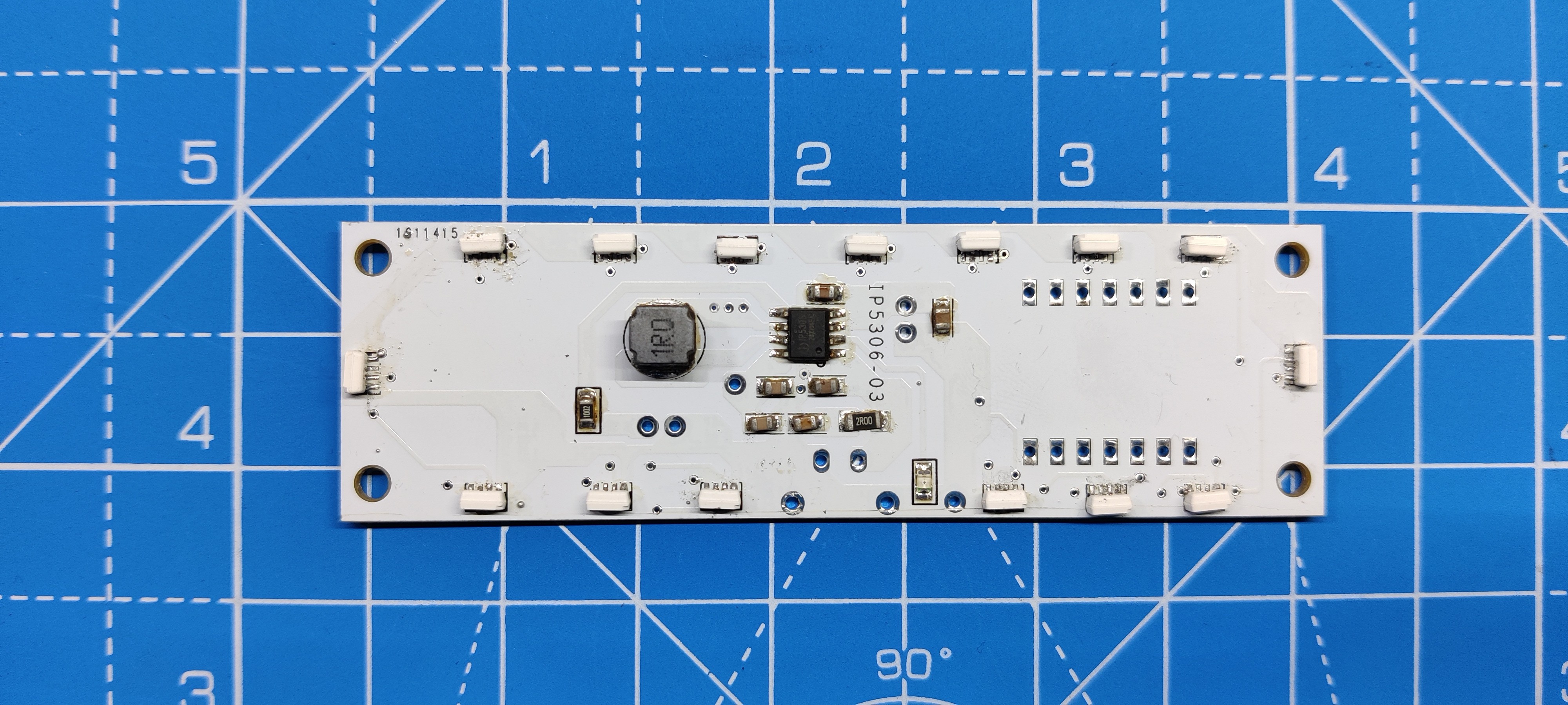
- Using a solder paste dispensing needle, we first add solder paste to each component pad individually to begin the PCB assembly process. In this instance, we are using standard 37/63 solder paste.
- Next, we pick and place all the SMD components in their places on the PCB using an ESD tweezer.
- With extreme caution, we lifted the complete circuit board and placed it on the SMT hotplate, which increases the PCB's temperature to the point at which the solder paste melts and all of the components are connected to their pads.
- Next, we add all the THT components, which include the header pin, JST CON, and USB Micro Port, to their locations and then solder their pads using a soldering iron.
-
5TESTING PROCESS
- Following PCB assembly, we connected the JST wire of the lithium cell to the JST connector on the circuit board and then connected the JST wire of the switch to the JST connector on the circuit board.
- To confirm if the power management system is functioning, we flip the switch and use a multimeter to measure the output voltage of the IP5306, which is 5V.
-
6CODE
#define FASTLED_ALLOW_INTERRUPTS 0
#include <FastLED.h>
FASTLED_USING_NAMESPACE

#define DATA_PIN            D0
#define NUM_LEDS            15
#define MAX_POWER_MILLIAMPS 500
#define LED_TYPE            WS2812B
#define COLOR_ORDER         GRB

//////////////////////////////////////////////////////////////////////////

CRGB leds[NUM_LEDS];

void setup() {
  delay( 3000); // 3 second delay for boot recovery, and a moment of silence
  FastLED.addLeds<LED_TYPE,DATA_PIN,COLOR_ORDER>(leds, NUM_LEDS)
        .setCorrection( TypicalLEDStrip );
  FastLED.setMaxPowerInVoltsAndMilliamps( 5, MAX_POWER_MILLIAMPS);
}

void loop()
{
  EVERY_N_MILLISECONDS( 20) {
    pacifica_loop();
    FastLED.show();
  }
}

CRGBPalette16 pacifica_palette_1 =
    { 0x000507, 0x000409, 0x00030B, 0x00030D, 0x000210, 0x000212, 0x000114, 0x000117,
      0x000019, 0x00001C, 0x000026, 0x000031, 0x00003B, 0x000046, 0x14554B, 0x28AA50 };
CRGBPalette16 pacifica_palette_2 =
    { 0x000507, 0x000409, 0x00030B, 0x00030D, 0x000210, 0x000212, 0x000114, 0x000117,
      0x000019, 0x00001C, 0x000026, 0x000031, 0x00003B, 0x000046, 0x0C5F52, 0x19BE5F };
CRGBPalette16 pacifica_palette_3 =
    { 0x000208, 0x00030E, 0x000514, 0x00061A, 0x000820, 0x000927, 0x000B2D, 0x000C33,
      0x000E39, 0x001040, 0x001450, 0x001860, 0x001C70, 0x002080, 0x1040BF, 0x2060FF };


void pacifica_loop()
{
  // Increment the four "color index start" counters, one for each wave layer.
  // Each is incremented at a different speed, and the speeds vary over time.
  static uint16_t sCIStart1, sCIStart2, sCIStart3, sCIStart4;
  static uint32_t sLastms = 0;
  uint32_t ms = GET_MILLIS();
  uint32_t deltams = ms - sLastms;
  sLastms = ms;
  uint16_t speedfactor1 = beatsin16(3, 179, 269);
  uint16_t speedfactor2 = beatsin16(4, 179, 269);
  uint32_t deltams1 = (deltams * speedfactor1) / 256;
  uint32_t deltams2 = (deltams * speedfactor2) / 256;
  uint32_t deltams21 = (deltams1 + deltams2) / 2;
  sCIStart1 += (deltams1 * beatsin88(1011,10,13));
  sCIStart2 -= (deltams21 * beatsin88(777,8,11));
  sCIStart3 -= (deltams1 * beatsin88(501,5,7));
  sCIStart4 -= (deltams2 * beatsin88(257,4,6));

  // Clear out the LED array to a dim background blue-green
  fill_solid( leds, NUM_LEDS, CRGB( 2, 6, 10));

  // Render each of four layers, with different scales and speeds, that vary over time
  pacifica_one_layer( pacifica_palette_1, sCIStart1, beatsin16( 3, 11 * 256, 14 * 256), beatsin8( 10, 70, 130), 0-beat16( 301) );
  pacifica_one_layer( pacifica_palette_2, sCIStart2, beatsin16( 4,  6 * 256,  9 * 256), beatsin8( 17, 40,  80), beat16( 401) );
  pacifica_one_layer( pacifica_palette_3, sCIStart3, 6 * 256, beatsin8( 9, 10,38), 0-beat16(503));
  pacifica_one_layer( pacifica_palette_3, sCIStart4, 5 * 256, beatsin8( 8, 10,28), beat16(601));

  // Add brighter 'whitecaps' where the waves lines up more
  pacifica_add_whitecaps();

  // Deepen the blues and greens a bit
  pacifica_deepen_colors();
}

// Add one layer of waves into the led array
void pacifica_one_layer( CRGBPalette16& p, uint16_t cistart, uint16_t wavescale, uint8_t bri, uint16_t ioff)
{
  uint16_t ci = cistart;
  uint16_t waveangle = ioff;
  uint16_t wavescale_half = (wavescale / 2) + 20;
  for( uint16_t i = 0; i < NUM_LEDS; i++) {
    waveangle += 250;
    uint16_t s16 = sin16( waveangle ) + 32768;
    uint16_t cs = scale16( s16 , wavescale_half ) + wavescale_half;
    ci += cs;
    uint16_t sindex16 = sin16( ci) + 32768;
    uint8_t sindex8 = scale16( sindex16, 240);
    CRGB c = ColorFromPalette( p, sindex8, bri, LINEARBLEND);
    leds[i] += c;
  }
}

// Add extra 'white' to areas where the four layers of light have lined up brightly
void pacifica_add_whitecaps()
{
  uint8_t basethreshold = beatsin8( 9, 55, 65);
  uint8_t wave = beat8( 7 );

  for( uint16_t i = 0; i < NUM_LEDS; i++) {
    uint8_t threshold = scale8( sin8( wave), 20) + basethreshold;
    wave += 7;
    uint8_t l = leds[i].getAverageLight();
    if( l > threshold) {
      uint8_t overage = l - threshold;
      uint8_t overage2 = qadd8( overage, overage);
      leds[i] += CRGB( overage, overage2, qadd8( overage2, overage2));
    }
  }
}

// Deepen the blues and greens
void pacifica_deepen_colors()
{
  for( uint16_t i = 0; i < NUM_LEDS; i++) {
    leds[i].blue = scale8( leds[i].blue,  145);
    leds[i].green= scale8( leds[i].green, 200);
    leds[i] |= CRGB( 2, 5, 7);
  }
}
Here's the sketch that we are using in this project, and its a simple one. This sketch is called Pacifica, and it generates gentle, blue-green ocean waves like light from WS2812B LEDs. This is an example sketch from the FastLED Library that you need to install first before using this sketch.
-
7Main Assembly
- First, we inserted two M3 screw inserts into the rear side of the main body to begin the major assembly procedure.
- Next, we used four M2 screws to attach the center portion of the main body to the upper part.
- After that, we positioned the switch on top of the main body from the front..
- Next, we reconnect the JST wire harness with the JST connector on the circuit and place the circuit into the middle section. We then secure the circuit in its place using four M2 screws.
- After that, we secured the assembly and added the battery JST connector to the circuit.
- The model was designed so that, in order to keep everything in the correct position, we would only need one screw from each side to hold the top, bottom, middle portion, and geode together.
- We tighten the M2 screw from both the left and right sides of the middle body.
- Finally, we use two M3 bolts to attach the back support section to the back of the middle body.
The assembly is now complete.
-
8RESULT
After the tedious build, here's the result so far.
The best thing is that we used the same surface offset as the controller's handle, so it fits precisely in the holder and keeps the controller from falling out of place. This gives the Xbox controller stand an entirely unique appearance.
All we need to do is press the button on the front to turn on the RGB lights.
A few things still need to be worked on in the upcoming version: the circle requires more LEDs because they are producing fewer lumens, and we should reprint the central section of the light source using transparent PLA in Version 2.
Leave a comment if you need any help regarding this project. This is it for today, folks.
Thanks to Seeed Studio for supporting this project.
You guys can check them out if you need great PCB and stencil service for less cost and great quality.
And I'll be back with a new project pretty soon!
Over Engineered XBOX Controller Stand
Made a OverEngineered XBOX Controller Stand with RGB LEDs inbuild, setup is powered by a Custom XIAO MCU based Circuit.


Discussions
Become a Hackaday.io Member
Create an account to leave a comment. Already have an account? Log In.