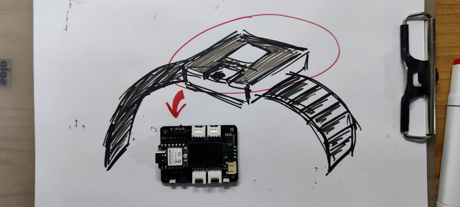
An XIAO ESP32C3 microcontroller and an XIAO extension board manufactured by Seeed Studio comprised the heart of this project.
It comes with rich peripherals that include an OLED, RTC, SD Card Sot, passive buzzer, reset/user button, 5V servo connector, and Grove connector for pairing multiple Grove devices with XIAO.
We can power the entire setup using any Li-ion or LiPo cell thanks to its integrated Li-ion charging circuit.
If you would like to get one for yourself, here is the link to its page.
Visit Seeed Studio to get a wide range of services, including 3D printing, PCB/PCBA, and microcontroller/module services.
2
Design
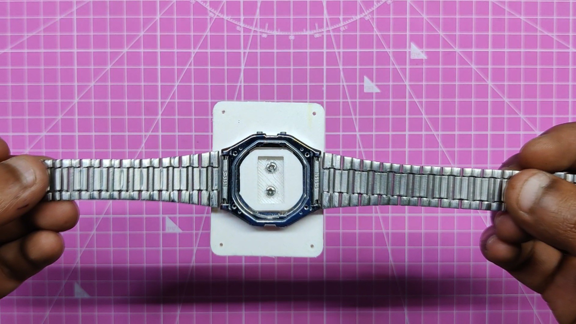
Initially, we had the idea of reviving an outdated CASIO vintage watch frame that I had with the XIAO expansion board.
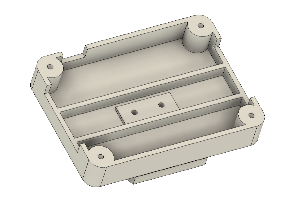
The expansion board contains the display, microcontroller, RTC and even the battery, so we prepared a rectangular holder that will be fixed to the existing watch frame and will house the expansion board and battery.
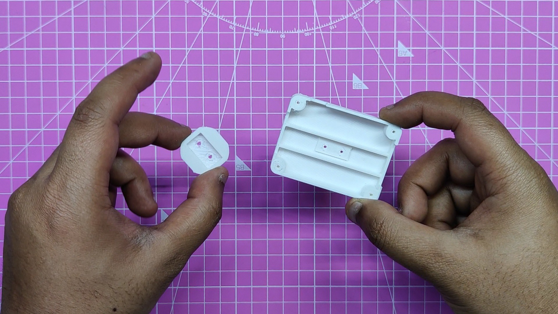
Two sections of the expansion board holder were modeled. The battery was positioned between the expansion board and the top body, and the top portion essentially served as a holder that the expansion board was screwed onto.
On the bottom side, there's another part that is added from the internal side of the watch frame; this part is screwed on the bottom side of the top part through two M2 screws and holds the watch frame.
After finalizing the model, we 3D printed both parts with white PLA through a 0.4-mm nozzle and 20% infill.
3
Assembly Process
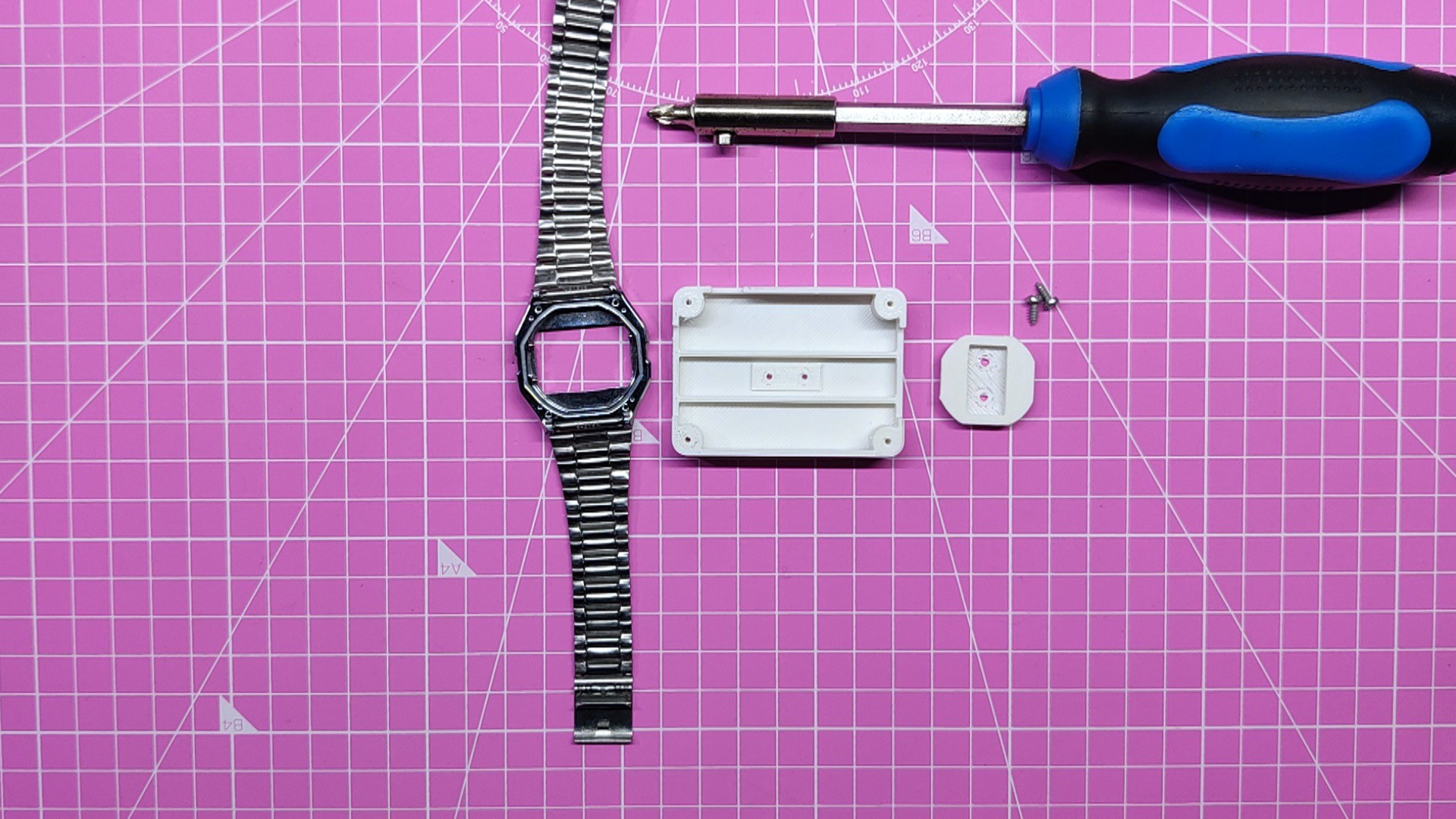
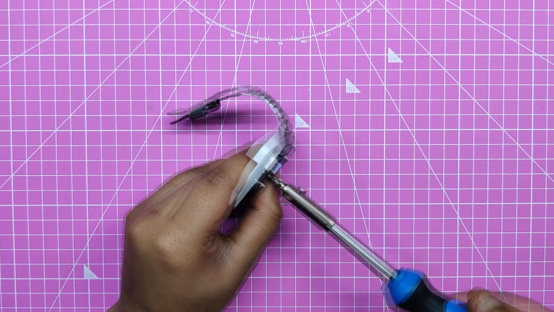
The holder part is added from the bottom side of the frame after the top part has been assembled onto the watch frame. Two M2 screws are used to secure everything in place
4
Assembly Process: Final
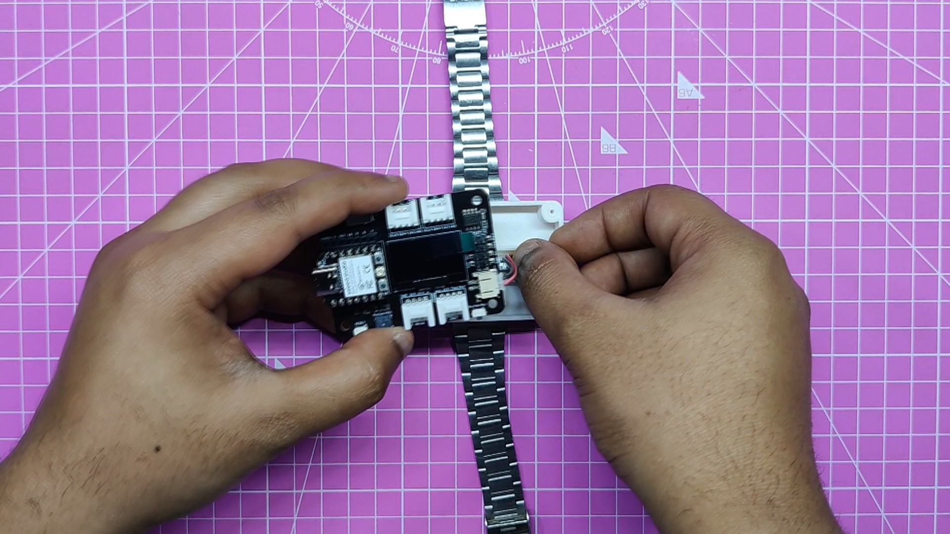
Next, we connected the JST connector of the expansion board to the JST connector of the LiPo cell.
Next, we insert the battery into the top part and secure the expansion board in its proper position.
Next, by using four m2 screws, we secure the expansion board on the top part.
Assembly is now complete; all that is left to do is add code to the XIAO Board and test-run the project.
This sketch essentially creates a real-time clock using the PCF8563 RTC and displays the date and time on a 128x64 OLED display
6
RESULT
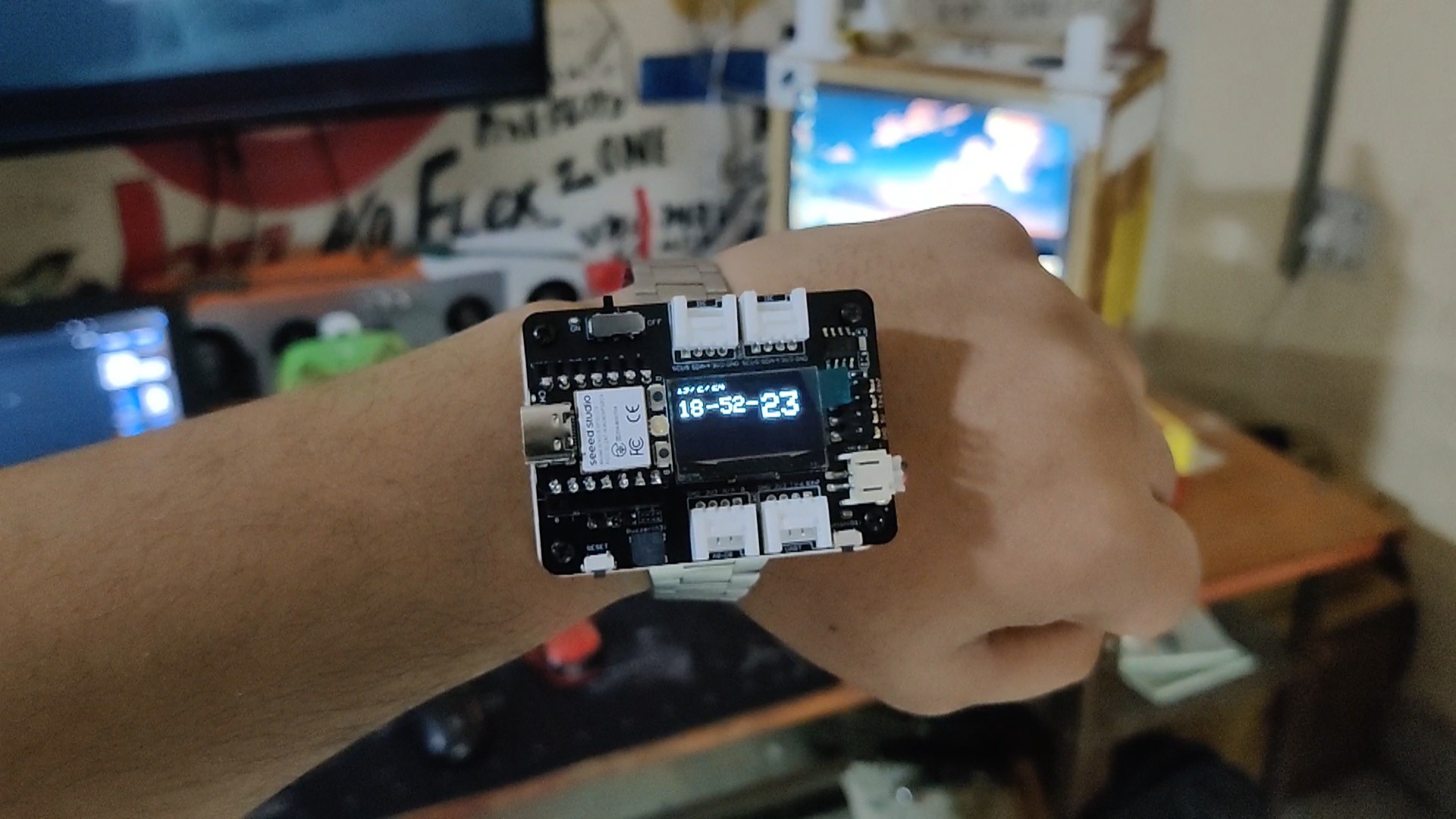
Here's the end result of this super-small build: a digital wrist watch.
The XIAO expansion board serves as a functional clock module in this useful and functional watch. The inbuilt buzzer can be used as an alarm indicator should we introduce an alarm feature to this watch in the future.
We also needed to install a CR1220 lithium cell on the cell hold provided on the bottom side of the expansion board in order to use the RTC.
Leave a comment if you need any help regarding this project. This is it for today, folks.
 Arnov Sharma


Discussions
Become a Hackaday.io Member
Create an account to leave a comment. Already have an account? Log In.