tomcircuit
-
Flashback : Measurements
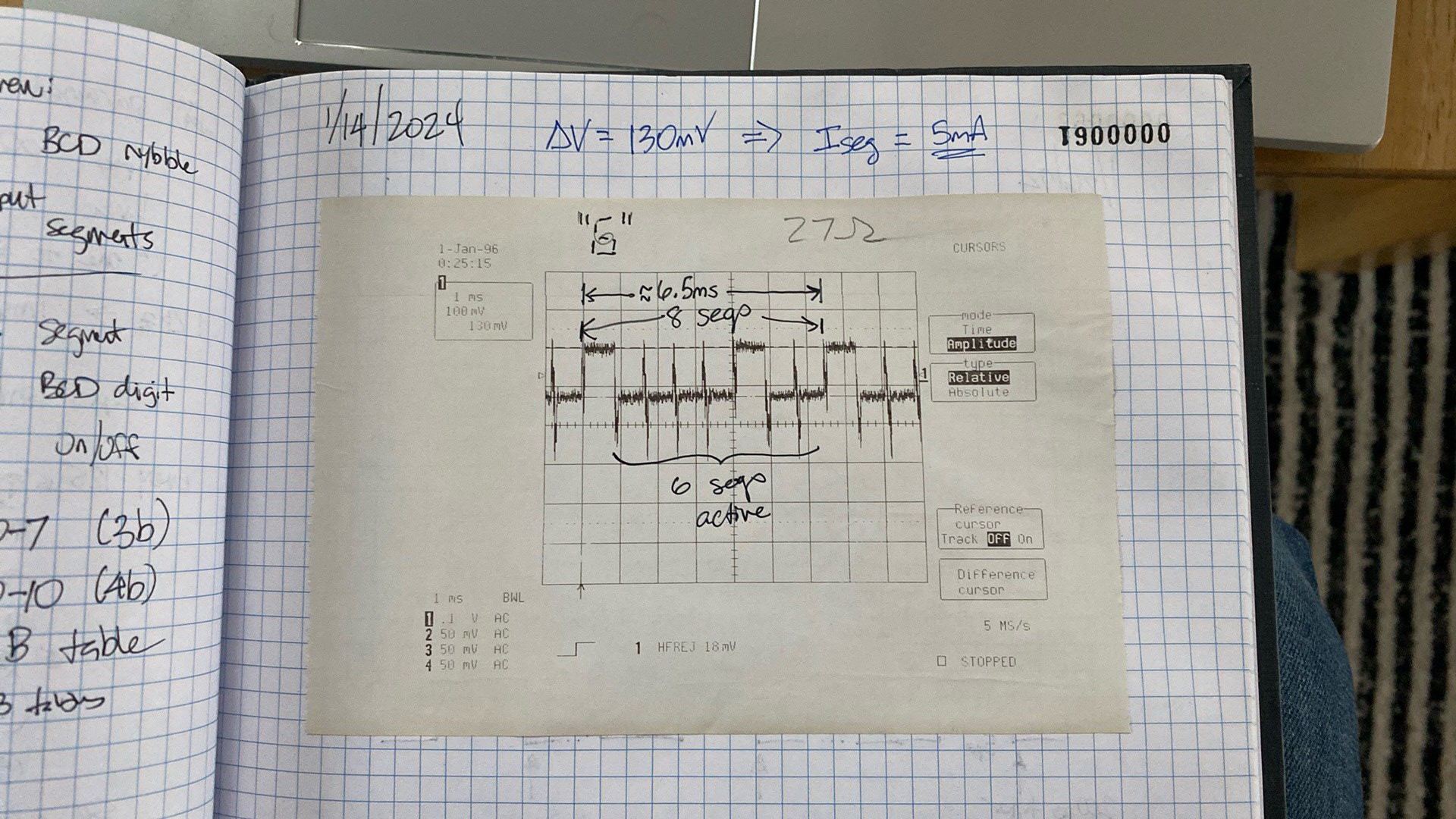
02/28/2024 at 22:11 • 4 commentsI carefully opened a TI-55 donor unit and inserted a 27ohm resistor in series with one of the digit cathodes. I captured the display sequence on my trusty LeCroy oscilloscope and dumped to the built-in thermal printer - TI-55 LED timing and Vfwd measurement
![]()
There are several important observations that can be made from this plot:
- The LED is scanned by segment rather than by digit. That is, all of the "a" segment anodes are sourced, but only the digit common cathodes in the digit positions that have this segment illuminated are sunk. This means that the TMC1500 has only to 'scan' 8 segments (a-g, dp) rather than the more intuitive approach of scanning 12 digits. This is covered in TI patent Number 4,014,012 so was not a surprise to me.
- During a display cycle, each segment anode is energized for 800us, and the overall display cycle duration is 6.4ms. TI patent Number 4,125,901 describes how, during a display cycle, the CPU cycle interval is increased by a factor of 32, so that the LED display is visible. This implies that the normal CPU cycle interval is 6.4ms / 32 = 200us.
- The voltage across the 27 ohm series resistor I fitted to one digit's common cathode, when energized, is 130mV. Therefore, the segment current is 5mA. If all 12 digits have the same segment active, the segment driver must source 5mA * 12 = 60mA. This is a bit much for a single MCU GPIO output pin, so PNP BJT or P-MOS will be required for each segment line. On the other hand, each digit has only one segment active at any one time, so the most current the digit drivers must sink is 5mA.
Thank you, TI-55. That didn't hurt a bit now, did it?
-
Flashback : Prework
02/28/2024 at 22:07 • 0 commentsThe more I read about the TI-57, the more I wanted to fix mine. Of course, these are easily found on a-large-well-known-online-auction-site for modest prices - typically $40 or less. Like most hobby projects, my goals were entirely devoid of practicality. Vive les fous!
The heart of the TI-57 is a calculator-on-a-chip executed in 4-phase PMOS. If you've not yet gone down this rabbithole, I strongly recommend a read through Ken Shirriff's excellent coverage of this subject. So, this means multiple supply rails and oddball voltages (at least, oddball in this day and age) are required. The IC designers at TI built the substrate bias voltage generator into the TMC1500 family, vastly simplifying things by allowing operation from a single -9V rail. Of course, we can call -9V "ground" and that makes the TI-57 ground "+9V". It's why when you power one of these calculators from a 9V battery, you need to connect the battery's POSITIVE terminal to the BLACK wire, and NEAGATIVE terminal to the RED wire. Um...thanks, TI.
Much of how the TMC1500 works can be learned from studying the incredibly detailed and completely helpful US Patents that TI applied for prior to the production of the TI-57. Jeff Parsons has collected the most important ones here, and it is well worth studying them - if not only as standout examples of well-written patents! Because my goal was to replace the TMC1500 IC with a microcontroller and some discrete components, I had some questions about the "rest" of the calculator - mostly the 12-digit LED display. Digging around online in 1970's eta TI optoelectronic databooks was marginally helpful, but nothing beats an actual measurement of the LED in action to gather some critical items:
- LED segment ON time
- LED segment forward current
- LED segment voltage drop
The TI-57 has a lot in common with a cheaper model, the TI-55. It's the same TMC1500 family process, with a different keyboard layout and ROM content. These are even cheaper to obtain, so I picked a couple up for experimental purposes.
TI-57 Programmable Calculator Hardware Retrofit
A modern MCU-based hardware replacement for the venerable TMC1501 used in the Texas Instruments TI-57 LED calculator.