Close
0%
0%

DIY Golf Launch Monitor

Launch monitor using low-cost raspberry pi and camera hardware to determine ball launch speed, angles and spin

Similar projects worth following
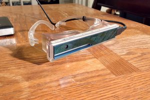
The DIY LM project has produced software and hardware designs for a fully-functional golf launch monitor that avoids the need for expensive high shutter-speed and high frame-rate cameras. We've developed techniques for high-speed, infrared, strobe-based image capture and processing using cameras such as the Pi Global Shutter camera (~$50 retail) and Raspberry Pi single board computers. A first version is built and currently under test.

See the Project Log pages for the latest news, especially the comparison of the DIY LM against a commercial LM!

The LM now accurately determines ball speed, launch angles, and--importantly--ball spin in 3 axes. The output of the system is accessible on a stand-alone web-based app. Outputs and interfaces to popular golf-course simulators including GsPro and E6 are working.

The project will likely be released as open-source, though patent applications on the IP have been filed to keep options open.

Overview

My personal goal has been to use this project as a learning platform.  So far, I’ve been able to explore all sorts of software and hardware that I hadn’t worked with previously.  I’ve been  getting to learn all sorts of new technology, techniques, libraries, and platforms.  This has also forced me to spin up on my linear algebra again.  

Technologies

Some of the technologies in use so far are:

The software is written almost entirely in C++, with the goal of having the codebase look close to commercial standards in terms of testability, architecture, and documentation.  There are some utilities (for functions like camera and lens calibration) that were easier to implement in Python and/or Unix scripts. 

Cost

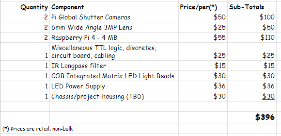
We’d like to have the entire system cost less than US$300. We're currently over-budget by about a hundred dollars, but have plans that should bring that price down.  For example, the new Raspberry Pi 5 should be able to support both of the system cameras, which could decrease the price by around $50 by avoiding a second Pi.

The high-level parts list at this time:
Additional Project Videos:
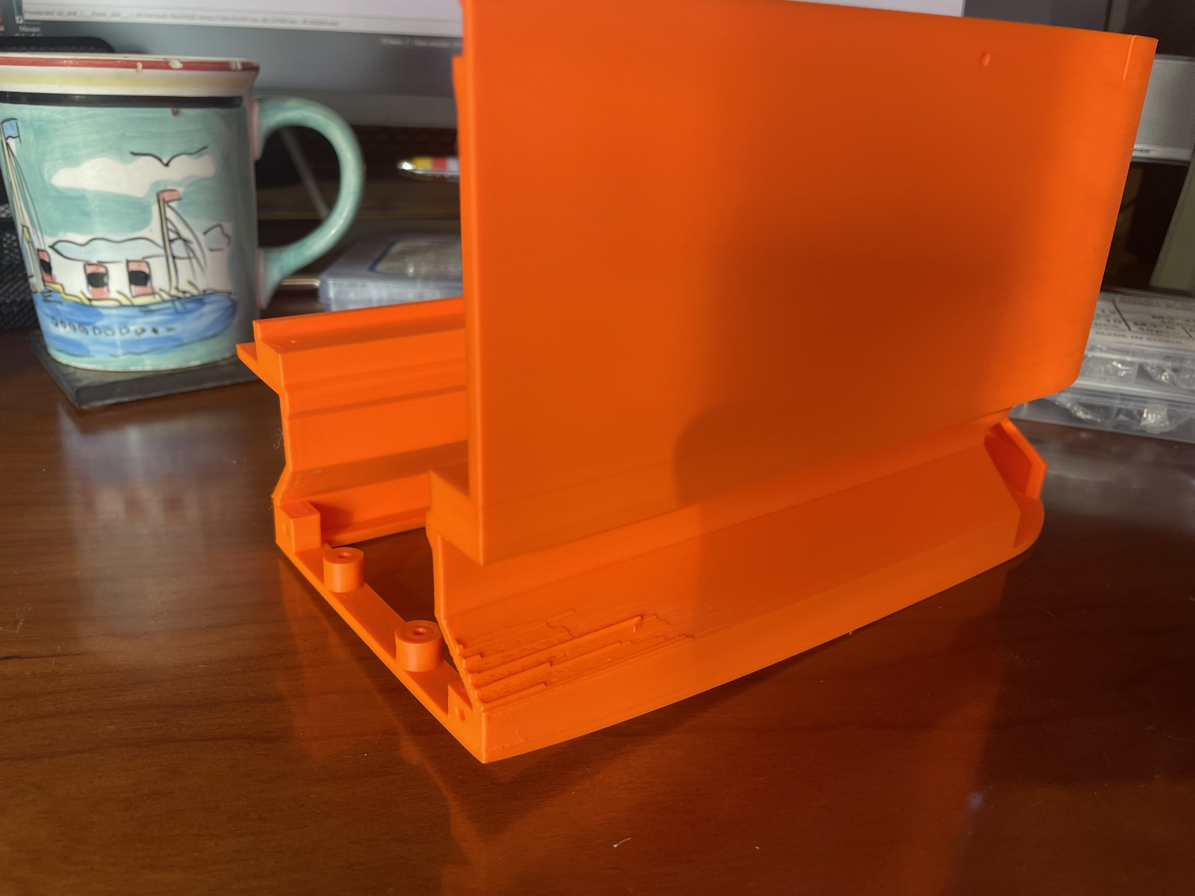
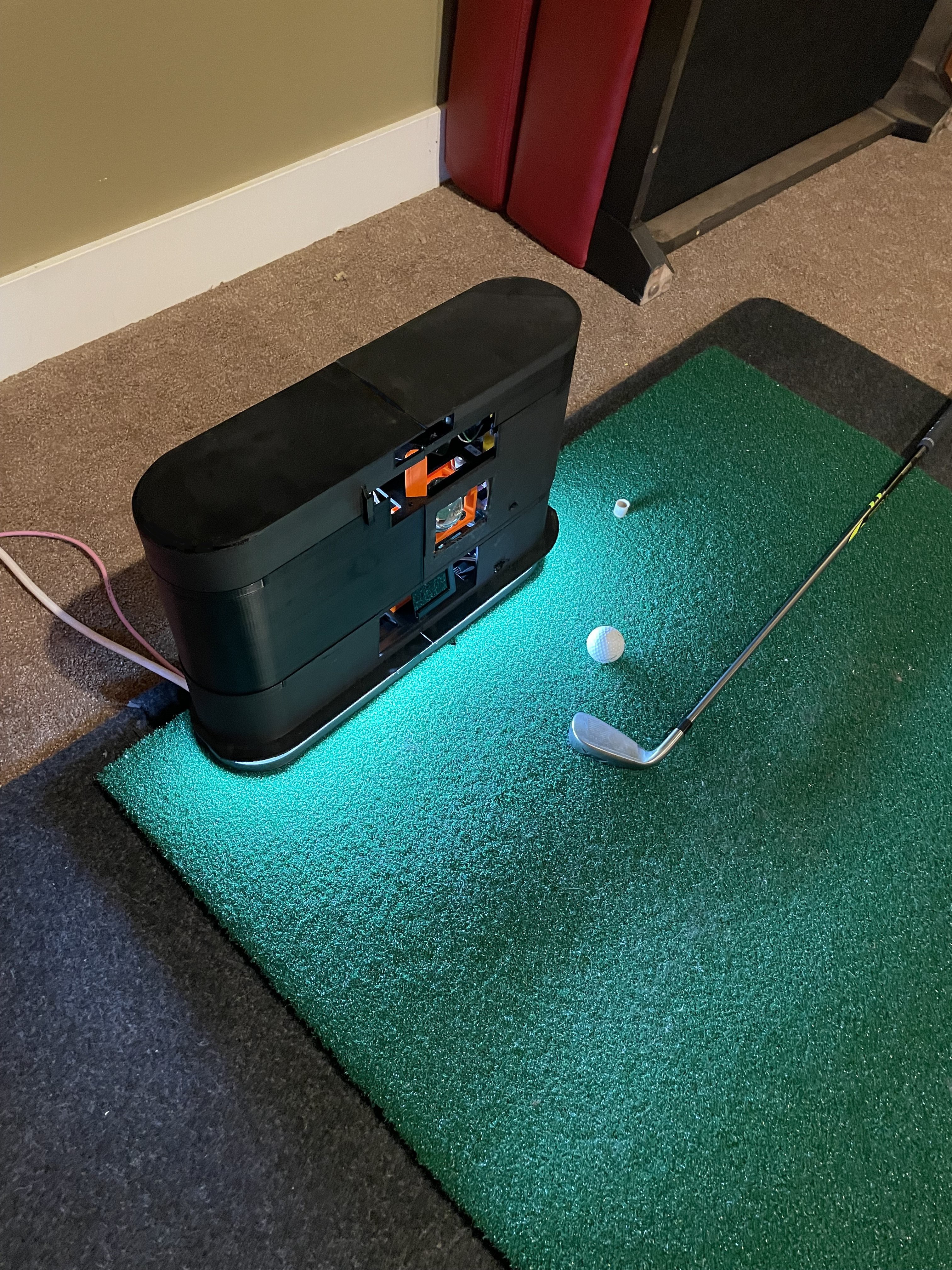
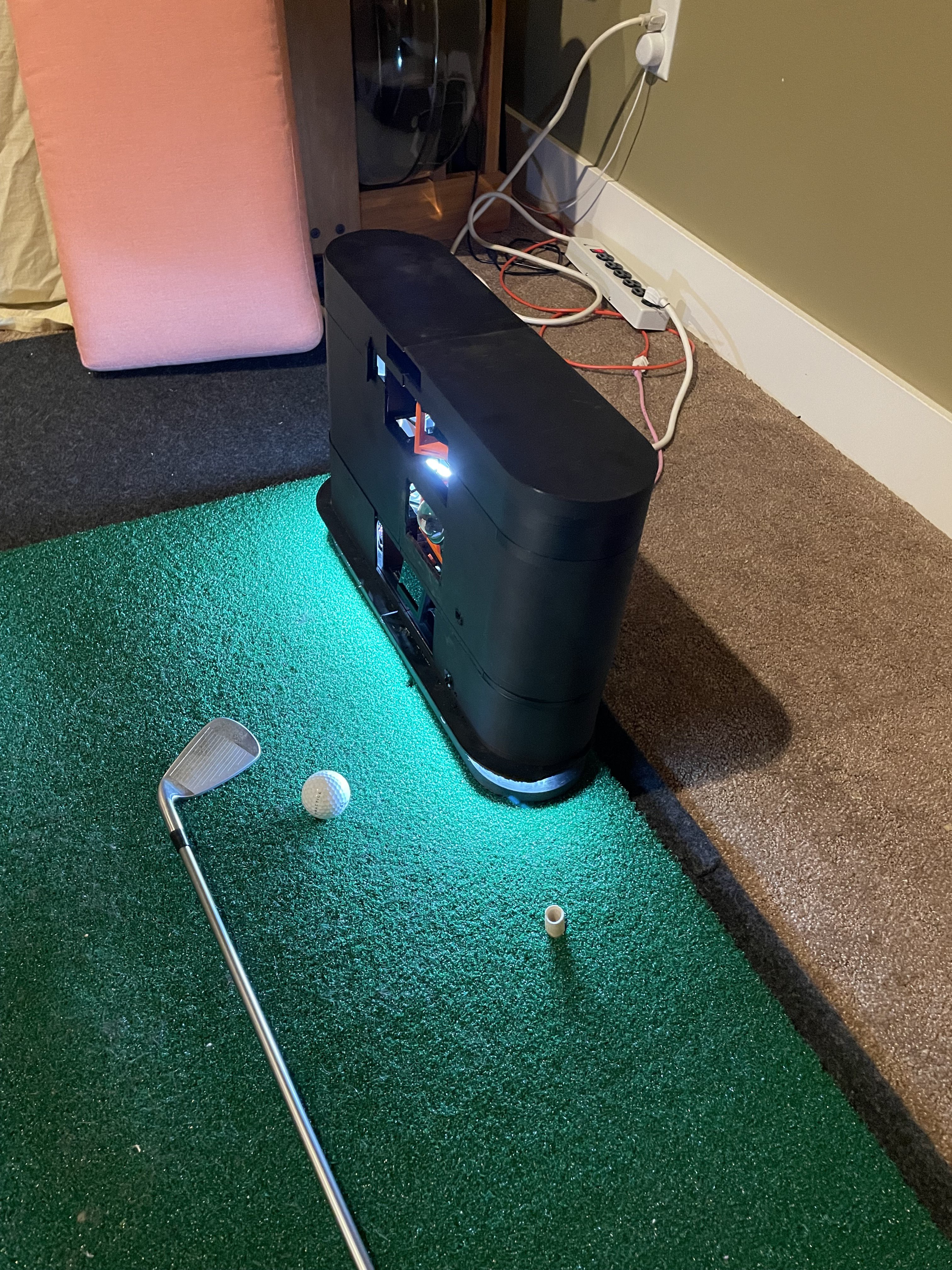
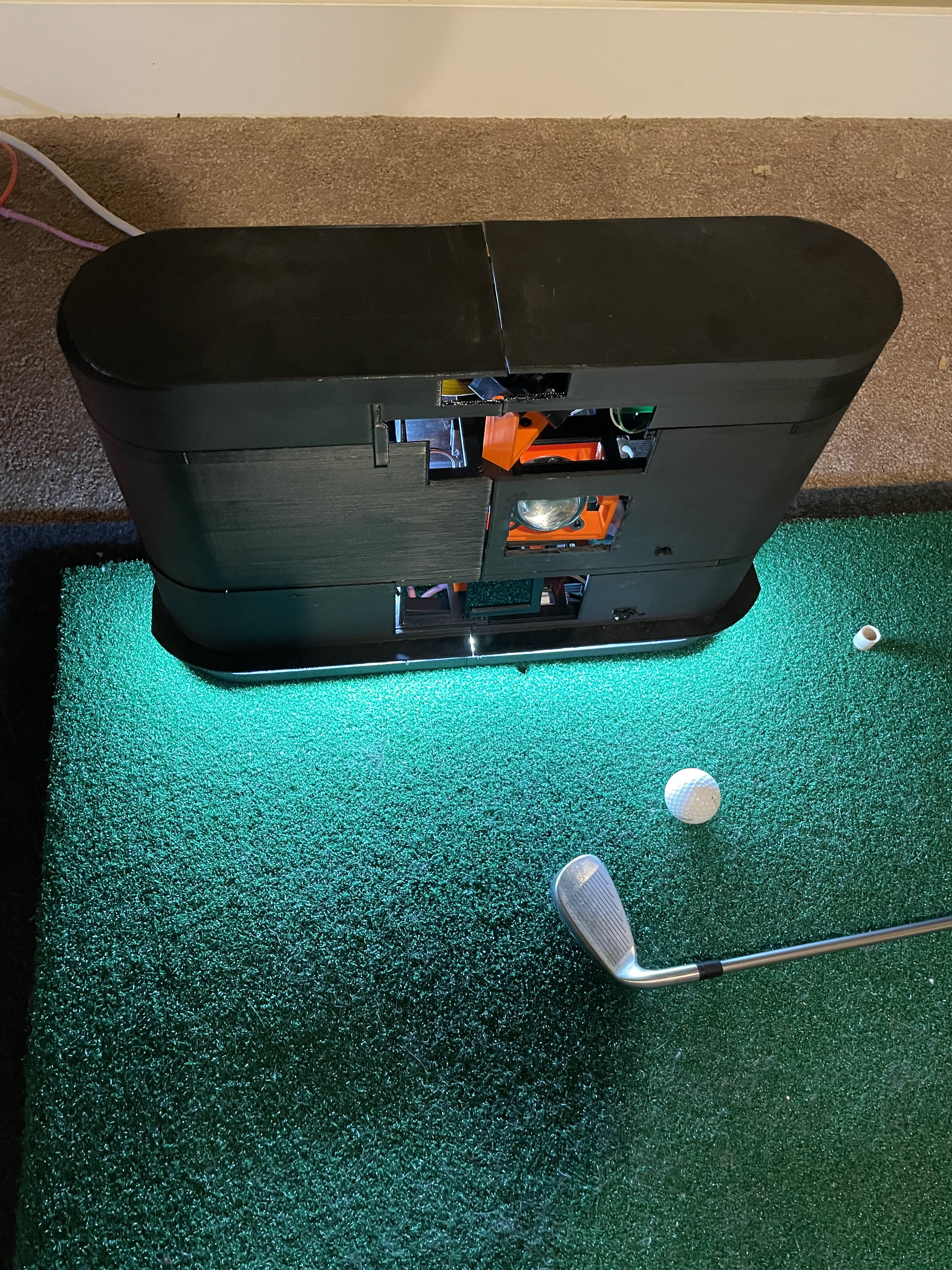
First DIY LM Enclosure 2.jpg

Prototype LM Enclosure

JPEG Image - 4.34 MB - 10/01/2024 at 19:48

Preview

  • Worst ASMR Video Ever

    James Pilgrim6 days ago 1 comment

    This is the first (and hopefully last ever) ASMR video from the DIY Launch Monitor Project:

    Back story is that the sound of pulling 3D printed parts off the print bed, as well as pulling off the printed supports, is surprisingly cool.  And apparently kinda popular on youTube.  See, e.g., here and here.

    So, why not make a goofy video of our own to exhibit those sounds? Turns out, there are lots of reasons.  Like because, we're software and hardware developers, not videographers.  And also the fact that recording the sounds with any fidelity is harder than it might seem.  Especially using rudimentary recording equipment.

    Fortunately, an ancient Blue USB microphone was located, and that helped a lot. :)

    _________________________

    On a serious note, we've been doing some work to try to ensure that folks who eventually build their own version of the DIY LM will be successful doing so.  One of the more difficult parts of the build so far has  been the varied, inconsistent success we've had with printing the enclosure parts.  It's harder than it looks to get consistent results, and we want to ensure that it goes as easily as possible.  

    To that end, we've been printing on different printers and with different types and brands of plastic filament to see what works best.  That's where the ASMR video came from.  Hopefully some re-designs that are in progress will make this easier for folks.  

    Some other areas of concern are the calibration process (which could use some more support tools) and just the process of getting a couple of Raspberry Pi's set up as a development and runtime environment for the rest of the software.  Hacking the Pi Global Shutter camera to support external shutter triggering isn't easy either, especially if you don't have the steady hands of a surgeon. :/  An upcoming log post will go into some of the things we're learning about getting an open source project ready to release into the wild.

    Anyway, we're continuing to knock off some of the rough edges of the system so that others will hopefully one day be able to replicate it on their own.  On that note, we'll soo be looking for a couple of volunteers to try out an alpha version of the system design to see how hard it will be to replicate.  More on that later...

  • Pre-Release Considerations - Safety First!

    James Pilgrim10/28/2024 at 18:46 1 comment

    The two schematics below show the initial version of the connector board (on the top/left) and the new version (on the bottom/right).  They both do the same basic thing -- opto-isolation and high voltage switching for the strobe board and the camera trigger signals.

    So, why the change?

    Well, now that we’re starting to think about what needs to be done before releasing the project into the wild, there are a lot of considerations.  They include things like proper attribution of open-source, IP management, ease of building and testing, and … safety!

    One issue that came up in the safety review was the fact that the original connection board design would allow the LED strobe board to be full ‘on’ continually if the power from the Raspberry Pi failed, or if the Pi otherwise became disconnected from the board.  The problem was that if a 100 watt, densely-packed LED array is on for any more than a few seconds, it starts to get really hot.  Like, hot enough to potentially even melt its #d printed plastic mounting hardware!

    This was a good (if painful) lesson in identifying and considering failure modes earlier in the design process, where things are easier to accommodate and/or protect against.  The circuit in the connector board is pretty simple, requiring an non-inverting opto-isolator among other things.  One easy way to do so (other than switching from a pull-up to a pull-down transistor on certain opto-isolation ICs), was just to add an inverter to the input signal.  That’s the red-colored path in the top/left schematic.  

    But, we hadn’t thought of the consequences of inverting the input, as opposed to adding the inverter after the isolator as in the purple path in the bottom/right schematic.  The right-most circuit has no other material downsides, but it also has the benefit that the strobe output to the 12 V MOSFET switch will go to low in the event of most failure modes, like a loss of power from the Sys1_Conn from the first Raspberry Pi or anything else that would cause power to the 7404 hex inverter chip to fail.  The opposite is true of the original circuit, where a failure causes the input to the isolator to go low, which causes the output to go high and switch on the strobe.  So, the new circuit inverts the output, not the input.  This should vastly decrease the chances of the LED array ever being on for more than a few microseconds at a time.

    Easy fix, but required another run of PCB boards. :/  More great lessons from this project…

  • Design For Manufacture, They Told Us...

    James Pilgrim10/03/2024 at 15:21 0 comments

    Apparently the best way to learn what designs DO NOT work reliably is just to make every 3D printing mistake in the book as we go. Which we are doing quite well.  For example, the image below shows the result of printing the enclosure design with a different filament type (PLA in this case) to see how it would work.  The result indicates insufficient print-bed adhesion as well as (possibly) over-aggressive cooling tuning resulting in pull-away and part warping.  New design will have a more filled-in base layer.

    Things always look wonderful in the CAD software, but then you hit print and ... <doh> ...

  • First Looks at DIY Launch Monitor Enclosure

    James Pilgrim09/30/2024 at 17:25 0 comments

    The work on the enclosure is starting to pay off.  After some investments in equipment, CAD software and the (sometimes painful) learning curves, we've got the DIY LM in its first, prototype enclosure.  A less hacked-together version is being built presently.  

    Anyway, here's a few pictures of the first stab at it...

  • It Works !

    James Pilgrim07/15/2024 at 21:47 1 comment

    Finally returned from a work hiatus and got back into our Uneekor-based test environment.  That environment is set up to make comparisons between the DIY LM and a Uneekor LM.  This post details an example comparison using some new logging facilities that were designed for just this purpose.  

    For the impatient, the short summary for the first sample is:

    Now onto the details.  First, it’s been difficult to get the two strobe based LM systems not to interfere with each other, but with the help of some more image processing, we can frequently get some decent comparisons now.  More details on the comparison methodology later.  We’re lucky to have a Uneekor as a measuring stick for the DIY LM, but it does come with its challenges.  Primarily, it’s a measuring stick that–when used–often changes the length of the thing being measured! :/  That said, it does work well enough with the DIY LM to use it to confirm the basic workings of the LM and to hopefully provide a wide worst-case accuracy analysis.

    For this first example, here’s a 7-iron shot (summary above), starting with teed-up ball and its position identification:

    This first shot is not strobed, so doesn’t have the same problems as imaging the ball in flight.  

    The in-flight images are shown below, with the identifications of the ball positions in the second image.

    You can see that the circle identification for Ball 4 is definitely off, and even Ball 3 isn’t perfect.  This seems to happen most of the time when the Uneekor’s strobes are blinking at the same time as the DIY LM.  Fortunately, when the DIY LM is running in its usual way (by itself), the circle identification is usually spot-on.  For example, here’s a typical identification when the Uneekor isn’t interfering:

    Moving on to spin calculation, in our present example the 3D ball rotation rates are calculated using the following images of the balls.  The first two images are the images used to determine an angular displacement between the balls from one point in time to another a couple of milliseconds later.  The third image is a visual sanity-check.  It shows the result of the first image rotated in 3D using the estimated angles that are used to calculate the DIY LM’s spin values.  As shown, it looks fairly close, but maybe just a little under-rotated in terms of back spin.

    The spin calculation is even better, of course, when the circle identification is closer to perfect when the Uneekor isn’t in use.  That completes the review of the artifacts the system stores for each shot.

    Ultimately, the question is what the real-world (well, real-world simulator) results are.  In other words, how do the differences listed below for the DIY LM data actually affect where the (simulated) ball ends up? 

    To recap, those numeric element-by-element errors are on the last line of the spreadsheet below:  

    It is fairly easy to determine how the above differences affect where the simulator projects the ball will land on the virtual golf course.  To do so, we injected the original Uneekor-based shot into an E6 simulator, and then followed that by injecting the same shot, but modified by using the DIY LM values instead of the Uneekor values.  Just one value (HLA, speed, etc.) is changed at a time except for the last injected ball.  The JSON-driven data is:

    "kInterShotInjectionPauseSeconds": 20,
                "test_shots_to_inject": {
                    "1": {            ⇐=================== This is the Uneekor result with all of its data
                        "Speed": 71.9,
                        "BackSpin": 4153,
                        "SideSpin": -871,
                        "HLA": -2.0,
                        "VLA": 21.1
                    },
                    "2": {            ⇐=================== This one is mostly the Uneekor data, but with the ball speed from the DIY LM
                        "Speed": 73.4,
                        "BackSpin": 4153,
                        "SideSpin": -871,
                        "HLA": -2.0,
                        "VLA": 21.1
                    },
                    "3": {
                        "Speed": 71.9,
                        "BackSpin": 3968,
                        "SideSpin": -871,
                        "HLA": -2.0,
                        "VLA": 21.1
                    },
                    "4": {
    ...
    Read more »

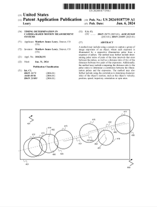
  • First Patent Application Published

    James Pilgrim06/06/2024 at 17:49 0 comments

    Our first U.S. patent application was published by the USPTO today.  

  • A Little Faster - Fastest Recorded Ball on DIY LM So Far...

    James Pilgrim06/06/2024 at 17:44 0 comments

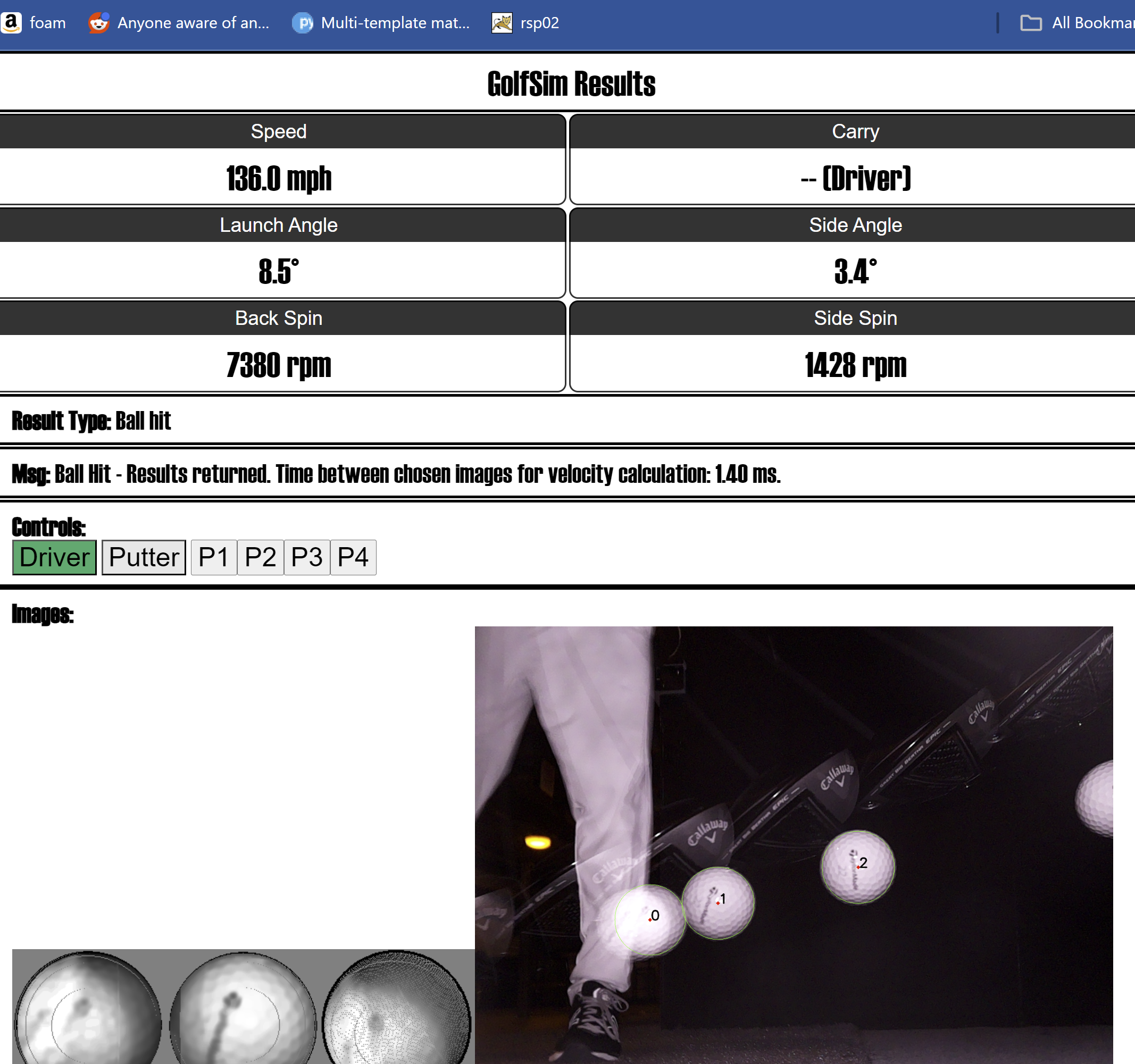
    Here's the fastest recorded shot processed by the DIY LM so far.  136mph (61 m/s).  Still hoping to get something a lot closer to 100m/s.  I think it's the fastest back-spin so far as well.  Thanks to Dave L. for the help!

  • First > 100 mph Shot

    James Pilgrim05/23/2024 at 21:16 0 comments

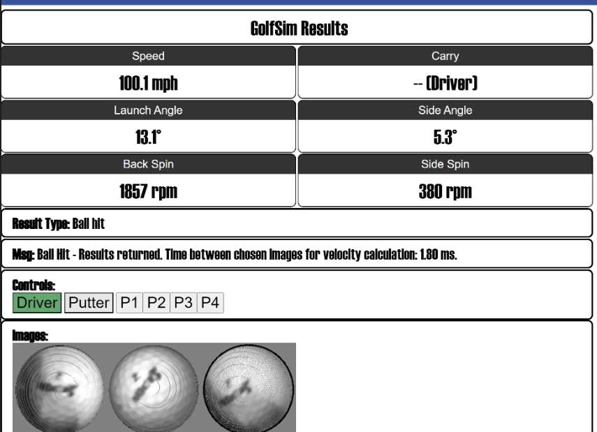
    Ok, so that's not very fast, but when testing something today, I took a club and just tried to really wack the ball.  And I noticed that for the first time that I can remember, the system recorded a shot (barely!) over 100 mph (45 m/s).  Sadly, I can't hit the ball a whole lot faster than that, but it appeared to be recorded correctly.  There was also plenty of additional room on the screen for the strobe pulses to be pushed further apart and further to the right of the screen.  That means that higher speeds should not be a problem.

    Unfortunately, I had the "on" strobe set to an unusually long time (>30uS), so that may have contributed to the blurring that is visible in the ball-spin analysis images.  Which in turn resulted in an inaccurate spin measurement as seen in the mis-match between the second ball image and the as-calculated-spin ball (third ball image).  Still, kind of satisfying.

  • Faster Shot Processing

    James Pilgrim05/22/2024 at 17:23 0 comments

    The LM is currently down to about 5 seconds delay between hitting the ball and seeing the shot in the golf simulator.  This includes full processing, including 3D spin down to 1 degree in each axis.  See video here.

    This speed is not as fast as it needs to be, but is getting closer.  The recent speed up is due primarily to utilizing more processing cores, turning down debugging, and moving up to a Pi 5 from a Pi 4.  Additional speed increases should be available by decreasing the network traffic that is currently going on after a shot.  I still think the LM should be able to get to less than two seconds.

  • First Commercial LM (Uneekor XO) Comparison!

    James Pilgrim05/17/2024 at 23:34 0 comments

    Today for the first time, we were able to make a few comparisons of the DIY Launch Monitor's outputs to a commercial LM.  It’s also the first time to test in a more professional simulator environment.  The bed-sheet-over-PVC-piping-in-the-basement is still an option, but was pretty limiting.  And funny.  Instead, we now have access to a large simulator bay with the Uneekor overhead and running TGC 2019 (*).

    The results?  Well, pretty decent for a first try.  See the example video here.  Lots of work to do, obviously, and WTH is going on with the side spin (at least in this one test case)?  We also need to stop truncating the output to integers in order to have a more meaningful comparison.  Hopefully these aren’t difficult fixes.  I’m not too unhappy right now in any case, given that the material costs of the DIY LM are around 1/20th of the cost of a Uneekor.  However, I’m certain the DIY LM can do a lot better than it's current performance. 

    BUT, the main problem with the comparison environment was something I should’ve foreseen, but didn’t.  The Uneekor also appears to use an infrared strobe.  I never knew how it worked until I started this comparison, and it appears to run a high-speed IR strobe at all times once the ball is teed up.  This is wreaking havoc on the DIY LM!  See the bright-orange mess on the LM’s user interface in the video.  Current ideas include trying to notch-filter whatever wavelength the Uneekor is centered on, as well as some type of filter to remove the linear ghost images of the golf shaft as it moves.  I'm curious how other folks do comparisons of this sort (to the extent anyone has).

    ___________

    (*) I’d really like to complete an interface to TGC 2019.  The DIY LM already works with GSPro and E6.  But no one at #2k Games (pr@2k.com) answers our emails, and I can’t locate a business contact there.  Anyone who knows someone, please DM me!

View all 19 project logs

Enjoy this project?

Share

Discussions

JesperPed91 wrote 10/25/2024 at 07:02 point

Great stuff, looking forward to following future updates! enjoyed going through what you have done so far

  Are you sure? yes | no

cody wrote 10/21/2024 at 01:16 point

I can’t wait for this! I never could justify the crazy cost of monitors. I also don’t want to compromise with a Doppler monitor. Solid work! I’ll be following 

  Are you sure? yes | no

mp wrote 10/18/2024 at 15:23 point

Nice job!  Fun project.  The golf world could really use some open source projects to build on.

  Are you sure? yes | no

jjerome80 wrote 10/04/2024 at 13:41 point

Awesome project! Hopefully we can get a chance to build and test this project! 

  Are you sure? yes | no

mikeclowe wrote 09/14/2024 at 15:43 point

This is really neat!


Any idea when things might get to a place that we could try to build our own version?

  Are you sure? yes | no

James Pilgrim wrote 09/30/2024 at 17:11 point

I sure hope pretty soon. :)   Seriously, there's just a lot of clean-up and sanding down sharp edges (both literally and figuratively!) that still needs to be done before burdening the general public with this.  I'm still hoping this year.  Need to get the enclosure done, and we're still learning about 3D printing.  

Thank you!

  Are you sure? yes | no

Daniel Jurado wrote 09/07/2024 at 20:10 point

This project is so much fun!

What type of resolution and FPS are you getting out of the of the Shutter Sensors? It looks very clear

  Are you sure? yes | no

James Pilgrim wrote 09/30/2024 at 17:16 point

Fairly low by today's standards, I think.  I can pull about 500 fps from the first camera that watches for the ball to first move.  But with the strobing, I can get over 3,000 (effective) fps for the camera that actually watches the ball in flight.  Both are GS cameras that have max sensor resolutions of 1456 x 1088.

  Are you sure? yes | no

Alex Totheroh wrote 08/07/2024 at 18:20 point

Really amazing project! Would you have any concerns if I endeavored to write my own implementation with your hardware list and concepts? Considering making a few youtube videos as well to document for my portfolio, fully crediting you of course. Please reach out if you have any concerns: alextotheroh@gmail.com

  Are you sure? yes | no

yslau44 wrote 08/04/2024 at 08:25 point

I want to fund this project, and help source the components. I am a software developer in Hong Kong working to build a golf simulation software.

  Are you sure? yes | no

James Pilgrim wrote 09/30/2024 at 17:09 point

Thank you very much for the suggestion.  We are currently self-funded, but we appreciate your kind words.

  Are you sure? yes | no

ruezy wrote 04/25/2024 at 19:28 point

Great stuff and I wanted to comment some relevant info if anyone tries to go down the road of using AI models to help with the prediction. I assume this would lead to being able to make the predictions more accurate with less costly hardware, if some smart people were up to the task.

I found some relevant info from a video where someone uses similar tools to track players on a football field which brought up some interesting resources.
https://www.youtube.com/watch?v=neBZ6huolkg

A dataset of 1400 golf swing videos.
https://www.kaggle.com/datasets/marcmarais/videos-160/data

He uses Yolov8 deep learning object detection model, which seem to be something OpenCV handles already and it seems if anything Yolo runs faster and can be fine tuned.
https://github.com/ultralytics/ultralytics

  Are you sure? yes | no

James Pilgrim wrote 04/27/2024 at 16:41 point

How cool - thank you!  I've been thinking about this all morning now, and there's a number of great projects that I could imagine trying.  I haven't learned Yolo yet, but I can't wait to start digging in.  Of course, I'd better finish the Launch Monitor first... :/

  Are you sure? yes | no

robhedrick wrote 04/21/2024 at 18:24 point

How's this coming along? I would love to see some code! 

  Are you sure? yes | no

andrew wrote 04/06/2024 at 04:56 point

This is looking really good! Do you have a GitHub repo yet?  I have been looking for a backyard setup. 

  Are you sure? yes | no

James Pilgrim wrote 04/06/2024 at 13:32 point

Not quite ready for a public repo yet, but hopefully someday not too far in the future.  Outdoor setups may be better served with a radar-based LM.  The DIY project is currently very sensitive to large amounts of IR light.

  Are you sure? yes | no

James Pilgrim wrote 04/02/2024 at 16:40 point

Hi all!  Apologies for being pokey about responding to everyone's DMs.  I've ALMOST got GSPro integration working, and will hopefully have a little demo video out soon showing some actual shots on (simulated) greens. 

I hope to provide some thoughtful responses to folks as soon as I get the GSPro connection working consistently.  (And thanks to the great GSPro people- they've been very helpful).

  Are you sure? yes | no

Eric wrote 03/27/2024 at 12:54 point

Project looks great. In the latest photo looks like your hitting with an actual golf club. Just curious, are you still planning on open sourcing this?

  Are you sure? yes | no

James Pilgrim wrote 03/28/2024 at 13:39 point

Yes - at this point, all the testing is with real clubs and golf balls.  Although I'm still searching for enough room to try out a big driver.  That will be necessary to prove out the high-speed capability of the LM, which is only theoretical at this point. ;/  I may have to borrow a friend with some real golfing skill as well, given that I'm not sure I can hit a ball anywhere near 100m/s.

The intent is still to open source the LM.  That said, there have been a couple of recent developments that might affect that, but seems unlikely to change.

  Are you sure? yes | no

camab wrote 03/24/2024 at 16:42 point

This is really cool. Something I've been wanting to do for awhile now but never attempted it. How are you handling the image capture timing? I think I've read that Skytrak uses a laser curtain to tell when the golf ball has been hit. Are you just having the first camera detect a golf ball via machine learning and then wait for it to move to trigger the second camera? 

  Are you sure? yes | no

James Pilgrim wrote 03/26/2024 at 03:01 point

Yes - The first camera just watches in a tight loop for any ball movement.  Once it moves, the second camera is triggered.

  Are you sure? yes | no

James Pilgrim wrote 03/23/2024 at 15:25 point

Ha - Thank you - I can't wait to start using it with a real golf simulator setup myself! :)  Still lots of testing to do, but am edging closer to using it in a simulator bay with a driver and a big screen every day.

  Are you sure? yes | no

Dylan Walsh wrote 03/11/2024 at 23:27 point

This is so freaking cool. Can’t wait to try this out.

  Are you sure? yes | no

Similar Projects

Does this project spark your interest?

Become a member to follow this project and never miss any updates