 DiPDoT (Brian)
My journey started with breadboards and a bunch of DPDT relays I ordered from Amazon. But since a prototype board can only hold 7 relays comfortably, I soon realized I'd need to use some other forms to put it all together. I tried using hole pad boards, but ultimately jumped to using PCBs, and created my first register design.

...which became this...
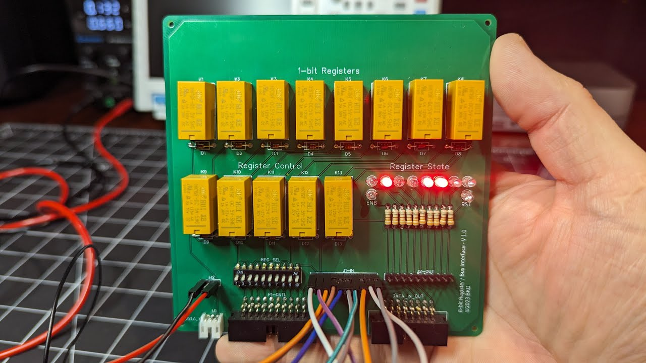
This was my first PCB, and although I was very proud of it, I almost immediately noted that if I was going to need around 15 of these, that was going be a lot of wiring and ribbon cables. I also wasn't happy with the need to send a control signal to clear the register before loading it. Fortunately, Dr. Porter had designed a self-clearing register design, and as for the cables...well...I got my inspiration while watching a video about the IBM 1401 - and it's beautiful card cage!
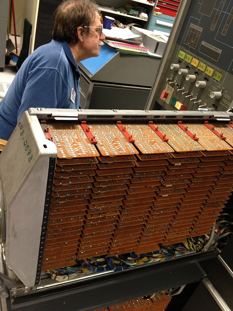
So if I'm going to go with an edge-card, I'll need to know...how many pins will I need?
Discussions
Become a Hackaday.io Member
Create an account to leave a comment. Already have an account? Log In.