-
Summary of several sessions
11/19/2025 at 04:02 • 0 commentsI have made some progress on this project the past month, but I forgot to post an update so here's a quick one. Earlier, I fully tested the circuit with noise gen, VCA, and pink noise filter all together. I use two opamps, one for buffering the smoothed PWM amplitude signal and another for buffering the pink noise output. I added another feature which is a voltage-controlled peak filter at around 150Hz to simulate big waves crashing. The Q of this filter is a little too high to be super realistic but if I assume that the system that's playing it back is pretty shitty then I can justify this high-q as compensating for the shoddy low-end of the speakers ;) (I don't want to re-test a lower Q filter). Anyways, I can use the output opamp for two functions, one is the feedback loop to implement the peak filter, and still behaves like a output buffer. Two birds with one stone.
I've learned two things: it requires me lots of effort to stay on track. While just writing this log I realized that I could reduce the BOM by two resistors, two capacitors and an opamp per channel if I just use the DAC instead of filtering a PWM wave. But the problem is that if you don't fix it then it doesn't work, and I don't want to test this DAC since I know the PWM one works. The drawback is that if later I want to mess around and try some higher frequency amplitude envelopes then I sort of can't, the filter's cutoff is at 1.5Hz. Ba-humbug. The second thing I learned is Seeeduino actually has pretty good supporting materials. I just downloaded some symbol and footprint files from their website and I can easily start designing PCBs. I wonder why I ever drew my own footprints in the past, what a waste of time...
I think I might be getting a little better at this though. The voice in the back of my head is successfully keeping me on track and away from deep rabbit holes. Reading the first post from this sequence also helps re-ground me and remind me why I started this in the first place.
Breadboarding is done, schematic is finalized, code is in a working (read: ugly but functional) state, all thats left is layout and assembly. We're halfway done, ladies and gentlemen!
-
PWM Sine wave generator
10/12/2025 at 06:10 • 0 commentsLast summer I backpacked along the west coast of Vancouver island. Sometimes I look back at the pictures I have of the vast shoreline, massive trees, and unique flora and fauna from that magical landscape. The pictures from that trip are pretty good, but when I really want to re-live those memories and feel like I'm back in my hiking boots, I sometimes listen back to a short 30 second voice memo of waves washing over a pebble beach that I recorded on my phone. This voice memo is one of the tools I'm using to help me along this project.
When looking at the audio waveform of the voice memo, I was looking for the period of the waves (in seconds) and what kind of shape the waves were making. The recording is pretty short, it only captures about 4 waves, and there are really loud pebble-wave sounds that probably make the waveform a little fatter than it should be, but it looks like waves crash at around 5-10 second periods and their shape is surprisingly sinusoidal. That was not what I was expecting, I cannot lie.
Anyways, I had a clever idea for generating the sinusoids on the microcontroller. Since I need the sine wave to move over time, I can just calculate it on the fly using sin/cos relationships! I thought that if I have two variables, one for sin[i] and cos[i], since calculus tells us that d/dt sin = cos and d/dt cos = -sin, then I can calculate the amount they both need to change to get sin[i+1} and cos[i+1]! Now I doubted this would work in practise because it seemed a little too simple, so I made a spreadsheet to quickly test out the idea, and it worked! But I still doubted it would work in practise because of integer precision and under/overflows so I implemented it on my host machine in python, then in C, then in C with integers, and it didn't really start breaking until I forced it to 8 bit integers in C. Here's the main idea:
// I use _ before sin and cos to avoid redefining symbol errors

uint16_t scale_nom = 1;
uint16_t scale_denom = 60;

// scale = scale_nom / scale_denom; // (I'm avoiding floats!)

// initial conditions
uint16_t _sin = 0x7000;
uint16_t dcos = (int32_t)_sin * scale_nom / scale_denom;
uint16_t _cos = 0;
uint16_t dsin = (int32_t)_cos * scale_nom / scale_denom;

// iteratively increment values with their deltas.
for(int i = 0; i < n; i++) {
    _sin += dsin;
    dcos = -(int32_t)_sin * scale_nom / scale_denom;
    _cos += dcos;
    dsin = (int32_t)_cos * scale_nom / scale_denom;
}
GIven:
Assuming its the first iteration, the first line in the for loop updates sin by 0. Then, line two calculates dcos, or how much cosine will change next. dcos is equal to -sin times a small change in time, and I use a fraction scale=scale_num/scale_denom where scale_demon >> scale_num for smooth outputs. After updating dcos, we can increment cos += dcos, and lastly calculate dsin from cos * the same scale.
In my code, I call dt `scale` and calculate it as `scale_num / scale_denom`.
The effect of the scale on the output is that the smaller scale is, the smoother the output will be, and at the same time, the longer the period. I discovered some interesting behaviours when testing out this piece of code. The algorithm often overshoots the initial condition, so I give it a little headroom (0x7000 instead of 0x7fff). Additionally, cranking the scale to be not-so-small (over 0.5) makes it overshoot more, so for real sines its best to keep scale<0.5 but out of curiousity I tested what would happen if we cranked it above 1. For a while, it looks ok, but then after around 2 it starts looking pretty chaotic.")
Signal and FFT when scale = 1/60 (0.0083). Nice and clean! 
Signal when scale = 1.6. Starting to get a little deformed. 
Signal when scale = 1.95. Uh oh! 
Chaotic signal at scale = 2.03 
Chaotic Signal and FFT when scale = 2.05. The noise has a pretty gnarly frequency profile so it would probably not make for a good noise source. But it may sound good for nasty metallic drums, or something like that. 
Chaotic Signal and FFT when scale = 4.32. Compared to the plot at 2.05, this one has a little smoother noise, so it may sound a little less harsh (relatively). I'm sure it still sounds pretty painful though. I think the Chaotic output arises from the integer under/overflows since when I tried cranking the scale >1 while using floats, not ints, the magnitude of the sine wave just blows up, no chaos. I didn't do any further analysis on the output to see how random it really is, because I don't think this is going to replace my shift-register noise gen (which I know works and is really white). I'm pretty happy with what I discovered here and I kind of want to hook it up to a knob and play it like a wavetable to hear what it sounds like!
Anyways, till next time!
-
Swing-Type VCA
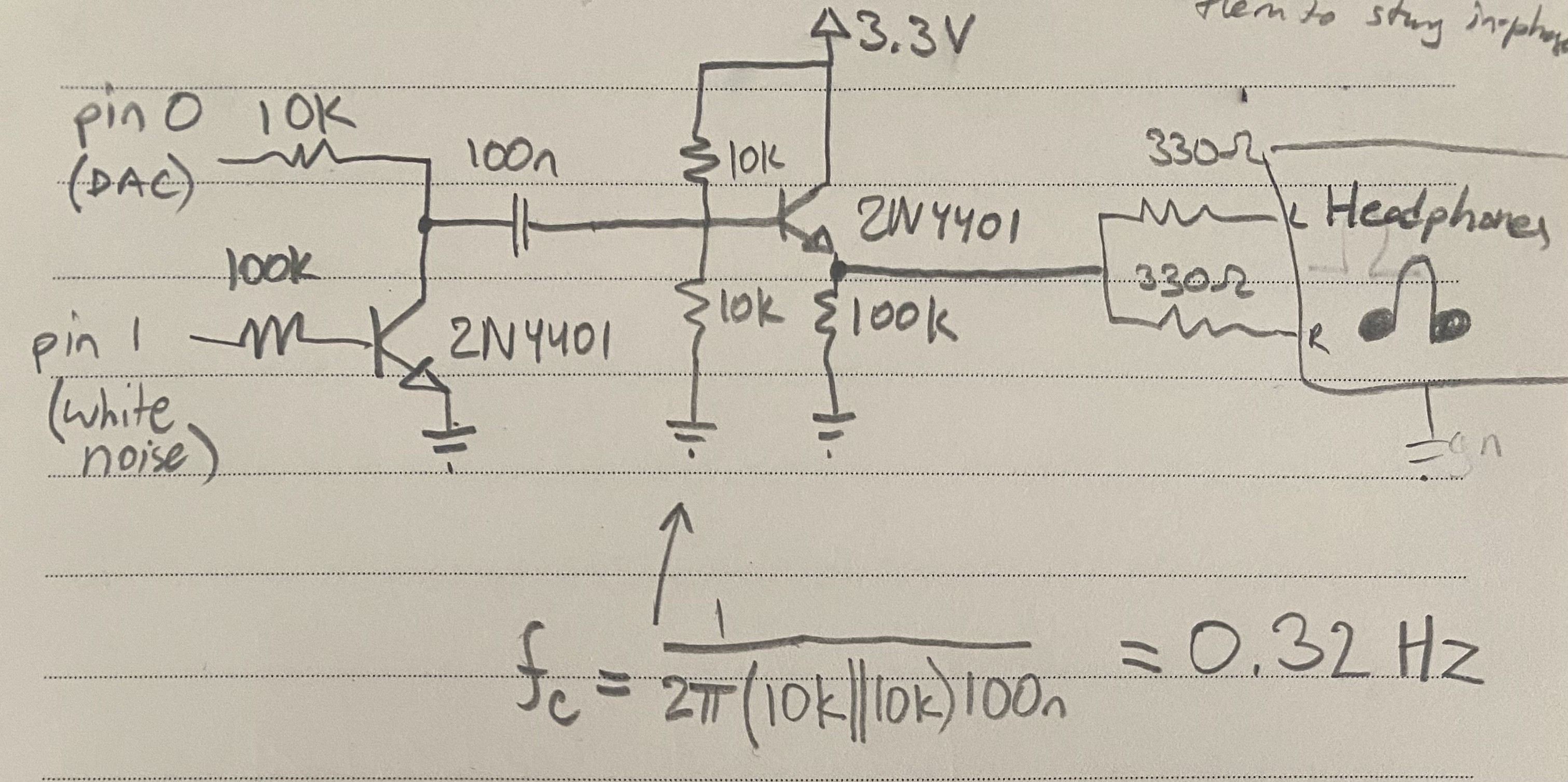
10/04/2025 at 20:25 • 0 commentsToday I programmed the DAC on my Seeeduino XAIO SAMD21 to output a slow triangle (ish) wave and used that signal to modulate the amplitude of the white noise. I used a swing-type VCA as shown below, which is rarely used because it heavily distorts (clamps) the input signal, but in this case the input signal is already a square wave so its perfect for this application. I coupled the output through a capacitor, and biased the input transistor at half the rail voltage (written 3.3, but its actually 5V from the USB-C cable, pin 14) Honestly, after looking at it again I don't think this is optimal nor necessary, I could've just buffered it straight and coupled the output to the headphones. Also right now, the output to headphones would be floating around 2.5V, and the headphones ground is 0V, so there will be a hefty DC bias on the headphones, which may not be ideal. I didn't head any pops or clicks when connecting though, so maybe its ok. Improvements needed, but it works.
Next time I will try improving this circuit and improve the Arduino code as well. I'm thinking of making 2 pink noise sources (Waves R+L) and 2 white noise sources (wind R+L), meaning 4 amplitude CVs, so I will need to try PWM CV instead of DAC. WInd source should reach around 4Hz for details but otherwise around 10-20s period. Waves around 10s period with a little swell shape __...-~-...__
uint8_t downscale = 2; // Called in timer ISR, around 93KHz void do_analog() { static int8_t delta = +1; static uint16_t y = 0; y += delta; if(delta == +1 && y == (1 << (10+downscale)) - 1) { delta = -1; } if(delta == -1 && y == 0) { delta = +1; } analogWrite(0, y / (1<<downscale)); }![]()
-
First log of many
10/03/2025 at 01:56 • 0 commentsI was about to give up for the day on this project. Just after compiling and uploading, my VS Code was using up all my CPU and slowed my whole system to a near halt. Since my music also stopped, I pulled out my phone (brutal mistake) and connected to Spotify. I briefly glanced at my YouTube home page and nearly got sucked into endless scrolling, functionally calling the productive session to a close. But I remembered the conversation I had with my coworker earlier today: the goal is to actually finish this project. Immediately, I new what I had to do. I needed to stop trying to figure out a new development environment in VS Code that would allegedly give "lower level control" and other false-benefits, and crack open the old dusty Arduino IDE and just get 'er done!
Today around lunchtime, I got a notification on my phone. The package I ordered from Digikey -- nothing fancy, just some simple microcontrollers and a few other nicknacks -- was delivered to my house. For the rest of the day, I was hopping in my chair and itching to tell anyone about my new embedded project I had waiting for me at home. The main sentiment that I shared in today's conversations was that I never complete projects, and this time that would change. The usual reasons I don't complete projects are because the goal of the project is to have fun learning about the topic, I allow myself to get sucked into niche technical problems, and enjoy the challenge of figuring out how things work under the hood. Ultimately, this exploratory mindset results (for me) in lots of deep-dives into rabbit holes that are interesting in the short-term, probably further my understanding of the topic at hand but don't actually really make any progress to completing the project. This is all fine and good for a while, but after spending, like, 6, 7, years with technical hobbies and the only thing to show for it being a cheeky "I learned a lot of stuff", it leaves a little more to be desired. Now I am driven to build something by sheer lack of past results, start to end, have it work, be able to show it off and prove to myself that I have follow through. And the project that I will do this with is a pink noise relaxation device, the one I started with this blog post nearly a year ago.
The main ways I will actually complete this project:
- Tell everyone I know that I am working on it and that I will finish it to stay accountable (outsourcing, to some degree :) )
- Do the least effort to get the best result. Prioritize WORKING over PRETTY/FAST/OPTIMAL/whatever.
- Don't get bogged down with nonsense.
- Pick the tried and tested tools for the job that will get it complete quickly before I burn out.
- Have clear goals, measures of success, deadlines. Reject feature creep.
- Don't go off on exploratory tangents to figure out how something works.
- If it ain't broke, don't fix it <---- SUPER IMPORTANT!!!
Today, I booted up Arduino IDE, vibe coded a timer register setup, stole my own LFSR code from a year ago, and listened to the resulting white noise through two series 330 ohm resistors into cheap (disintegrating) wired headphones. Does it work? Yup. Am I proud of it? Not yet. Will this work style result in a real finished product some day? Only time will tell...
Pink Noise Generator
Digital white noise with an analog "pink" filter
")