 madhead
-
1Preparation
Prepare all necessary components and tools.
There are numerous ways to assemble this project, and the required components vary depending on your approach. For example, you can directly connect the pump to the controller using a pair of crimped wires, or you might opt to link the controller with a socket, allowing the pump to be connected without rewiring by utilizing its plug. To construct this control box, you may need to acquire additional parts, such as a socket and a 3D-printed housing. Alternatively, you could house the controller in a flush-mounted box or use both a box and a 3D-printed housing. It's also feasible to incorporate a manual bypass (i.e., the capability to operate the pump using a conventional switch). For this, an extra piece of wire and a switch will be necessary. Consult the list of components provided here as a starting point.
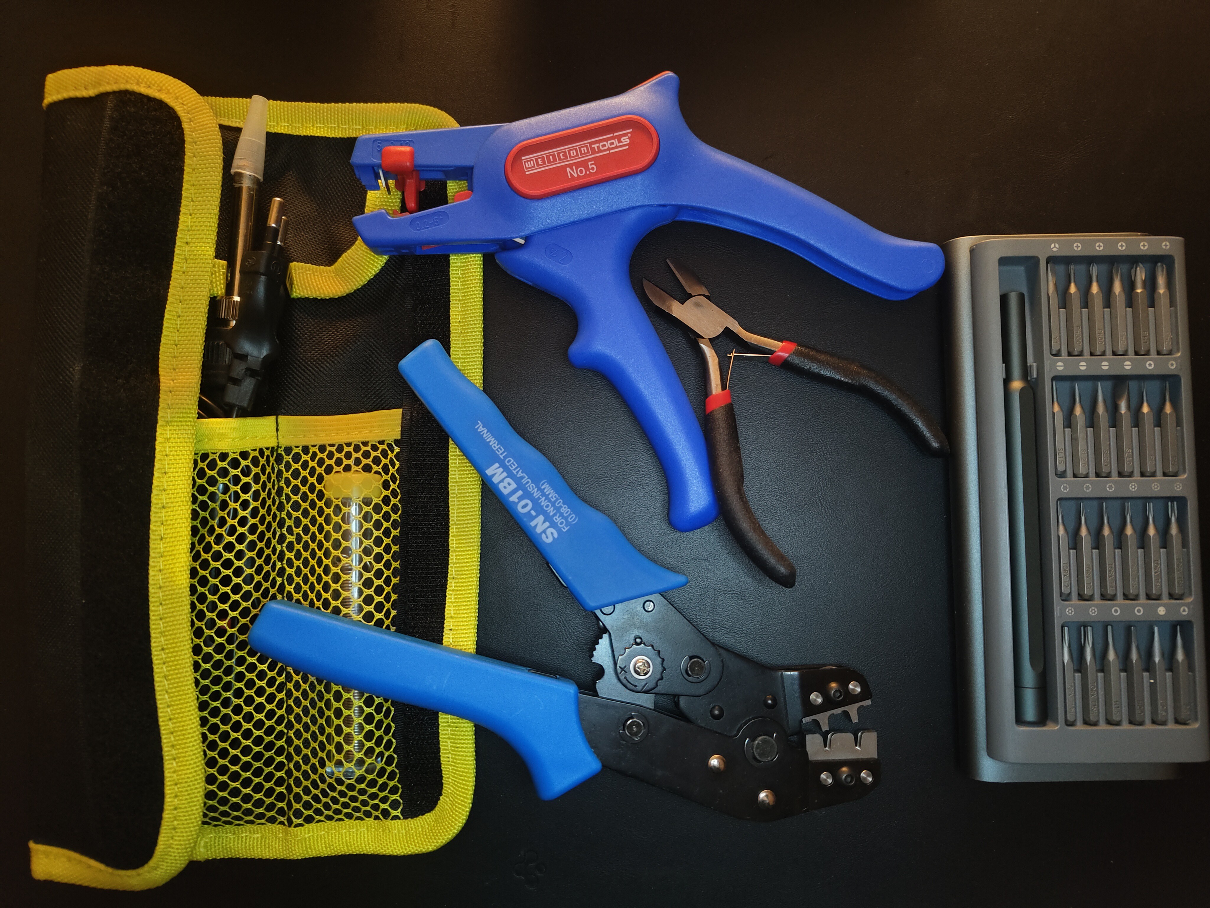
For the tools, you'll need:
- A soldering iron, solder, flux, etc.
- A screwdriver
- A wire-cutting multi-tool or a knife
- A JST crimper tool is highly recommended to have
-
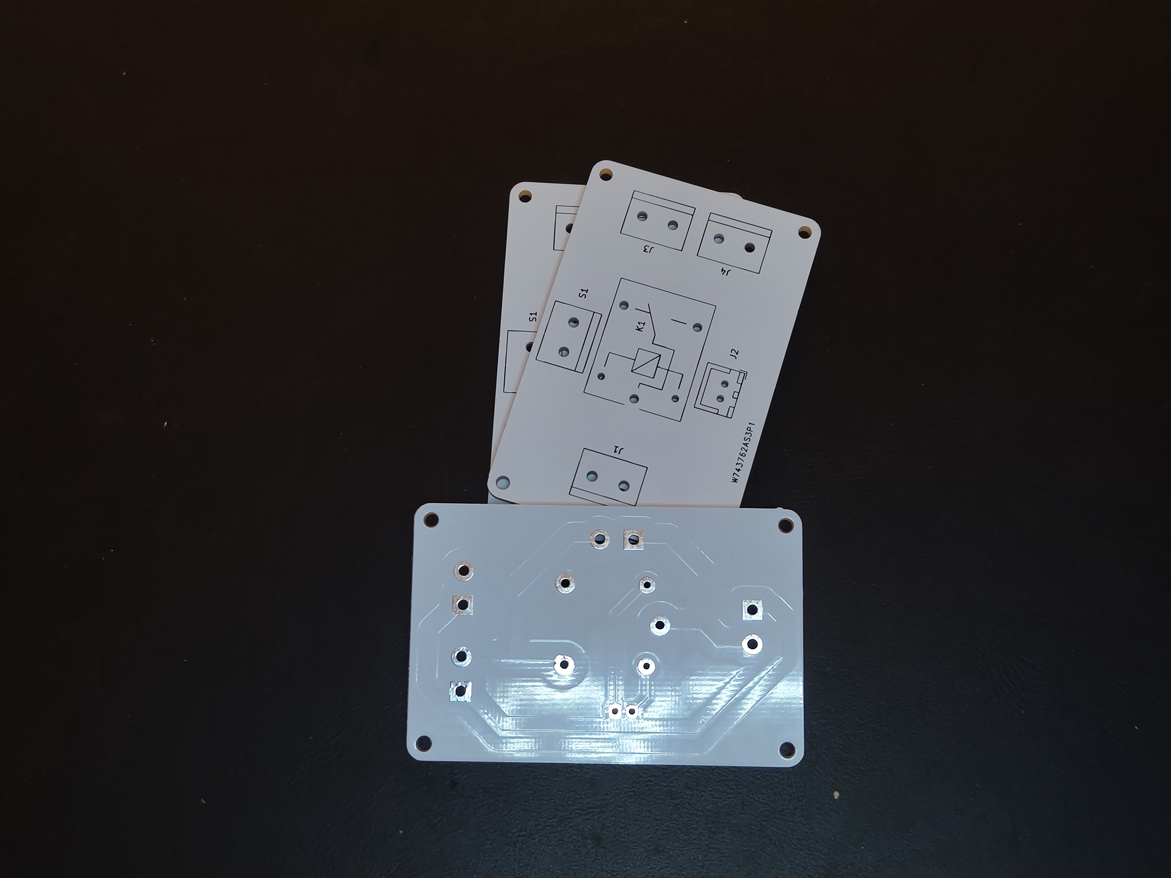
2Making a PCB
This is the V1 of the controller, having two outputs. Later I decided to leave only one.
While you could opt for point-to-point connections, utilizing a Printed Circuit Board (PCB) offers a more reliable method for assembling the electronics.
For those without any prior experience, the simplest way to obtain a PCB is to employ a service such as JLCPCB or PCBWays. I personally have experience with the latter. Simply upload the
controller.zipwith the Gerbers and you should receive your PCB shortly.Alternatively, if you're up for the challenge, you can manufacture the PCB yourself, even with your 3018 CNC machine! Use the provided Gerber files and the schematic for your guidance.
-
3Soldering the PCB
If you opted not to use a service for PCB assembly, the responsibility falls on you. Simply go ahead and solder it yourself.
-
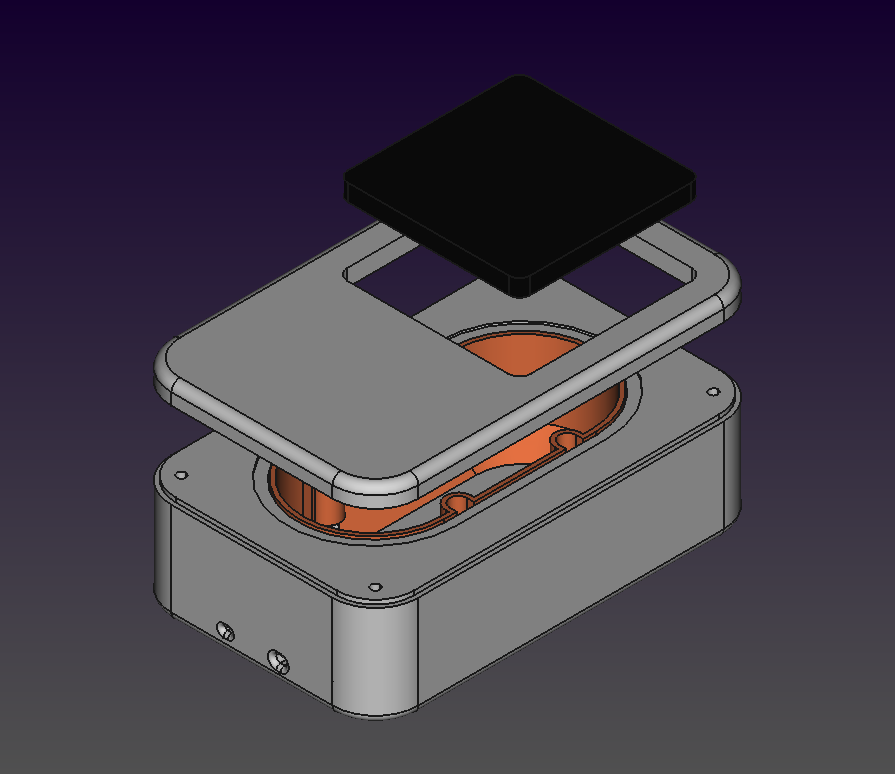
4Making a controller enclosure
I opted for a double-slot flush-mounted box (orange) as the foundation for my enclosure. One slot accommodates the freewheeling PCB of the controller, while the other is utilized as intended: it houses a socket (black). The enclosure is made up of a base and a lid, which are fastened together with screws.
Automatic Air Assist for 3018 CNC
Automatic air assist with an external mains-powered air pump
Discussions
Become a Hackaday.io Member
Create an account to leave a comment. Already have an account? Log In.