-
Connectivity!
01/20/2017 at 21:06 • 0 commentsSo far I have described how the camera can be used standalone, using the shutter release button to take a photo. A feature of the previous model was serving a web page to allow pictures to be taken and stored photos to be reviewed. I have done something similar here. In the last log entry I mentioned the combined Wifi/Bluetooth USB adapter. This particular model is able to act as a client and station (AP) at the same time. In the video below, I start by pinging an IP on my home WLAN (192,168.1.3). As the Pi boots, it first gets the camera running (indicated by the green light), then connects to the WiFi. This can be seen when the camera starts returning a ping.
After this I scan for available wireless networks, one called 'Camera' is found. At this point I could connect directly to this network and access the web interface at 192.168.0.1 as if I was out and about and using the camera away from home WiFi. For demonstration purposes, I'm going to continue and access the interface at 192.168.1.3
The interface is very simple and consists of four buttons along the top:
- Download - view full size version of the picture. Only thumbnails are shown in the gallery for speed
- Take Photo - self explanatory
- Delete - delete the photo currently shown
- Print - I'll get to this in a minute
The interface is using the lightweight library from http://fotorama.io/ with a few jquery bits for the buttons. I'll hopefully get around to making the source available when I get on to the software write up later on.
Selfie Button
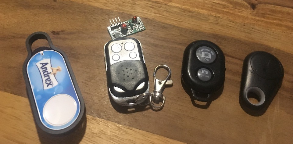
One feature I wanted was to be able to take a group selfie with remote shutter release. I had lots of ideas around this, a few of which are shown below
![]()
- Amazon Dash Button - It works. It's quite straight forward to detect when this connects to the camera's wifi but a bit slow and takes a while to reset and be ready to trigger the next photo.
- 433MHz Keyfob and receiver - again, it works but range not great and requires an extra piece of hardware squeezing in to the camera.
- Cheap Selfie Shutter - This works over Bluetooth and presents itself as a HID Keyboard. It works fine when right next to the camera but when it is on the edge of it's range (which is only about 2 metres in this setup), it starts to act erratically taking multiple seconds to send the command, repeating commands. Good when it works but not reliable.
- Another cheap Bluetooth button - Not sure what this is or how it works as I've only just acquired it. Only cost 99p so not expecting much, but we'll see.
I also considered an Infrared receiver but I would have to find somewhere for it and I'd already completed the wiring to the camera module and indicator/flash panel which would seem the obvious place for it.
So, I went the DIY route!
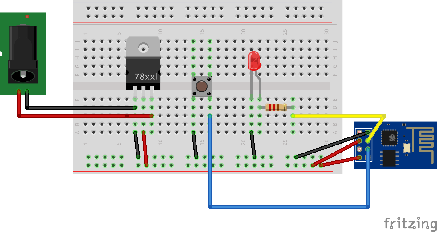
The Dash button was the most reliable and had the best range but was unsuitable because of the lag and the delay on repeated button presses. I'd used ESP8266 WiFi modules before so had a few lying around and thought they might be suitable. All that is required is to connect to an AP and call the URL http://192.168.0.1/takephoto.php when a button is pressed - easy!
I was going to use the ESP01 module due to it's cheapness and smallness. I wired it up as below, loaded the code on to it using the Arduino IDE and it worked like a charm!
![]()
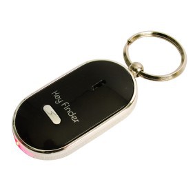
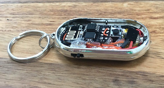
#include <ESP8266WiFi.h>
#include <ESP8266HTTPClient.h>

HTTPClient http;

void send_event(const char *event);

// Wifi setup

const char *ssid     = "YOUR_SSID";
const char *password = "YOUR_PASSWORD";

// Hardware setup
const int buttonPin = 0;     // the number of the pushbutton pin
const int ledPin = 2;        // the number of the LED pin

// Variables will change:
int buttonState;             // the current reading from the input pin
int lastButtonState = LOW;   // the previous reading from the input pin

// the following variables are long's because the time, measured in miliseconds,
// will quickly become a bigger number than can be stored in an int.
long lastDebounceTime = 0;  // the last time the output pin was toggled
long debounceDelay = 50;    // the debounce time; increase if the output flickers

void setup()
{
  // Set your pin modes
  pinMode(buttonPin, INPUT_PULLUP); //enable internal pullup resistor so we don't have to provide our own
  pinMode(ledPin, OUTPUT);

  // Bring up the serial for a bit of debugging
  Serial.begin(115200);
  delay(10);

  // We start by connecting to a WiFi network
  Serial.println();
  Serial.println();
  Serial.print("Connecting to ");
  Serial.println(ssid);

  WiFi.mode(WIFI_STA);
  WiFi.begin(ssid, password);

  // Wait for the connection, flashing the LED while we wait
  int led = HIGH;
  while (WiFi.status() != WL_CONNECTED) {
    delay(200);
    digitalWrite(ledPin, led);
    led = !led;
  }
  digitalWrite(ledPin, LOW);

  Serial.println("");
  Serial.println("WiFi connected");
  Serial.println("IP address: ");
  Serial.println(WiFi.localIP());
}

void loop()
{
  // read the state of the switch into a local variable:
  int reading = digitalRead(buttonPin);

  // check to see if you just pressed the button
  // (i.e. the input went from LOW to HIGH),  and you've waited
  // long enough since the last press to ignore any noise:

  // If the switch changed, due to noise or pressing:
  if (reading != lastButtonState) {
    // reset the debouncing timer
    lastDebounceTime = millis();
  }

  if ((millis() - lastDebounceTime) > debounceDelay)
  {
    // whatever the reading is at, it's been there for longer
    // than the debounce delay, so take it as the actual current state:

    // if the button state has changed:
    if (reading != buttonState)
    {
      Serial.print("Button now ");
      Serial.println(HIGH == reading ? "HIGH" : "LOW");
      buttonState = reading;

      // When the button is in the LOW state (pulled high) the button
      // has been pressed so send the event.
      if (buttonState == LOW) {
        send_event("button_pressed");
      }
    }
  }

  // save the reading.  Next time through the loop,
  // it'll be the lastButtonState:
  lastButtonState = reading;
}

void send_event(const char *event)
{
  // set the LED on whle we are sending the event
  digitalWrite(ledPin, HIGH);

  if(WiFi.status()== WL_CONNECTED){   //Check WiFi connection status
    // Make a HTTP request
    http.begin("http://192.168.0.1/takephoto.php");
    http.addHeader("Host", "raspberrypi:8080");
    http.addHeader("Content-Type", "text/plain");
    int httpCode = http.GET();
    String payload = http.getString();
    Serial.println(httpCode);   //Print HTTP return code
    Serial.println(payload);    //Print request response payload
    http.end();
  }
  // Finished sending the message, turn off the LED
  digitalWrite(ledPin, LOW);
}
I then had to build it into an enclosure. After a bit of searching, a 'locate your keys with a whistle' device seemed like it might fit the bill.
It had an led, a button, an on/off switch, hopefully enough space for the ESP and the battery and was only 99p!![]()
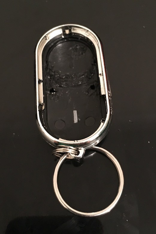
I opened it up and removed all the support structure to leave just the bare shell
![]()
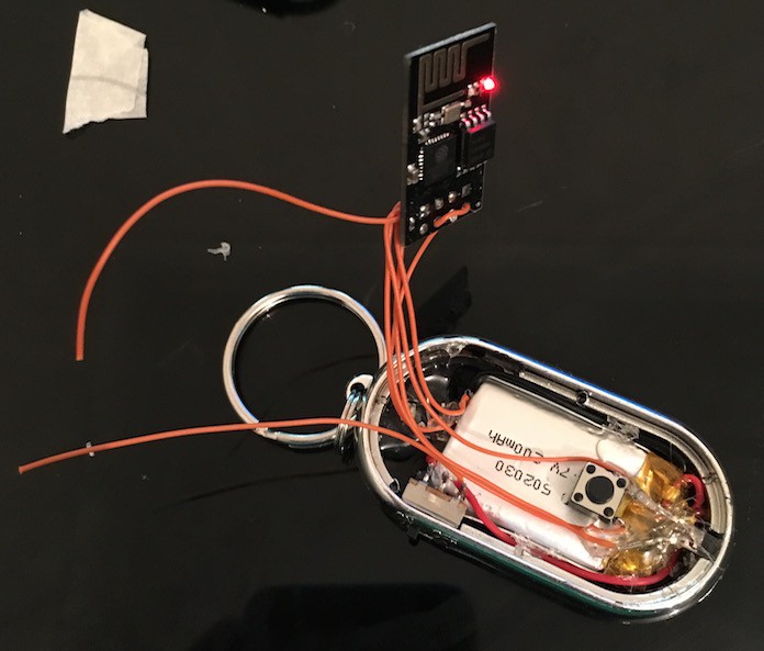
I removed the switch, LED and button from the original circuit board, then used them along with a 200mAh battery that I scavenged from a promotional video Christmas Card to build the circuit I prototyped within the body of the keyfob.
![]()
The 2 wires not attached to anything are for charging the battery. When the switch is off, the ESP is disconnected and the battery can be charged.
The 3.3v regulator is in the recess on the left and the led is back in the original position on the right.
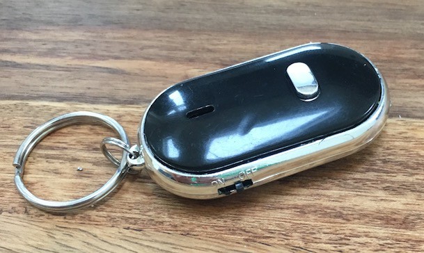
The finished article:
![]()
![]()
The Printer
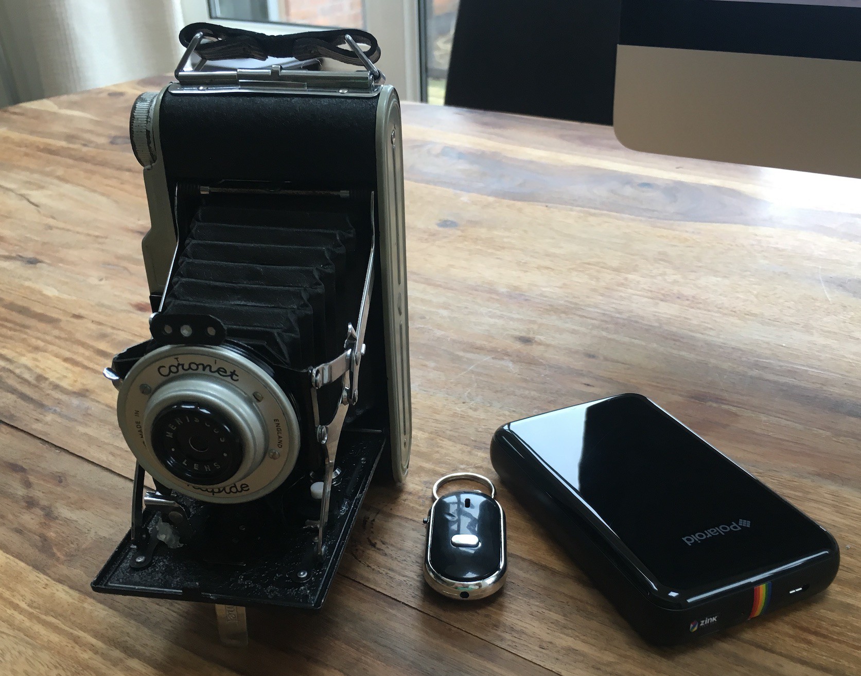
One of the features I wanted out of the camera was to be able to print the photos while on the move. This was, obviously, the best feature of the Polaroid and one that I missed with the Box Brownie set up.
There are not many options for mobile photo printing and the obvious choice seemed to be one of the little printers that use the Zink printing technology. There are a few of these LG and HP make one but I went for the Polaroid Zip as it was the same price as the others but I had read about someone being able to print to it from the linux command line.
![]()
This turned out to be true. Using a tool called ussp-push I am able to send images to the printer and get them in my hand a minute later.
-
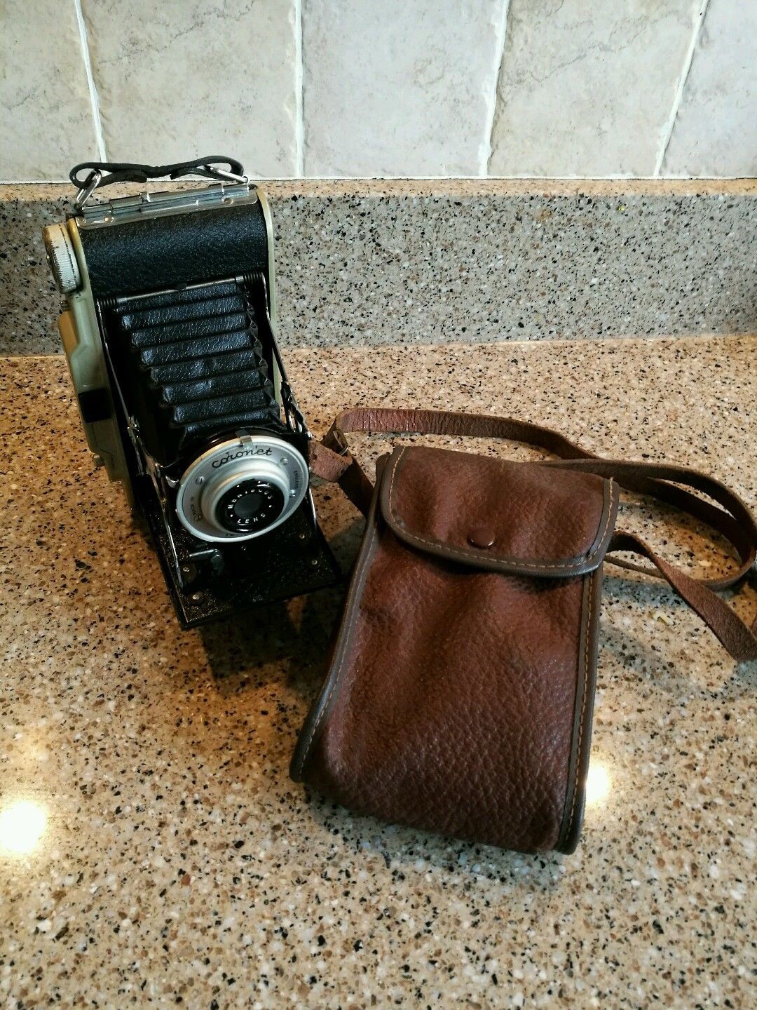
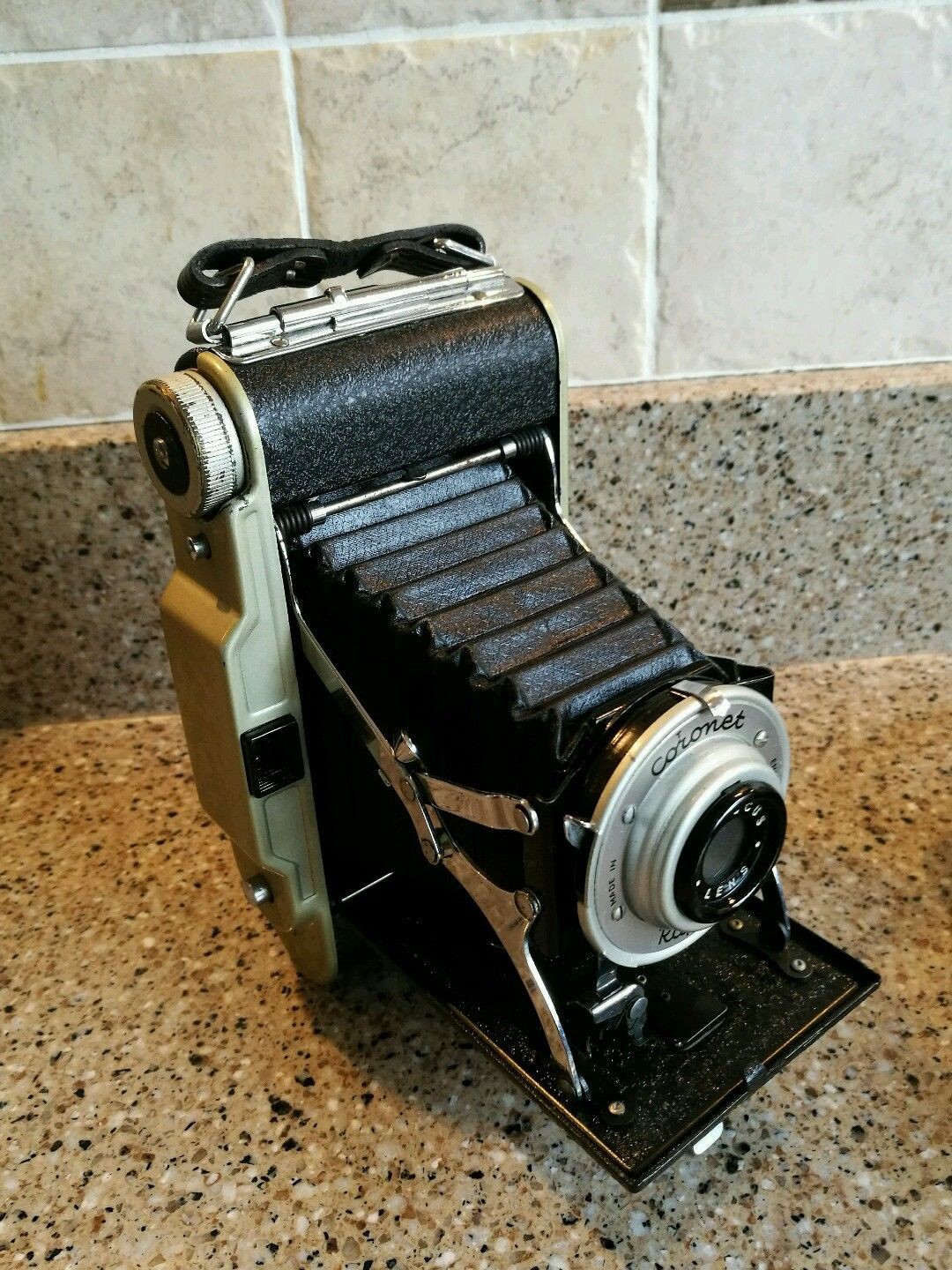
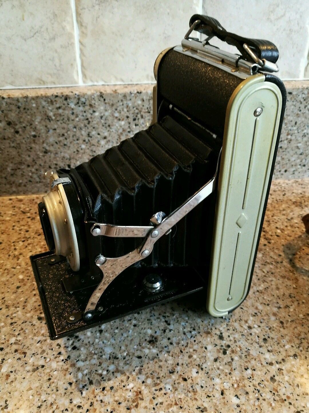
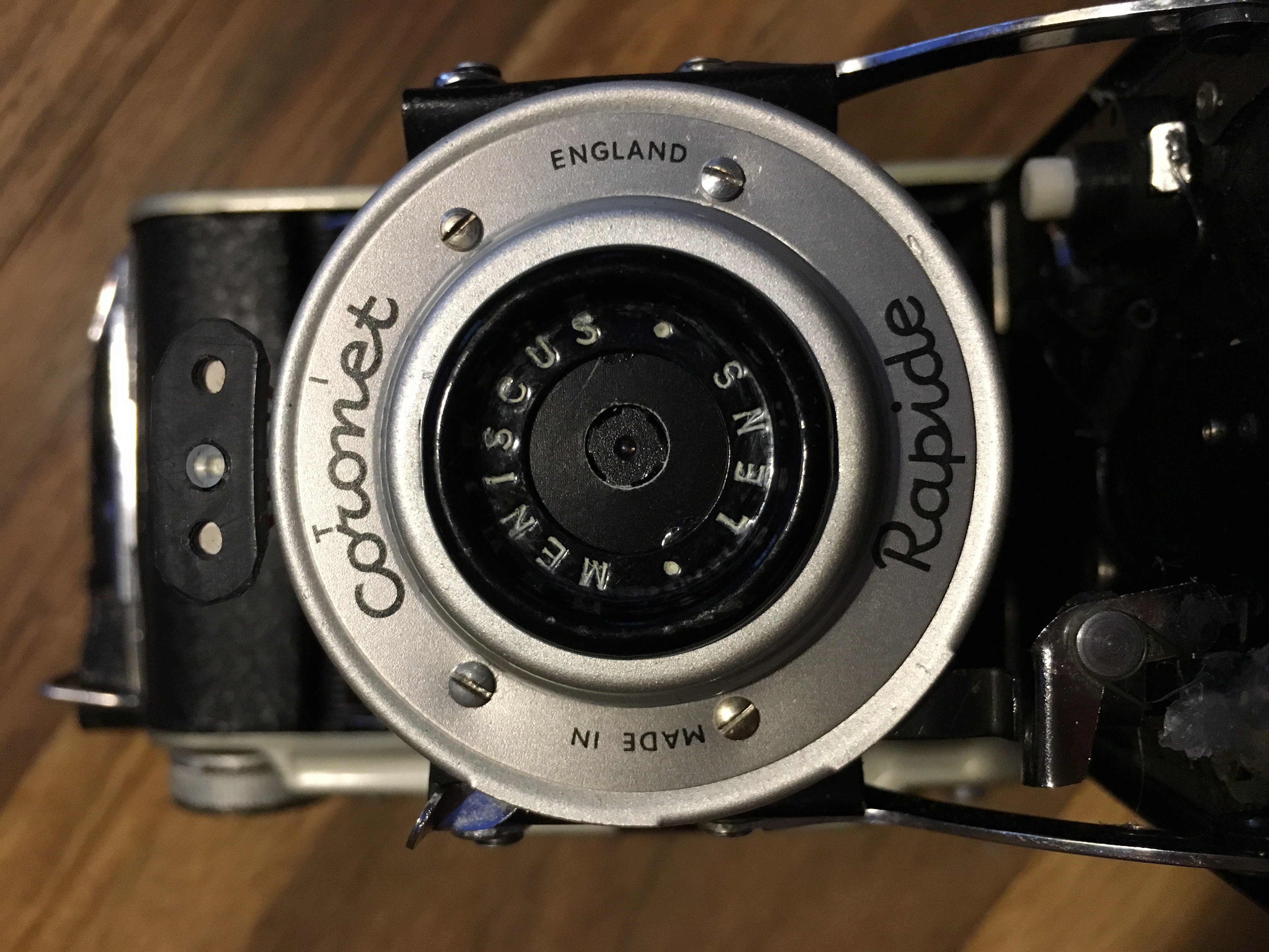
Folding Camera - Coronet Rapide
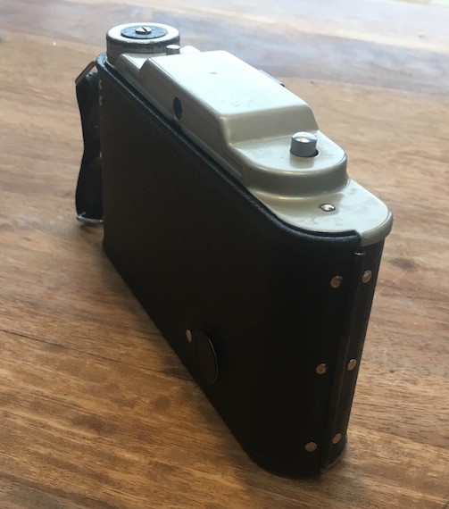
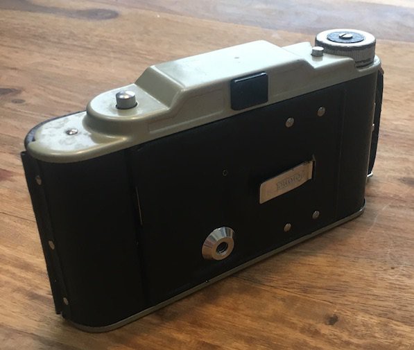
01/20/2017 at 16:14 • 0 commentsFor the next instalment, I wanted a more interesting original camera/enclosure. Thanks to good old eBay I found a folding camera called the Coronet Rapide from the late 40s/early 50s that looked cool and was in my price range - It cost me the princely sum of £9.99 (plus postage).
![]()
![]()
![]()
![]()
![]()
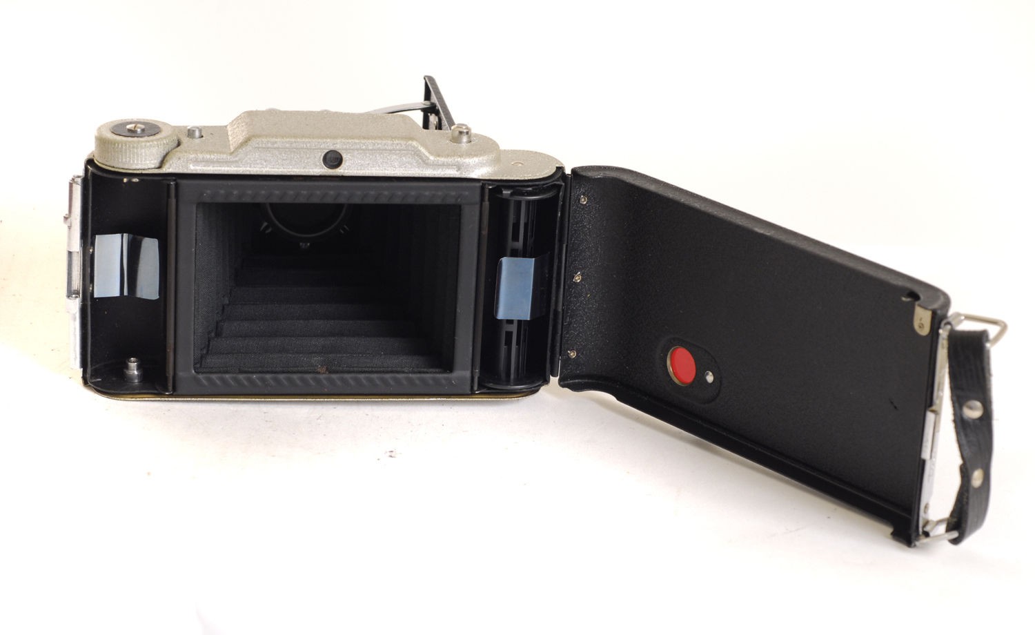
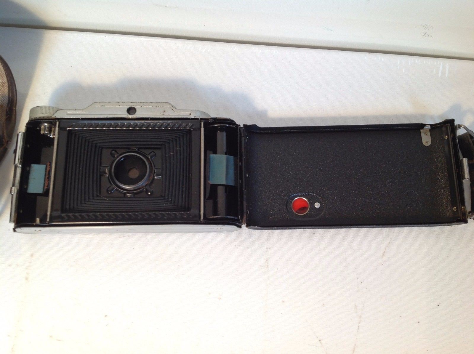
I wasn't sure of the dimensions of the camera but I was hoping that I could fit cylindrical power cells of some type into the two sides where the film used to fit and have room for a Pi Zero to lie flat between the collapsed bellows and the rear case. I also hoped that the lens/shutter assembly would have enough room to house the camera module. Some of these things happened others didn't quite work out that way, read on for more info on that.
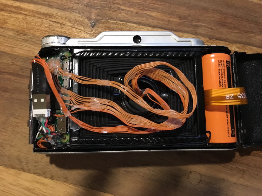
Power
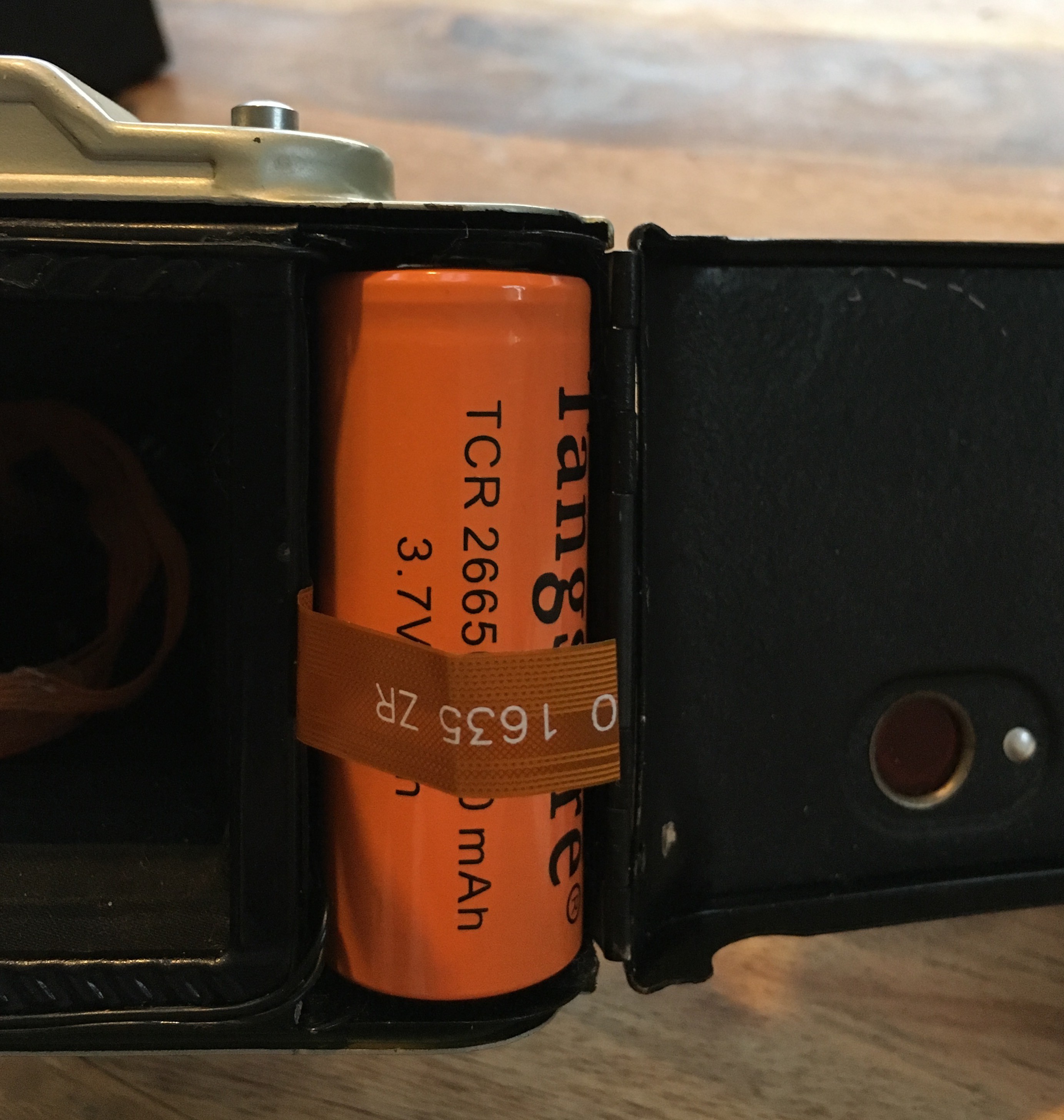
Luckily, as I'd hoped, the recesses that were originally designed to hold the 120 film were a perfect fit for a 26650 Lithium Ion cell. The ones I used have an integrated protection circuit to protect them from short circuit, overcharge and over discharge. I fashioned some contacts out of some of the springy metal found in a used film pack from the Polaroid camera and fixed them in position with a little hot glue (LOTS more of that coming up). I also used a piece of ribbon cable to make a battery release tab which I attached to a conveniently located hinge that used to support the film spool. As there is no integrated charging functionality and I wanted to make the batteries replaceable, this makes it really easy to swap them out.
![]()
![]()
The battery is wired via a mechanical switch to a 5v boost module, this one to be exact. I chose it mainly because of its high power output (it was going to be supplying a Pi, WiFi + Bluetooth Dongles plus a Flash of some sort so 3A should cover it).
![]()
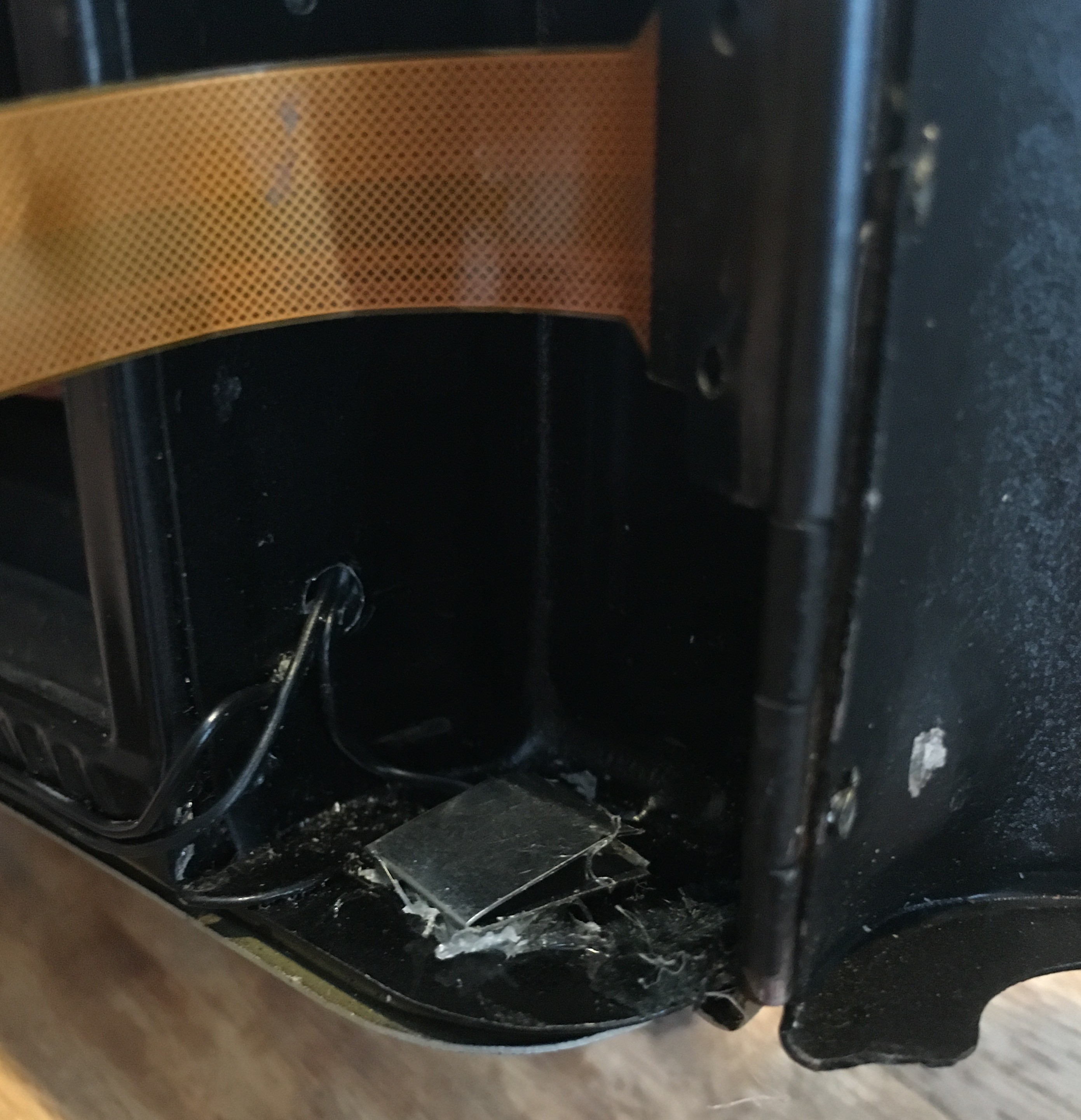
This switch was 'borrowed' from a magnetic LED work light. I used other microswitch types but they weren't sturdy enough. This one will stand up to a good amount of use. It is mounted (via hot glue!) in such a position that it doesn't get in the way of any of the mechanics of the bellows system and nestles in a void when the camera is closed. Due to some design changes during the project,, the switch cuts the ground line rather than the conventional live but electrically it makes no difference.
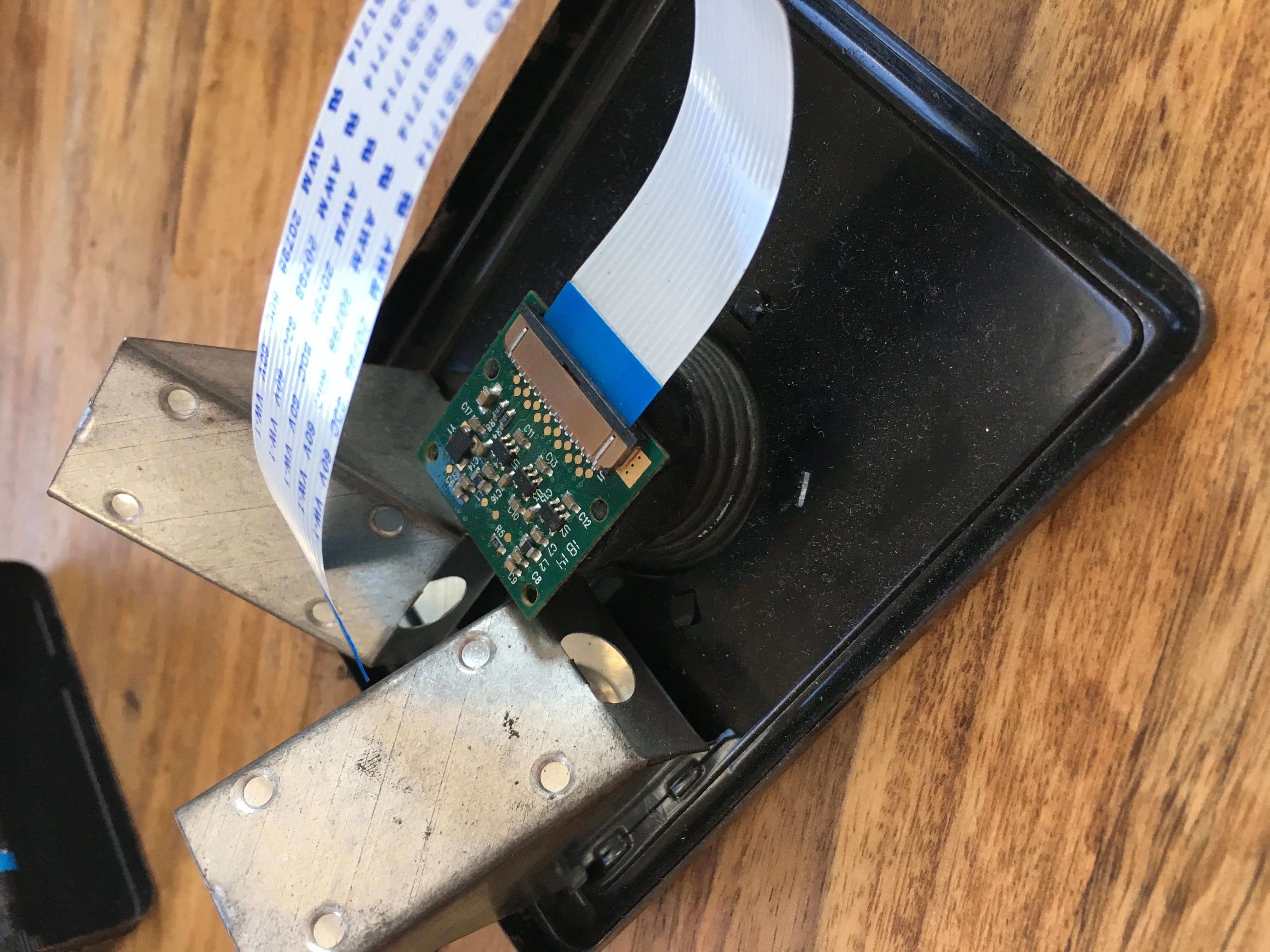
The Camera Module
![]()
My luck was in again as the camera module was an almost perfect fit for the lens assembly and I could leave most of the original shutter mechanics in tact. I had to file down the corners of the module's PCB slightly to improve how it sat and I used a disc of black card to tidy up the front and hide the board from view. More hot glue to secure it in place and I was done.
![]()
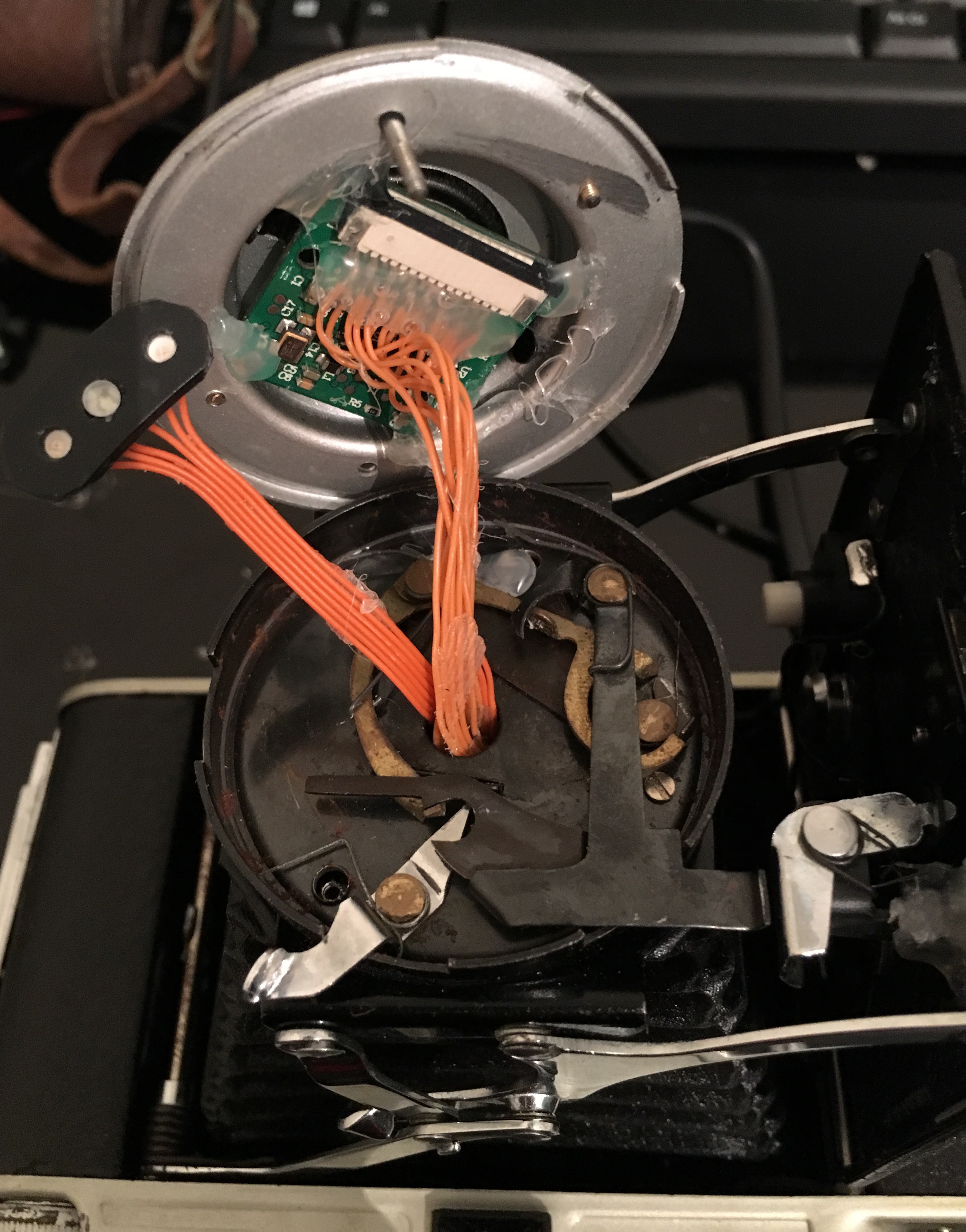
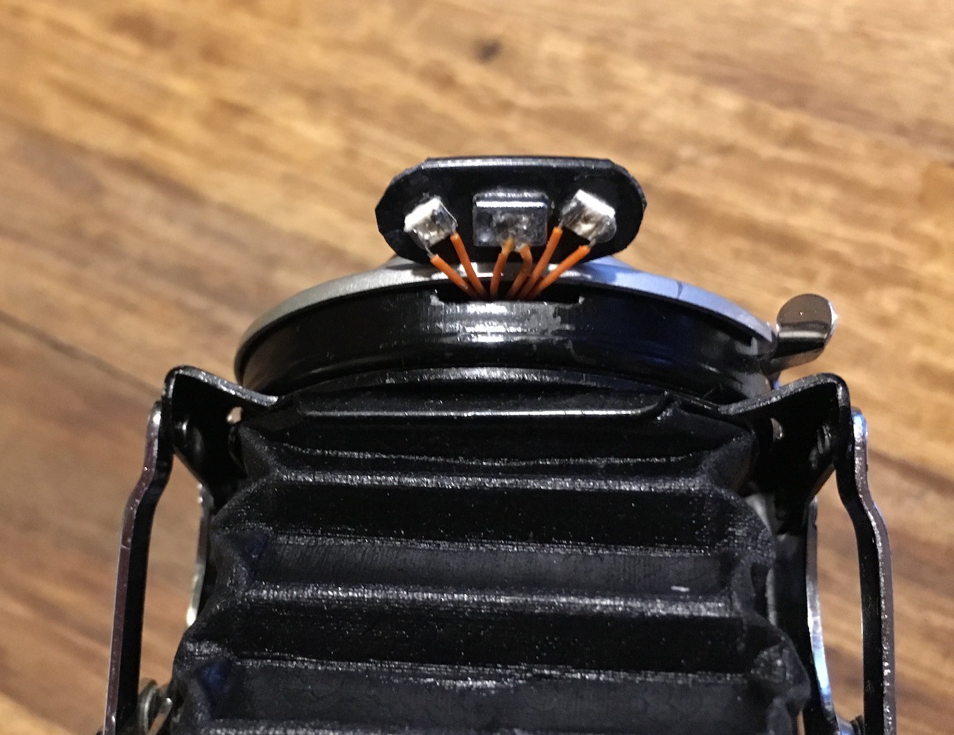
You might be wondering what the orange wires soldered to the camera module are for? Well, my original plan was to use the normal ribbon cable that is required to connect a camera to the Pi Zero but this was not long enough. I then tried the 30cm version of the ribbon cable and while this was long enough, it was not flexible enough to handle all the twists, turns and movement that would be required so I was forced to solder all 15 pins myself. This was simple enough at this end as the camera module has convenient solder pads for each of the pins (visible in the image below), but soldering the other end was a different story (more on that later)
![]()
The other part you may be wondering about is the black bean shaped thing with the 3 LEDS on it. This is my solution to the flash and status indicator problem. It is made up of two SMD LEDS, one green one blue, taken from an RGB LED strip I had an off-cut of and a flash LED in the middle. The flash LED was taken from an old iPhone 5c that had a failed mainboard so was otherwise useless.
![]()
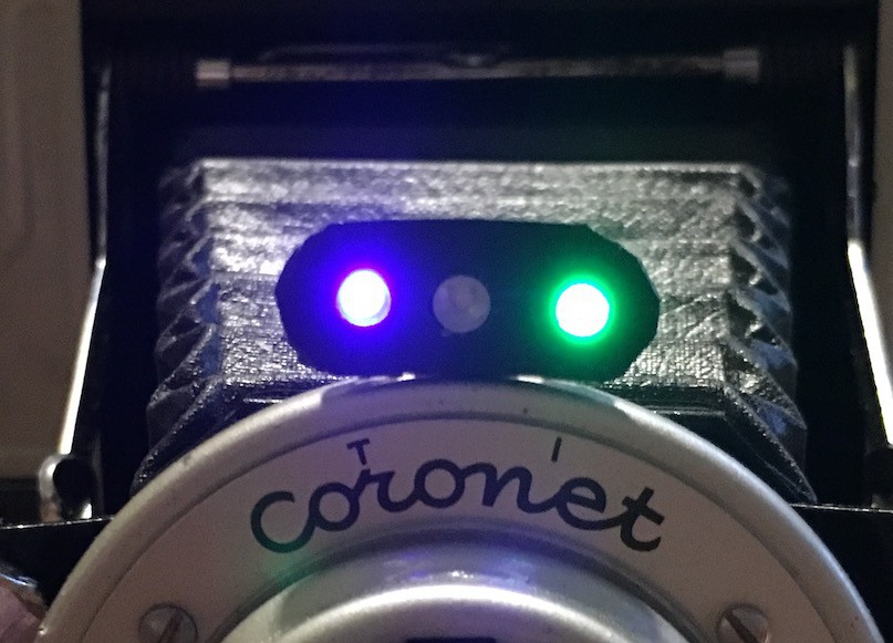
![]() The cutting/shaping of the black plastic isn't as neat as I'd like, but it does the job. The blue LED is lit when the Pi has power (it runs of the constant 3.3v from the GPIO connector) and the green LED lights when the camera is ready (it is connected to a GPIO pin that is controlled in the python script)
The cutting/shaping of the black plastic isn't as neat as I'd like, but it does the job. The blue LED is lit when the Pi has power (it runs of the constant 3.3v from the GPIO connector) and the green LED lights when the camera is ready (it is connected to a GPIO pin that is controlled in the python script)The Shutter Release Button
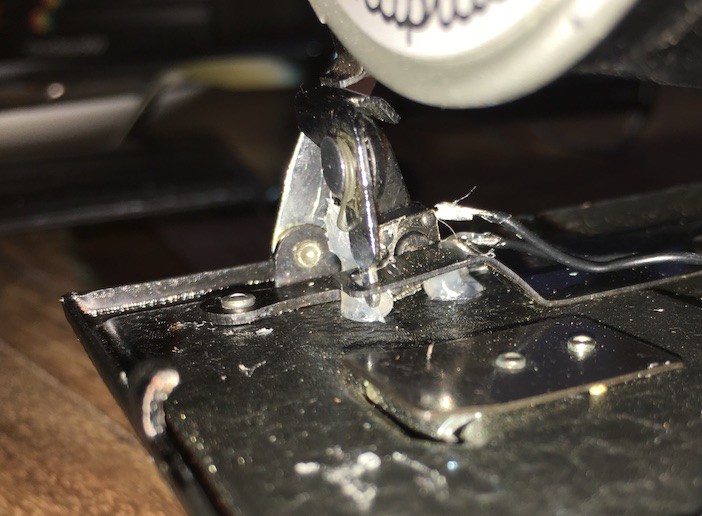
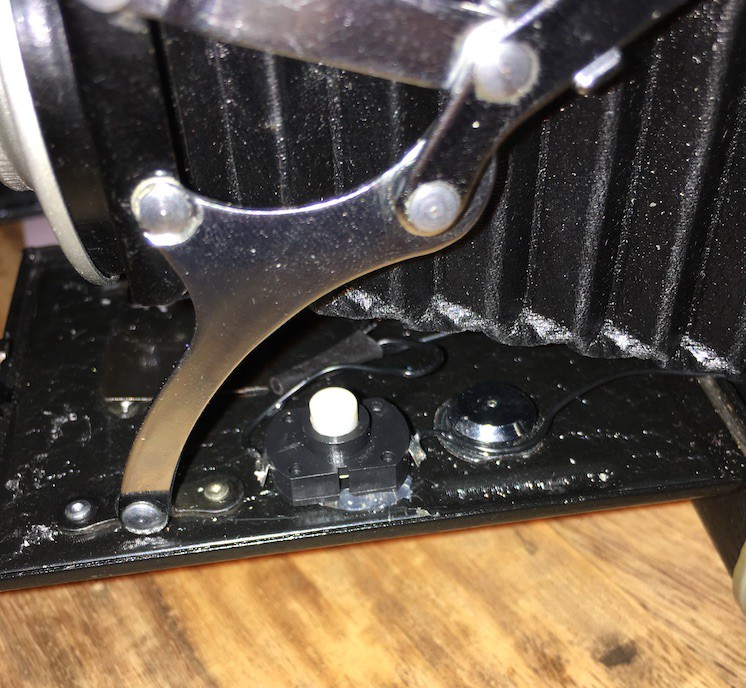
The camera has a manual shutter button which meant it was easy to insert a microswitch in the mechanism. This is connected to a GPIO pin on the Pi and means I can use the original shutter button to take a photo.
![]()
The Raspberry Pi (V3)
When the Pi Zero was announced I knew I was going to put one in a camera. 2 problems:
- The 2 versions did not have a camera connector
- I couldn't hold of one for love nor money
Thankfully, I managed to get one of the first batch of V3s and embarked on this project.
The recess on the opposite side to the battery compartment, where the film take up used to be, is 71mm by 26mm diameter. The dimensions of the Pi zero are 65mm (68mm including the mini SD card) by 30mm. This was going to be a tight fit.
Unfortunately I don't have any photos of the bare Pi and how it sits in the space but the finished arrangement is below
![]()
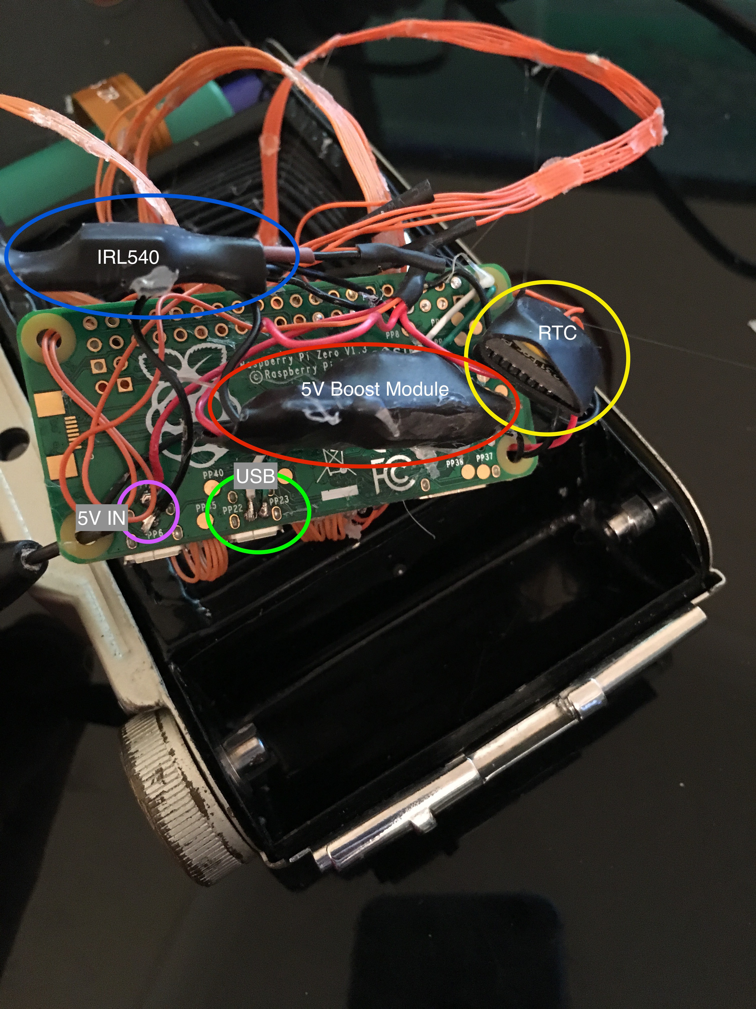
This tangle of wires comprises:
- IRL540 - This logic level MOSFET is able to switch a high current load, the flash, using a low current GPIO pin's output. This particular component is probably a bit overkill for what I ended up needing but better too good than not good enough. Plus I'd already soldered it.
- 5V IN - PP6 and PP1 are used to supply 5V to the board direct from the 5V boost module. No room for a micro USB plug.
- USB - PP22 and PP23 are used to tap into the USB data lines. These are taken to the other side of the board and connected to the WiFi/Bluetooth module
- 5V Boost Module - As mentioned above, takes the input from the LiPo cell which can be anywhere between 4.2v and around 3v and boosts it to the 5v required for the Pi.
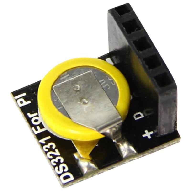
- RTC - Real Time Clock. The Pi does not have any on board battery so cannot maintain the correct time while powered off. This can be set via NTP over the internet but as I won't have net access I'm using an RTC which communicates by I2C so is connected to the I2C pins on the Pi
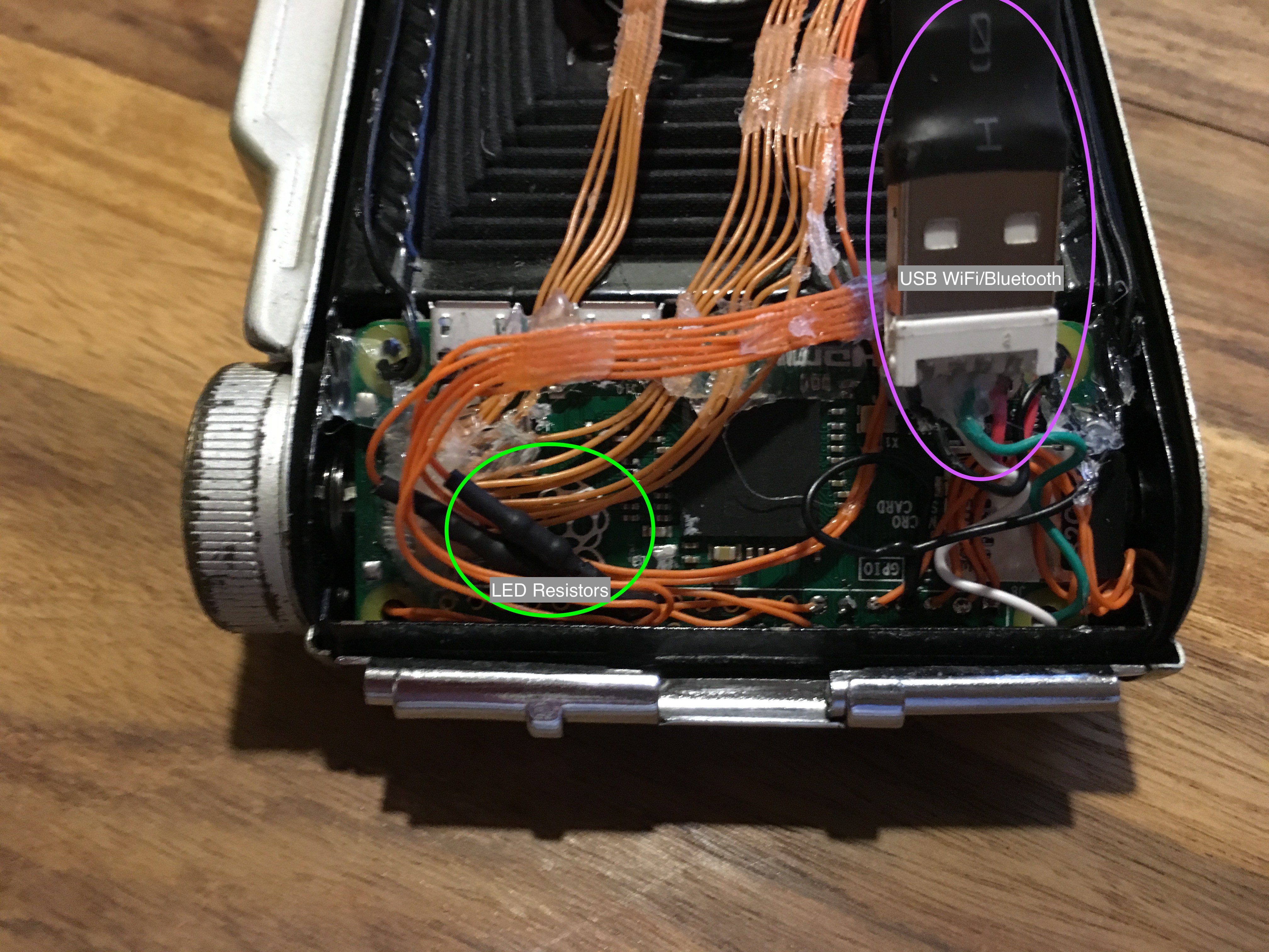
These all bundle up and fit in the recess with the board on top
![]()
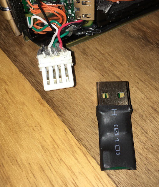
The above pictured shows the Pi wedged in the film compartment with the 5V booster, MOSFET and RTC hidden from view underneath. On this side we can see the current limiting resistors for the indicator LEDs along with the WiFi and Bluetooth USB dongle. As the USB port is wired directly to the Pi's SoC and not through a hub, we only have one port available. Therefore, without the space for a hub I needed a combined WiFi + Bluetooth adapter. There aren't many available but i went for this one and stripped it of its case.
![]()
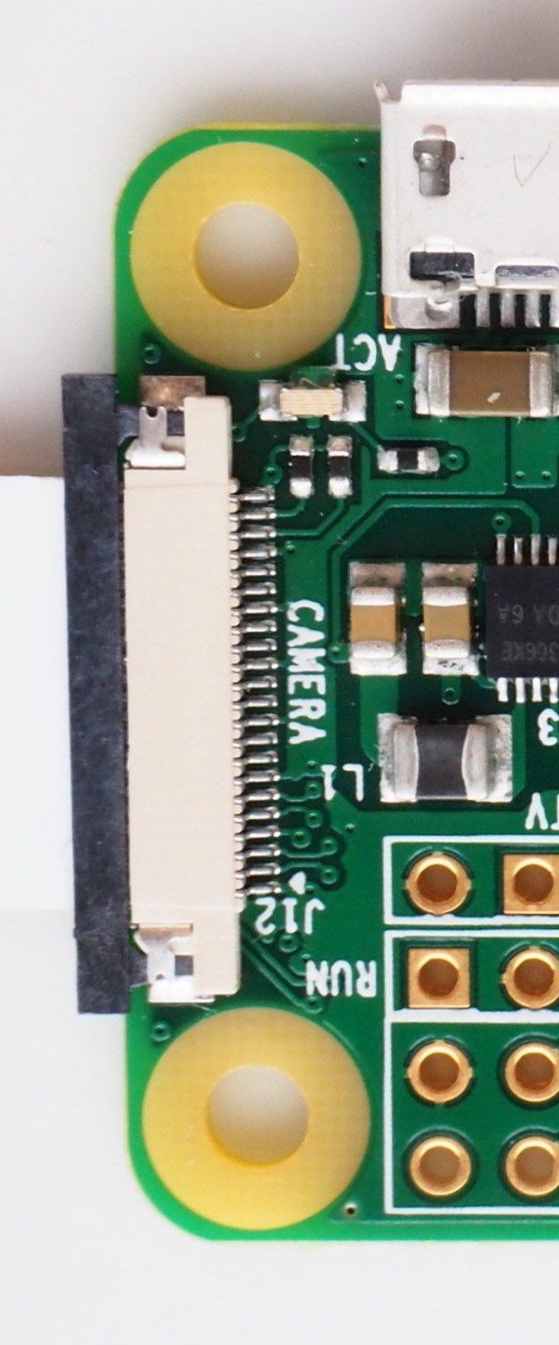
The Pi Zero Camera Connector
Given the space constraints and the location of the connector, I could not use a ribbon cable to connect the camera module to the Pi Zero. When I tried, I had to bend the cable so much that it stopped working.
![]()
The minuscule connector above is on the opposite end of the board to the SD card which meant I couldn't cram a ribbon cable in to it. The solution? Remove the connector and solder wires directly to the connector pads!
![]()
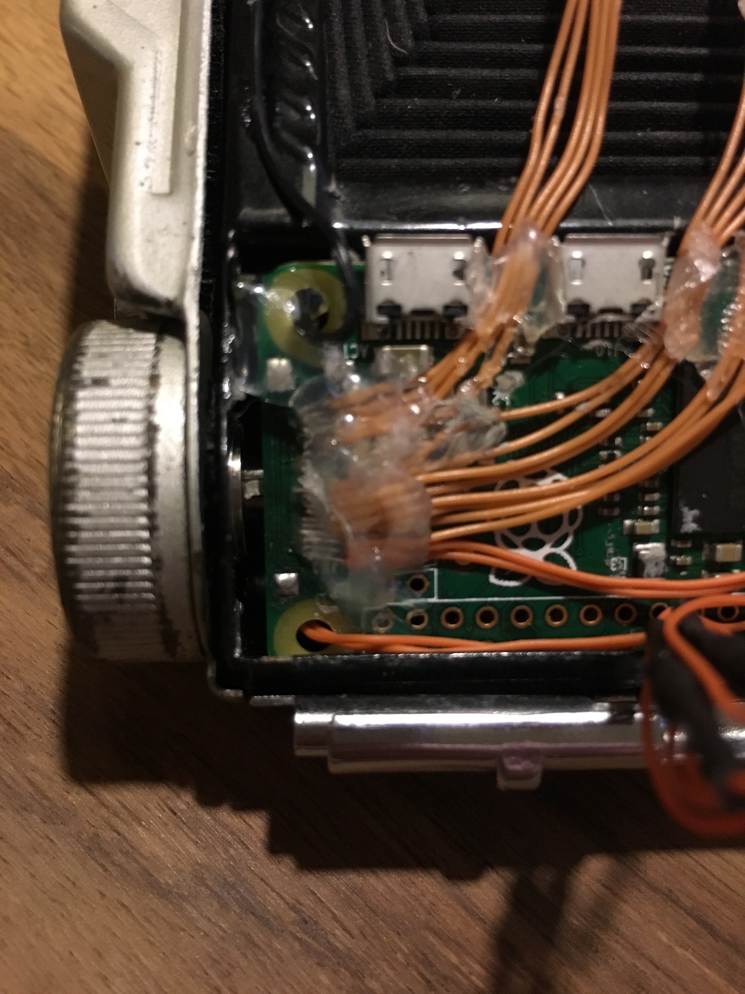
The connector pins are such fine pitch I thought I'd have no chance of it working first try. Happily I was wrong and the camera sprung to life on the first power on! A good dollop of hot glue to immobilise the connection and all was well. Or so I thought.
During testing/development of the software side of things, about half of the photos taken would have 'artefacts'. Half the photo green or purple, 'static' horizontal lines etc. I had a suspicion this was down to crosstalk as I had just arranged the cables in one big bunch rather than in the same order they are on the ribbon connector. Thanks to Peter Vis and his CSI pinout list, I was able to identify the important channels and bunch them together in improvised ribbon cables (hot glue - yay!).
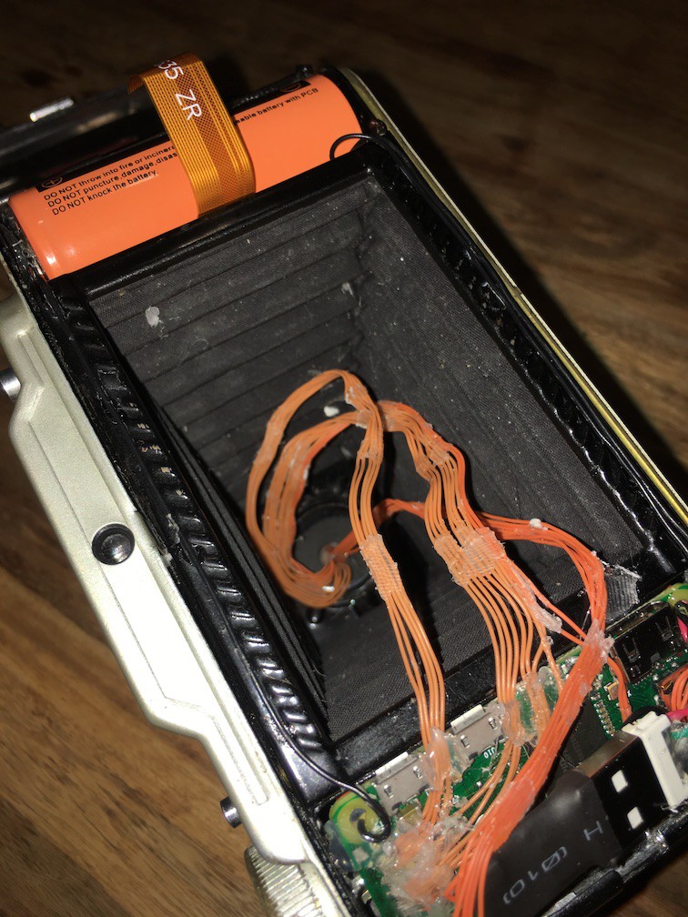
![]()
These are arranged as they are in a kind of spiral to allow for expansion when the bellows are opened.
![]()
And finally, video of it in action (sorry about the vertical video, I'll do better next time).
![]()
![]()
-
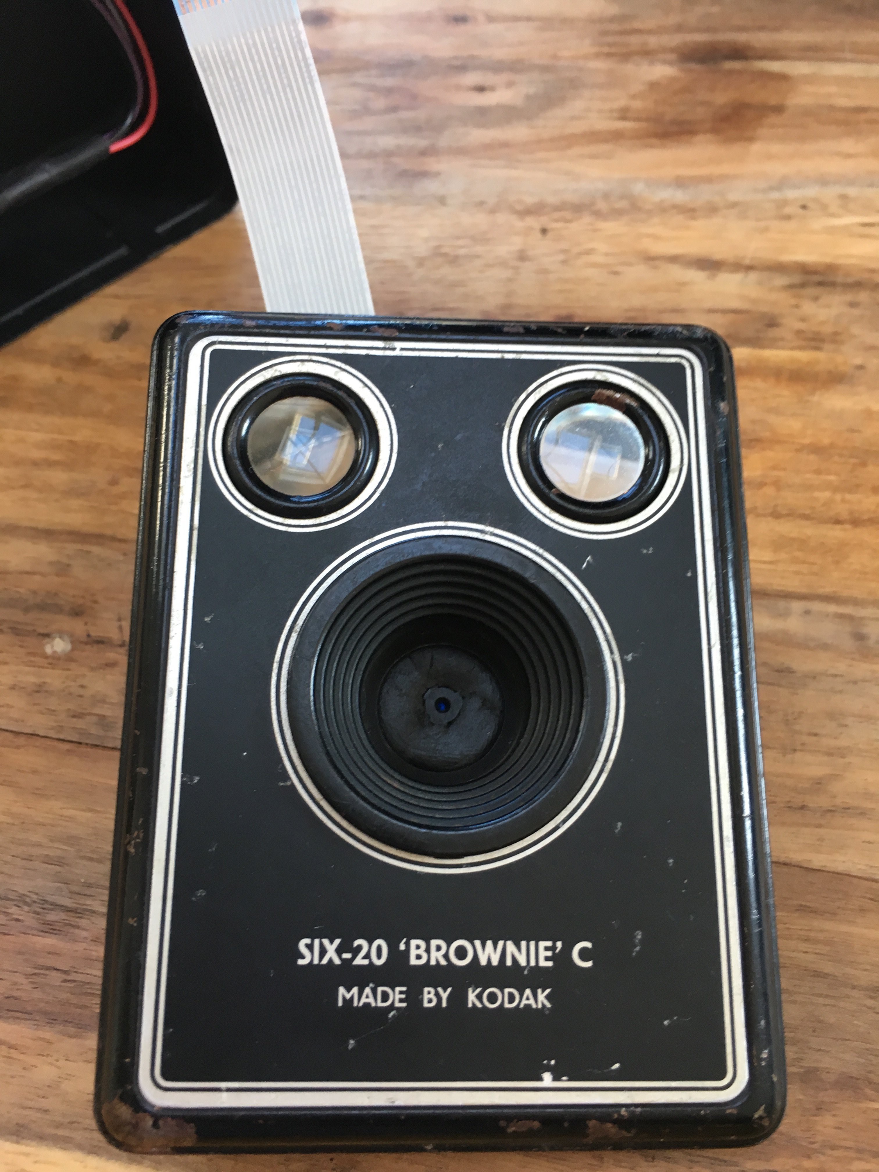
Box Brownie - Pi A+
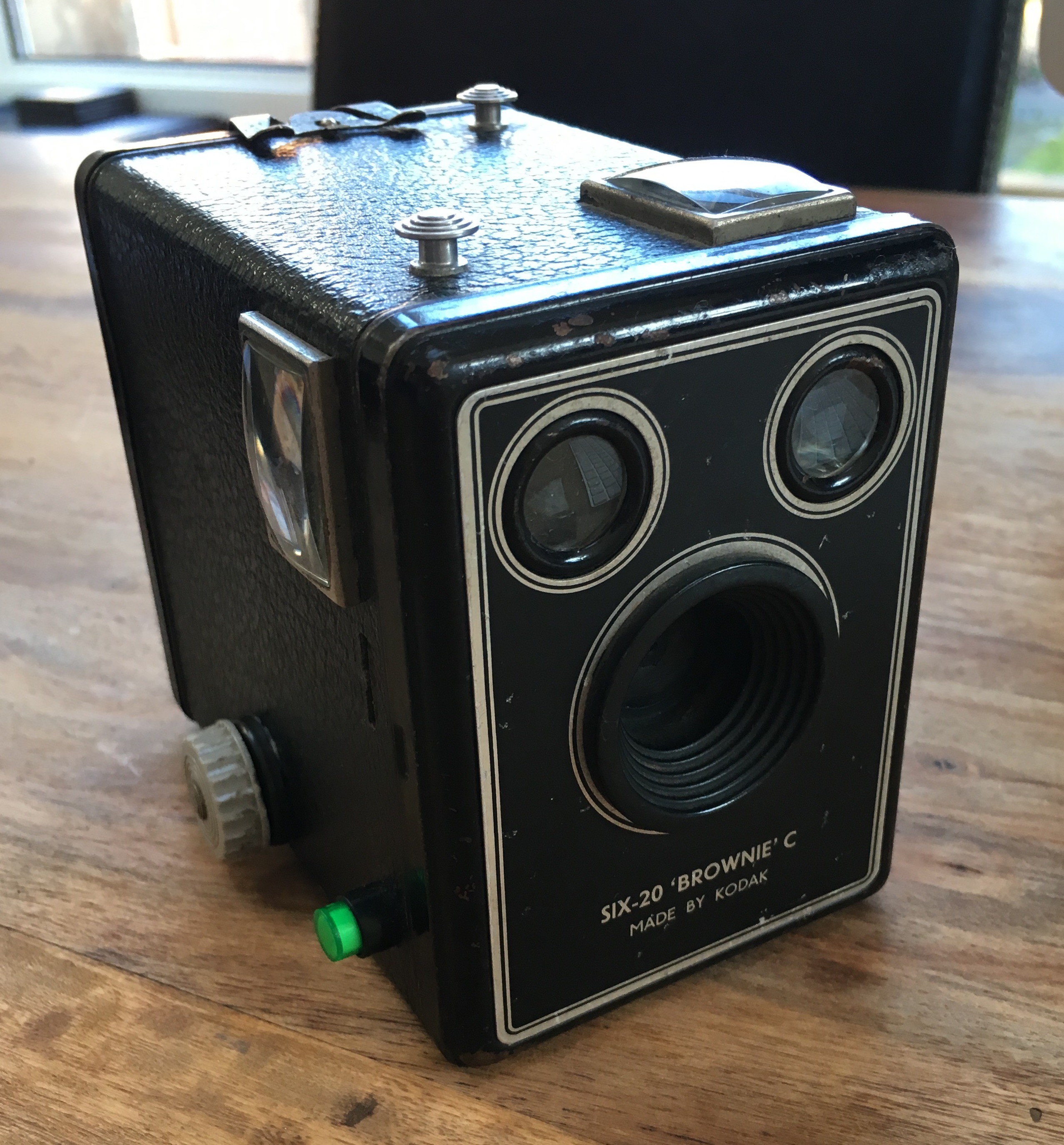
01/20/2017 at 15:03 • 0 commentsThe finished camera looks like this
![]()
As you can see it looks pretty much unchanged aside from the manual shutter release has been replaced by a green ed momentary switch. The closest part I can find now is http://uk.rs-online.com/web/p/push-button-switches/8207533/. This has 4 connections
- LED -ve and +ve
- Switch -ve and +ve
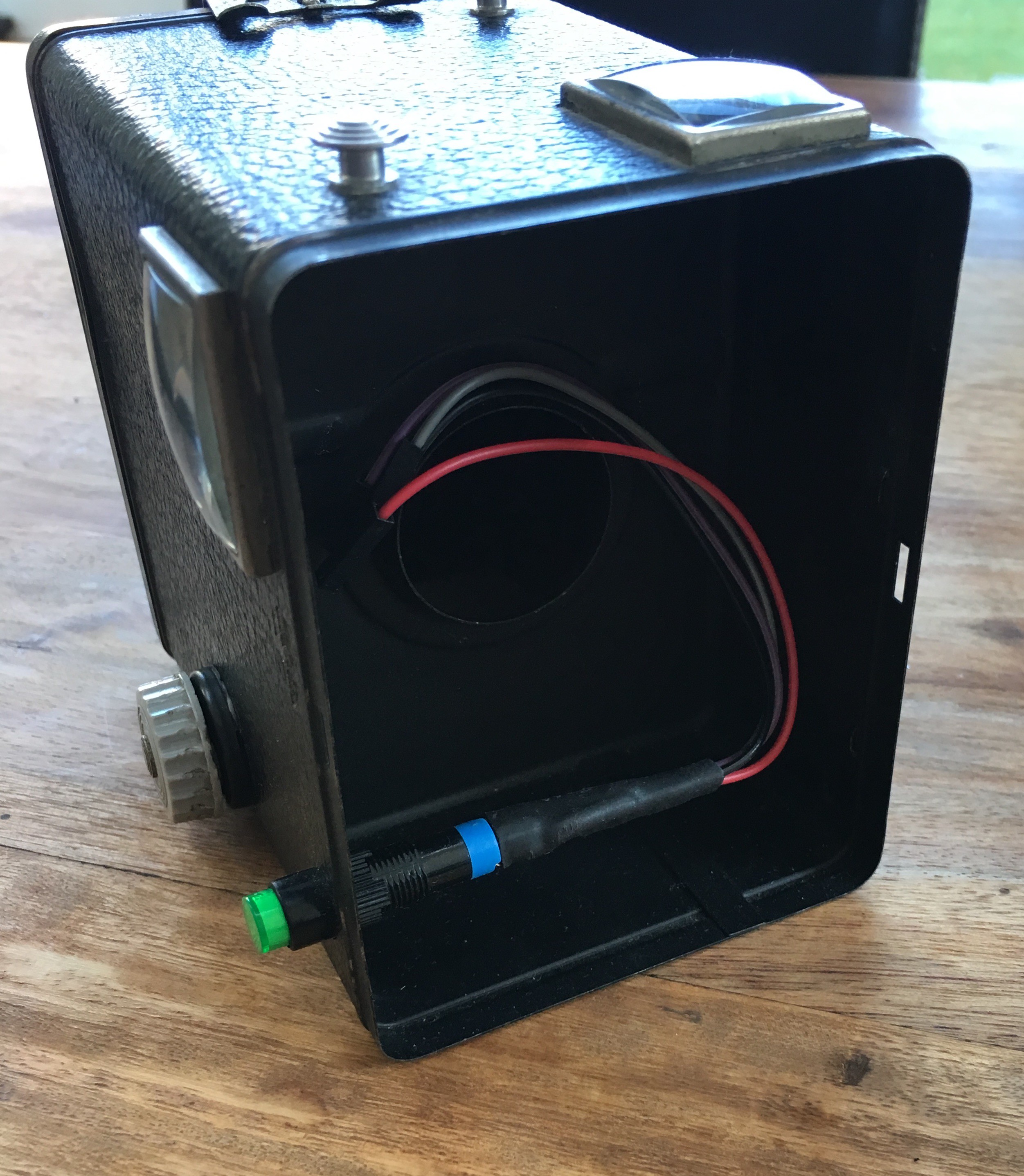
The original lens was removed from the front plate and the Pi camera module mounted using black Sugru![]()
![]()
The camera ribbon cable and the 4 button connections are then fed through the aperture and connected to the A+![]()
![]()
You can also just see the USB Wifi adapter in the port of the Pi. not pictured is a Real Time Clock module as this has been reused. This was needed as without net access to set the time via NTP, the timestamp on the photos would be wrong. This connected via I2C and didn't take up much room.
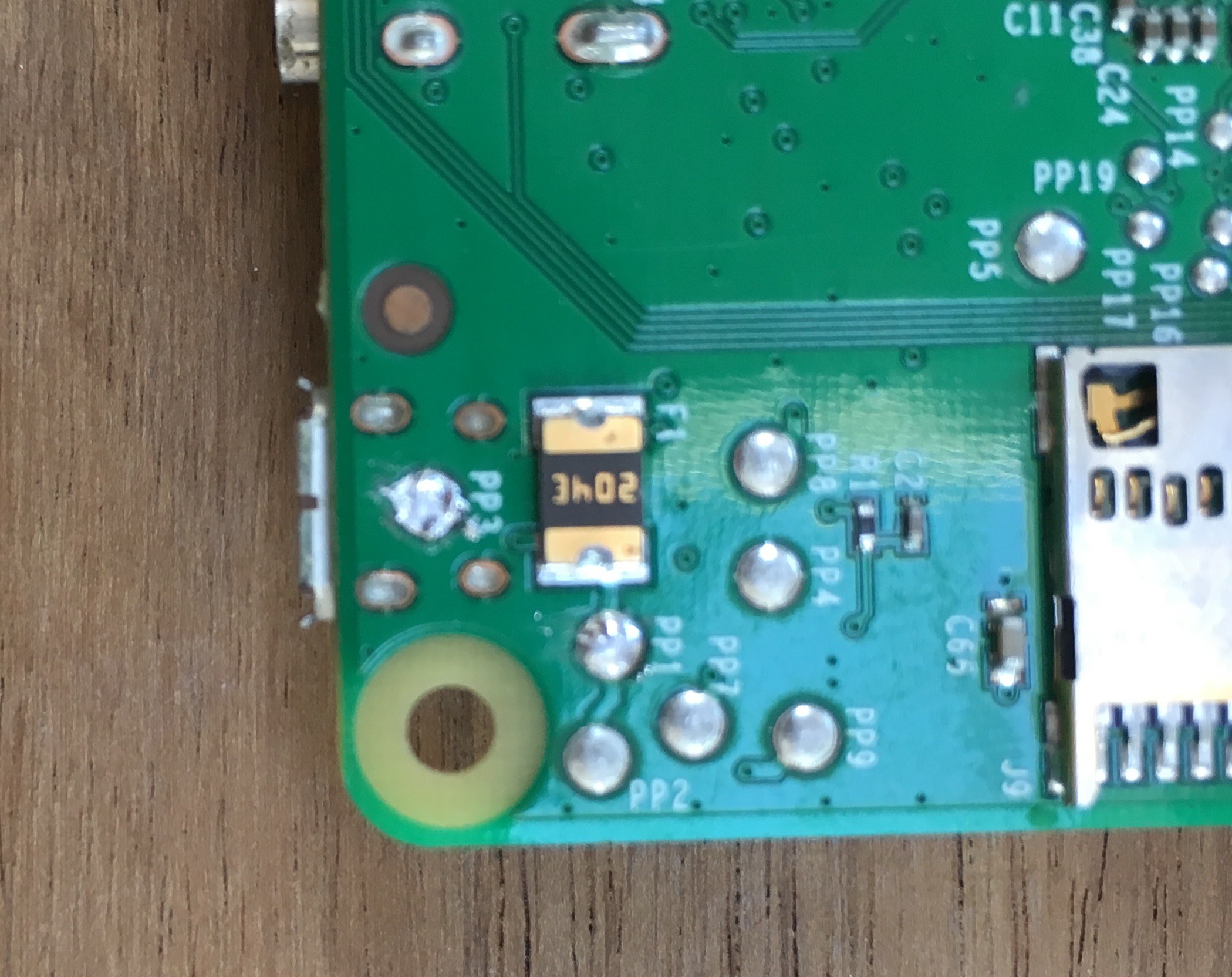
The Pi was powered by a USB power bank that sat in the space on the right. As the case was not big enough to allow a microUSB cable to be plugged in to the Pi, I cut up an old USB cable and soldered on to the PP1 (+5v) and PP3 (GND) test pads on the underside of the board![]()
![]()
**I last looked at the code for this a couple of years ago and the below is written from memory, so may contain slight inaccuracies**
For the software side of things, I built a custom linux image based off buildroot and motioneye which booted up and ran a python script to give the camera the following features:
- Flash the shutter button until the camera is ready to take a photo (using RPi.GPIO python module)
- Take a photo with press of the shutter button (PiCamera python library).
- Use the Wifi adapter to host an access point. When clients (smartphone) connects, dnsmasq assigns an IP via DHCP and responds to all DNS requests with the IP of the camera. This is similar to a captive Wifi network at an Airport/Coffee Shop etc. that requires sign in.
- Serve a web interface with a live view of the camera via mjpeg along with a shutter button and a link to a gallery of photos stored on the camera (bits of code borrowed from http://elinux.org/RPi-Cam-Web-Interface). This was optimised for smartphone access.
- Put the camera to sleep with a long press and release of the shutter button. This would turn off the Wifi and camera and wait for another long press of the button to power back up.
This worked well but had a few drawbacks:
- No flash.
- No physical photo.
- 'Sleep' mode was actually quite power hungry
- The live preview was kind of useful for framing the shot but distracting when using it to take group selfies - most of the shots would have me looking at my phone to press the shutter button rather than at the camera.
These features will be addressed in the next version of the camera.
Wishlist:
- More interesting camera body (just a box is a bit boring)
- Auto flash
- Physical photo option
- Remote trigger (selfie button - RF, Bluetooth, Wifi, IR etc.)
- More elegant power on/off. Battery life was OK, but could be better. Full power off is made difficult as halt/poweroff/shutdown commands do not fully power down the Pi, it needs to be physically disconnected.
Adventures in Digitising Vintage Cameras
Take an unloved old camera and give a new lease of life
 The cutting/shaping of the black plastic isn't as neat as I'd like, but it does the job. The blue LED is lit when the Pi has power (it runs of the constant 3.3v from the GPIO connector) and the green LED lights when the camera is ready (it is connected to a GPIO pin that is controlled in the python script)