 Quinn
QuinnNothing super complicated in disassembly, but adding a lot of pictures for reference in reassembly.
Overall it's really well constructed for serviceability which is great. There are a couple nuisances like the handful of wires which are directly soldered, instead of using connectors, that have to be removed to remove the board/module. They are well labeled though.
The service manual does a good explanation of the basic opening, as well as exploded parts view.


Many of the knobs were too tight to remove by hand. Not wanting to scratch them further, I used this trick using some old credit cards. These are not real credit cards, but rather the fake ones that are sometimes sent in the mail as advertising. Most of them now are cardboard, but they used to be all plastic. I just cut a few with a notch as shown, with the notch wide enough to go around the nut. First I put two under, then I slide a third (or more) between them. This forces the knob up from the bottom sides, without scratching the panel or knob. If you don't have any of these, and sort of firm think plastic like this should work.

I take note that there are two sizes of nuts. The larger are for the rotary switches.

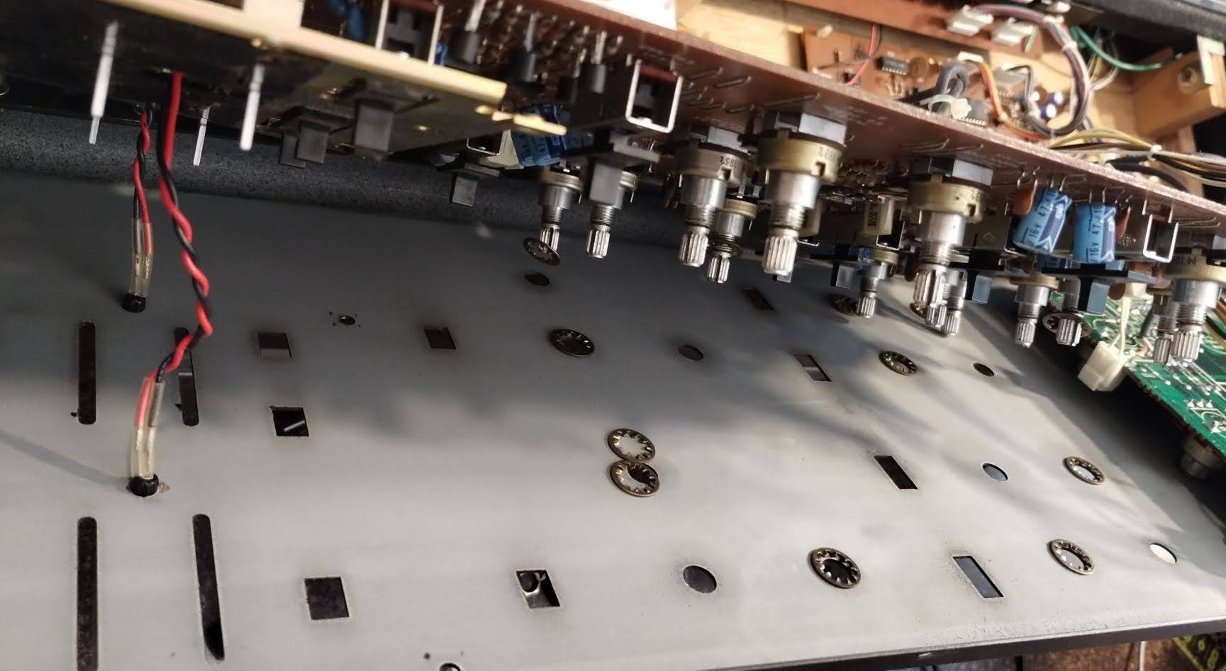
I found it surprising that they had placed lock washers between the pot on the inside and the inside of the panel. This of course meant they all fell off when removing the board. This does nothing towards keeping the nut secure. With some analysis, I think they are using them as spacers to make the rotary pots/switches match the height of the plate on top of the sliders.
A bunch of documentation pictures follow in case they are ever helpful in the future.
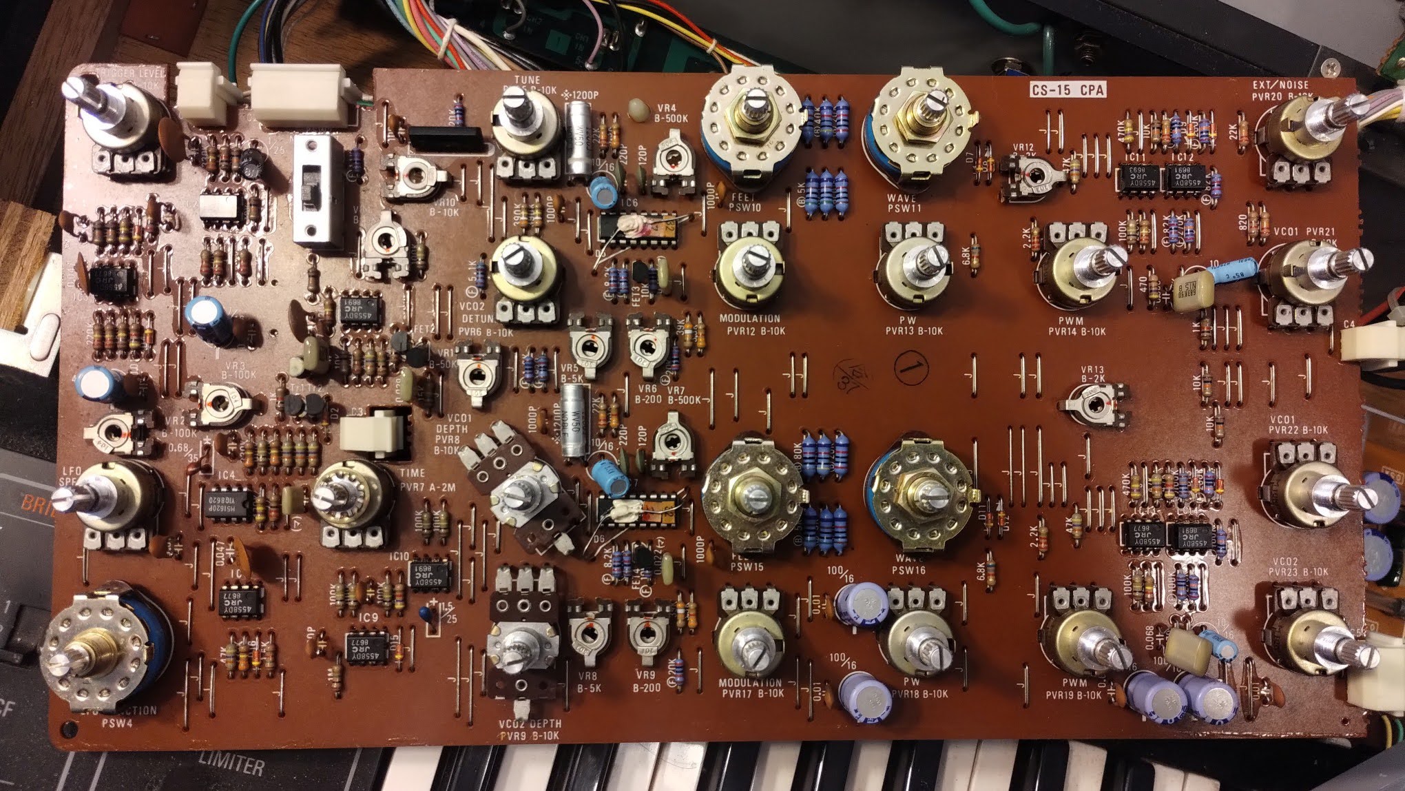
Details of the left board, CPA.
Top:


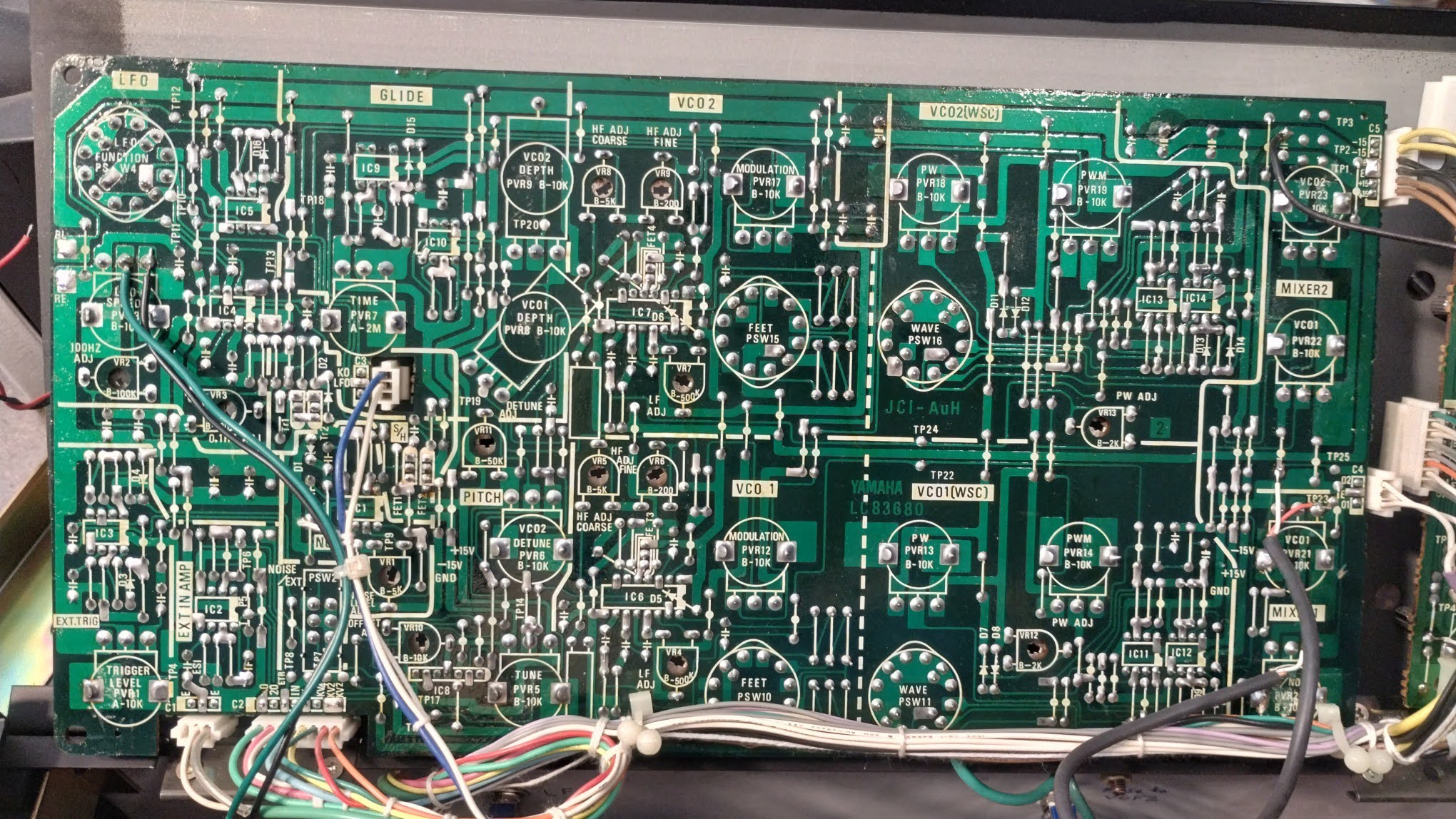
Bottom
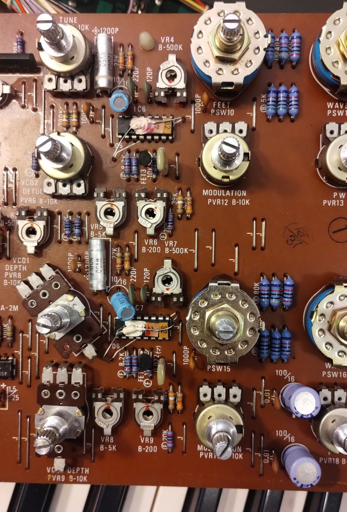
Detailed views, left to right
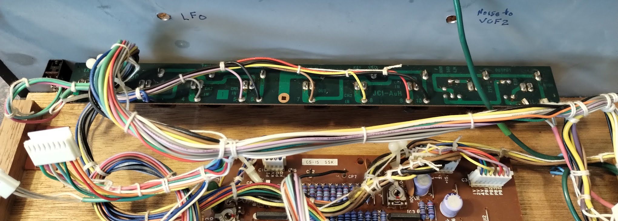
Below also shows the pads for the LFO LED, all the way on the left, labeled RE and BL. (It's been unsoldered at this point)


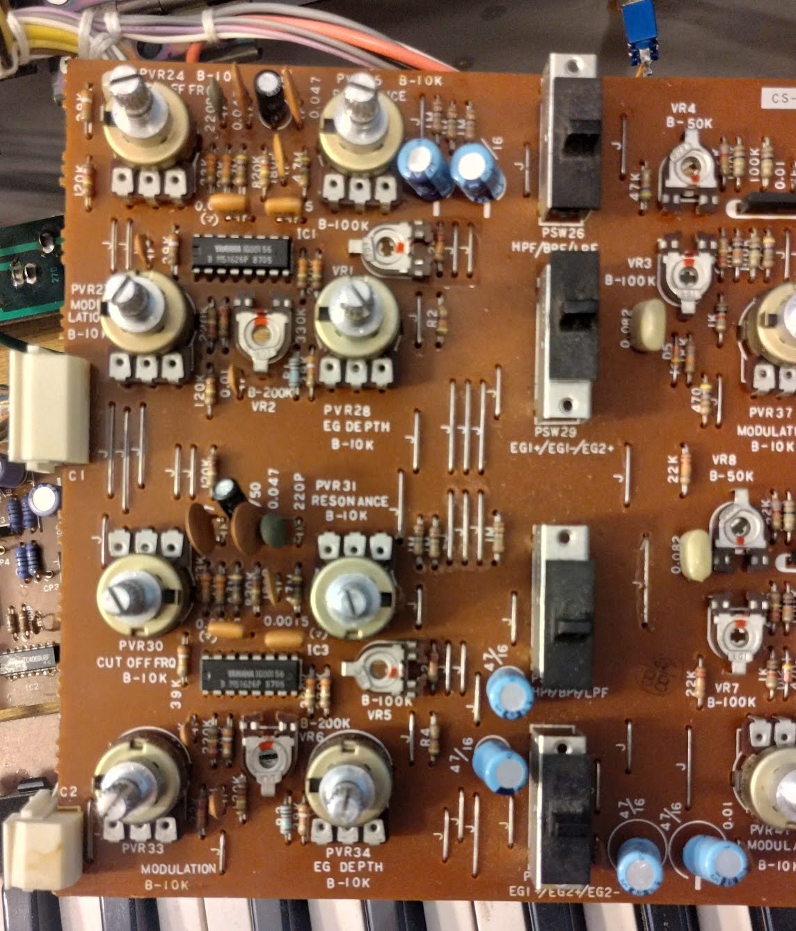
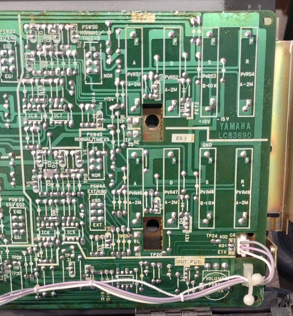
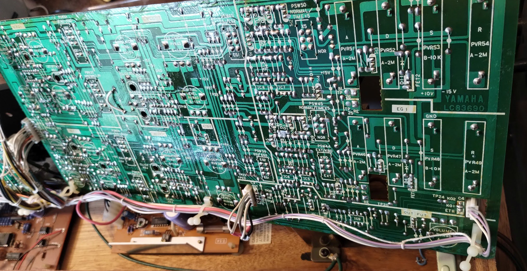
Details of the right board, CPB
Top

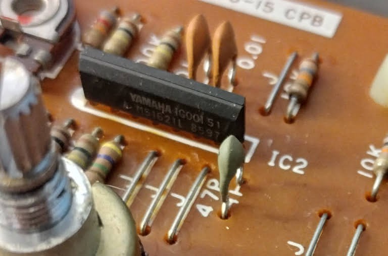
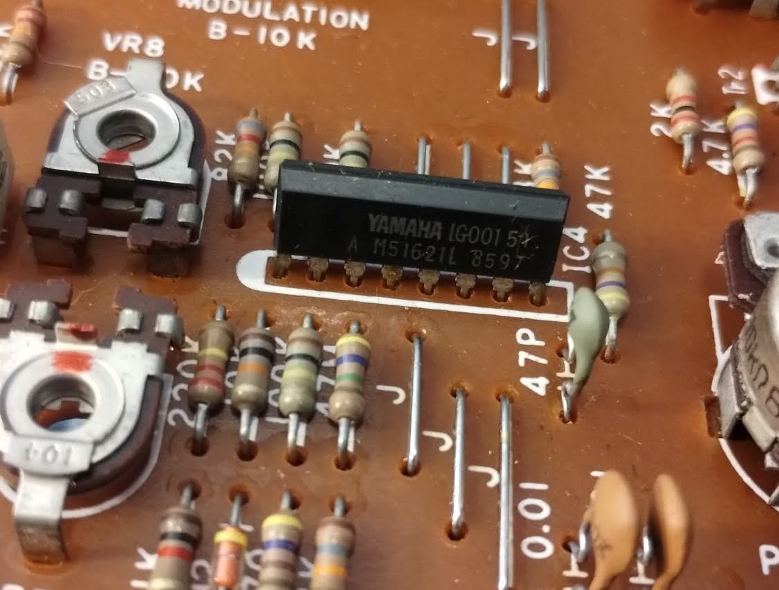
Detailed views, left to right


Bottom
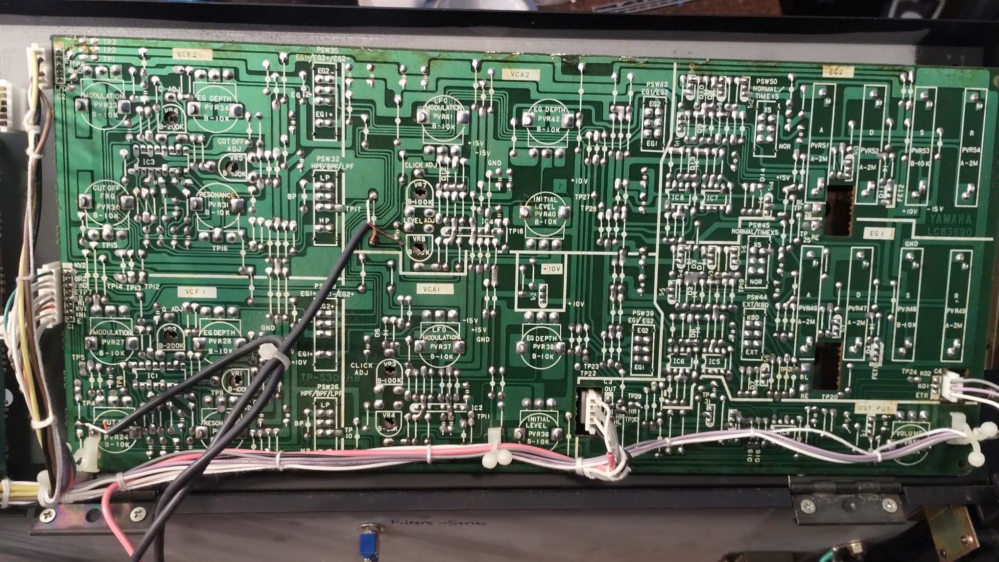
Detailed views, left to right
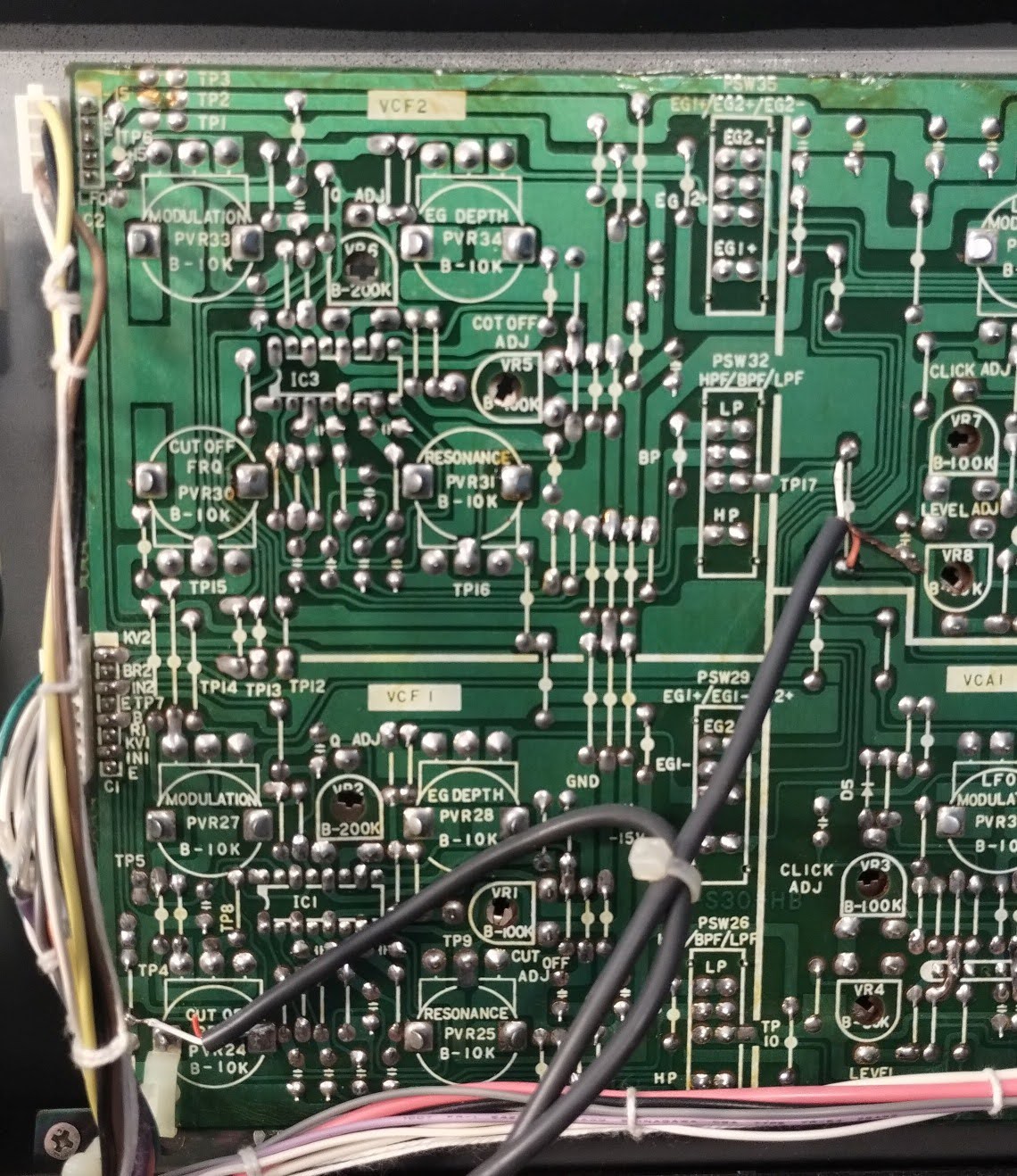

Below also shows the pads for the EG1 and EG2 LEDs, left of the openings, labeled RE and BL
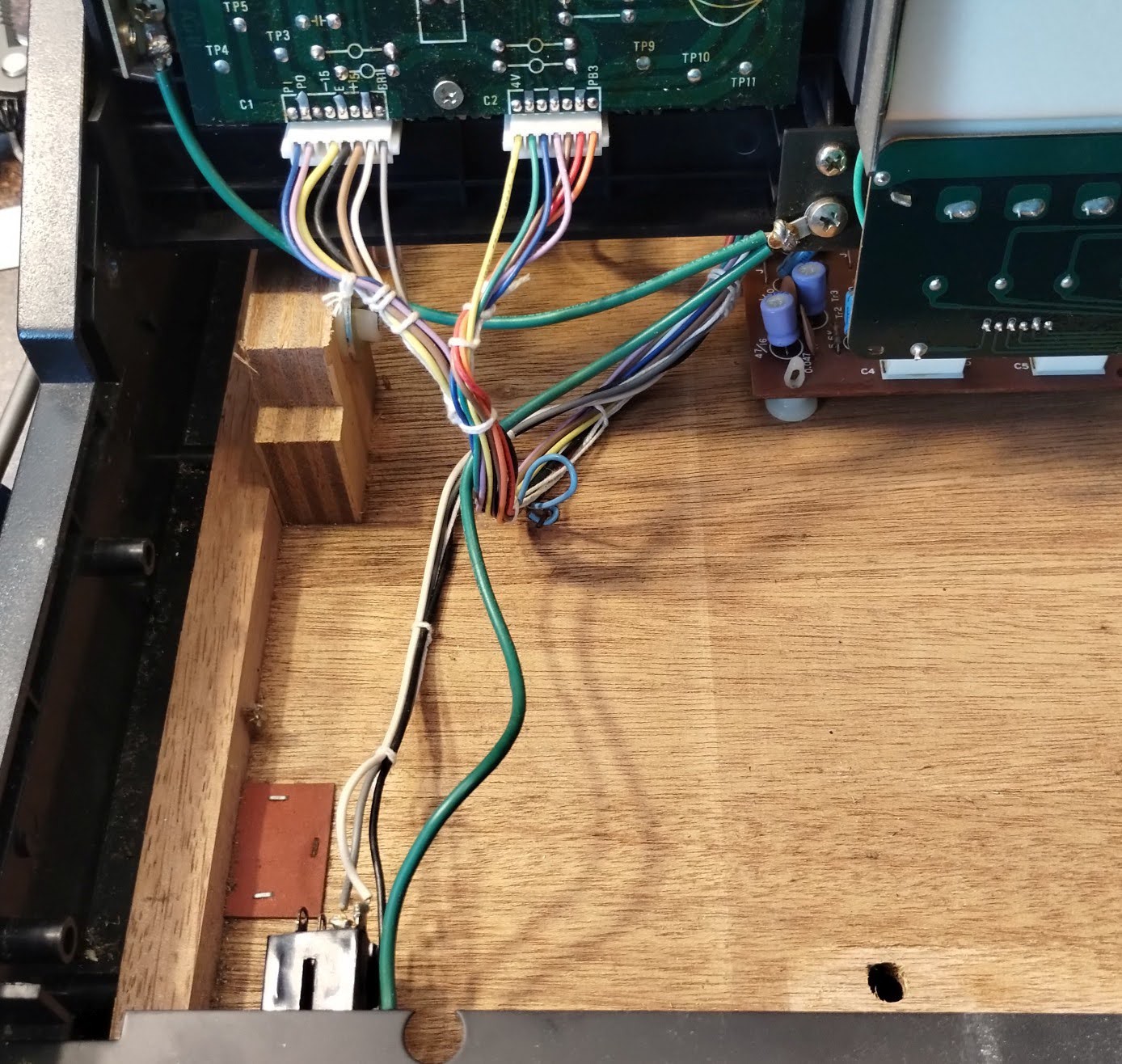
Details of wiring/connections
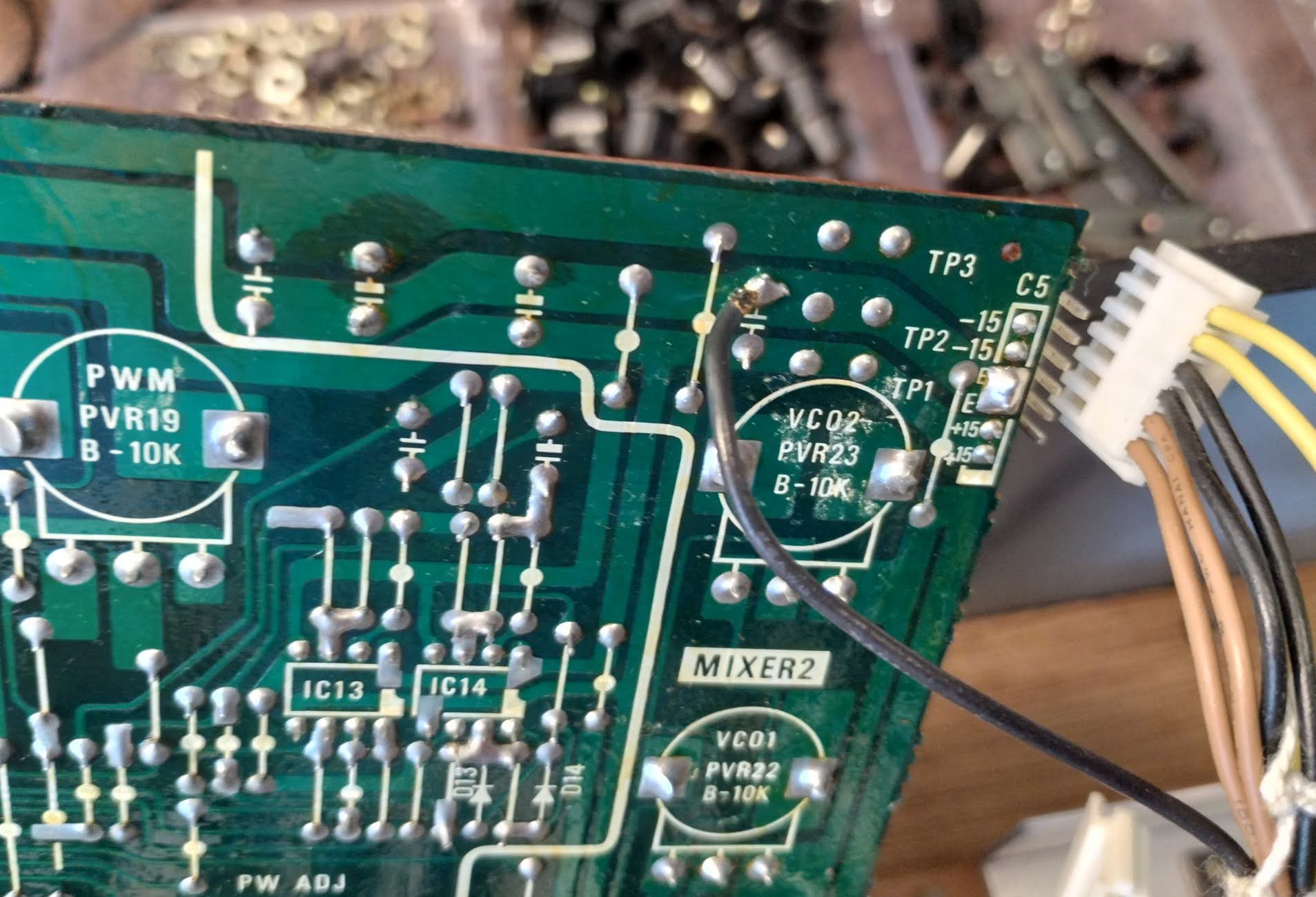
CPA


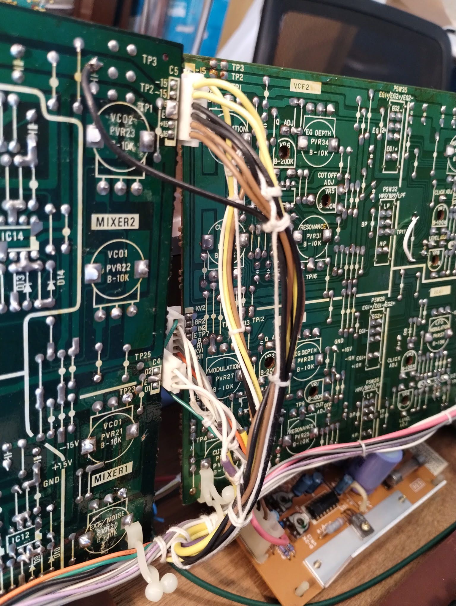
Heres one soldered wire, a ground. As it's in the loom, I suspect factory done. That they needed another ground and didn't want to use a larger connector
CPB


Keyboard


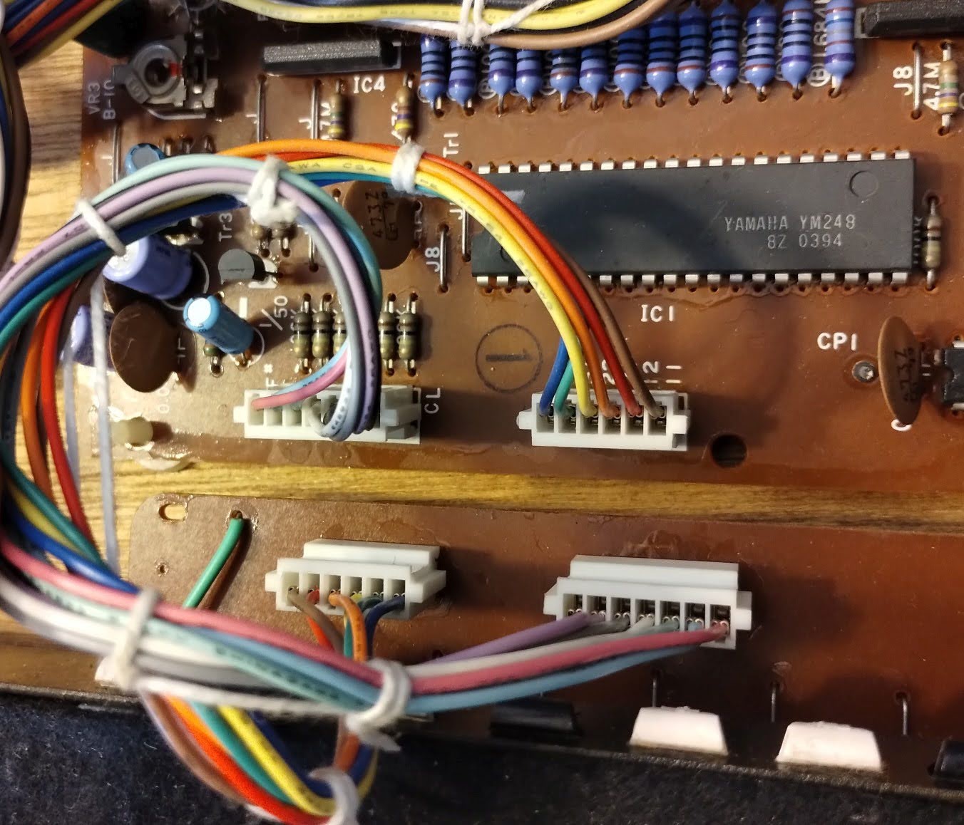
SSK

Here's another set of soldered wires, for the power LED

Rear panel

AC Inlet
The device in the middle below is identified in the service manual as a 2p terminal. (It's a 3p for the G/General export variant)

Discussions
Become a Hackaday.io Member
Create an account to leave a comment. Already have an account? Log In.