 Nguyen Vincent
To reduce ringing, I've added optional RC snubbers in the design. They are placed as close as possible to the FETs, but due to limited space, I was limited to using 0402 for Csnub and 0603 for Rsnub. This limits the maximum dissipated power in the snubber.
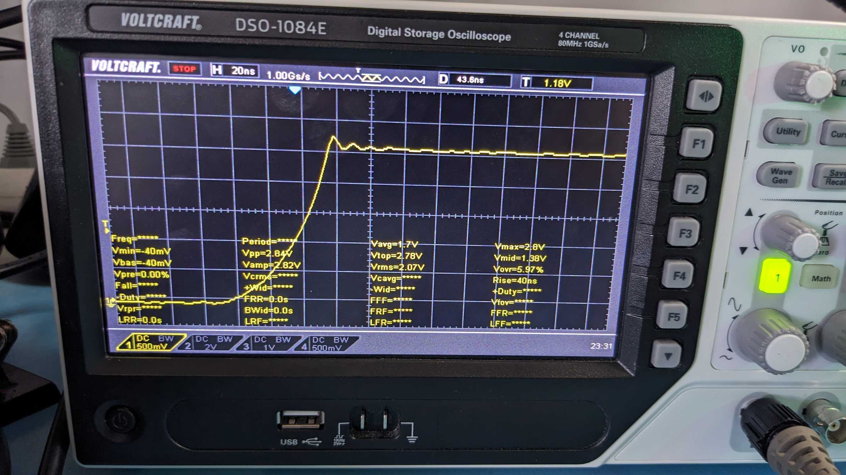
Before adding snubbers:
After adding snubbers:

I have decided to use 5 ohm 0.4W for the resistor, and 3300pF for the snubber capacitor. This proved to be a good balance between power dissipation and oscillation dampening. A good ressource for snubber tuning can be found here. The chosen passives result in an overshoot of around 4% compared to 8-10% before adding the snubber.
Currently, I estimated the dissipated power in the resistor using
Where α is a derating factor between 0 and 1, usually around 0.43 (see Correct Snubber Power Loss Estimate Saves the Day). With a frequency of 30kHz at 44V with α = 1, this results in a power dissipation of 0.19W.
When measuring high-frequency signals such as this one, it is important to use a probe with the lowest amount of inductance (i.e. with a short ground clip). As I didn't have such a probe on hand, I had to improvise something:
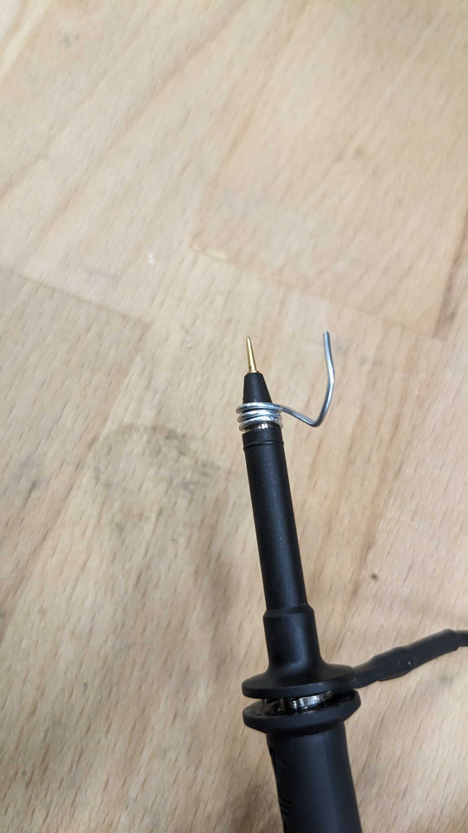
This significantly improved the maximum bandwidth that could be measured. However, it would be a good idea to redo the measurements with a faster oscilloscope.
With standard ground clip:
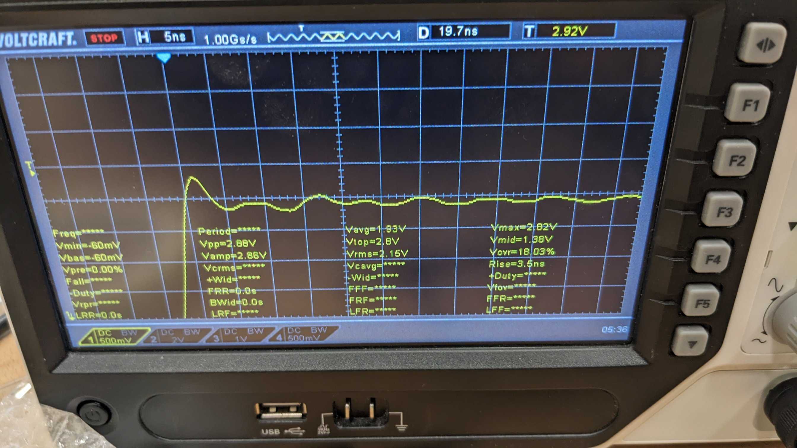
With handmade ground clip:

Discussions
Become a Hackaday.io Member
Create an account to leave a comment. Already have an account? Log In.