This project is currently on an indefinite break. We hope it can help with your endeavors!
0%
0%
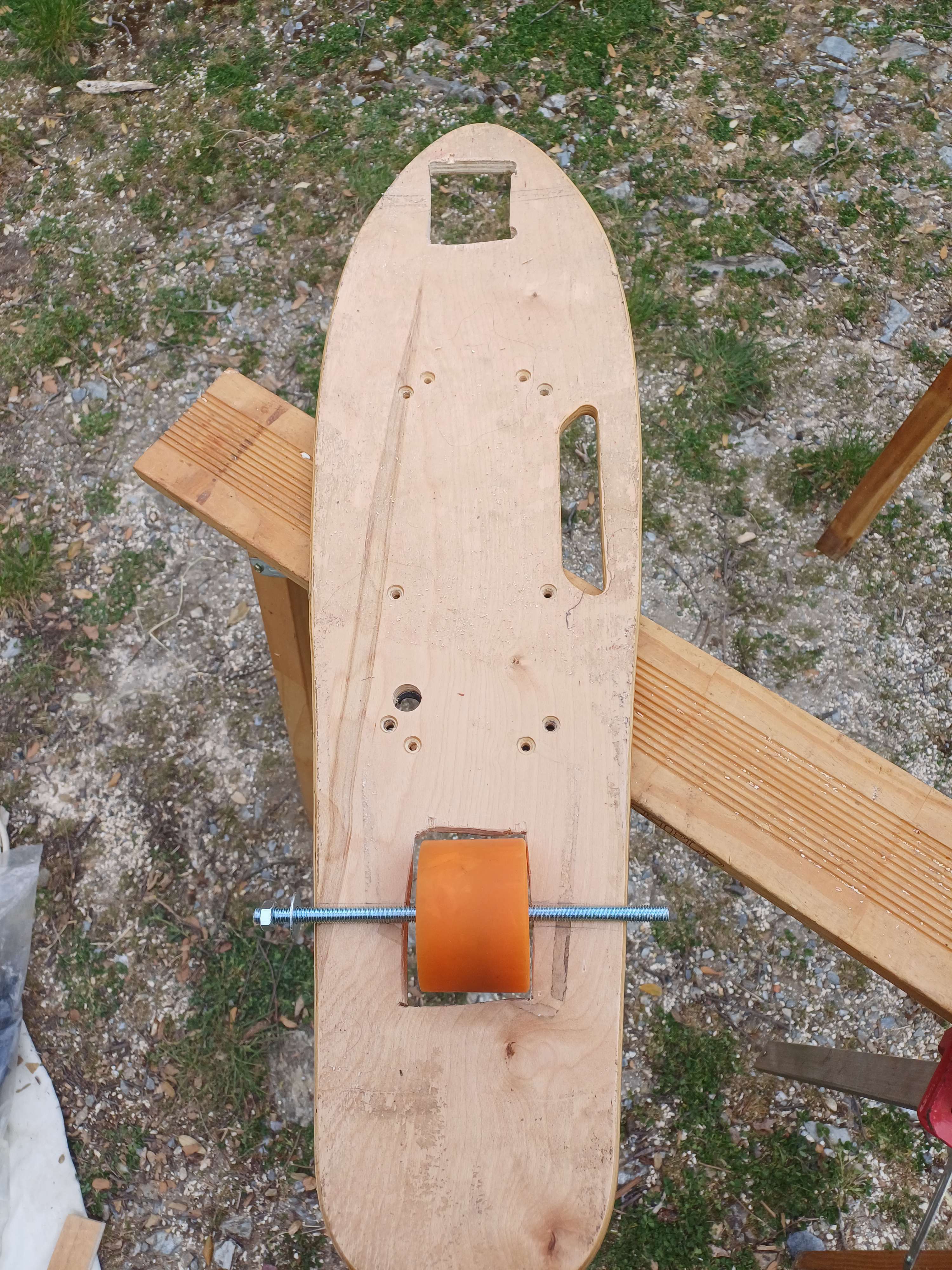
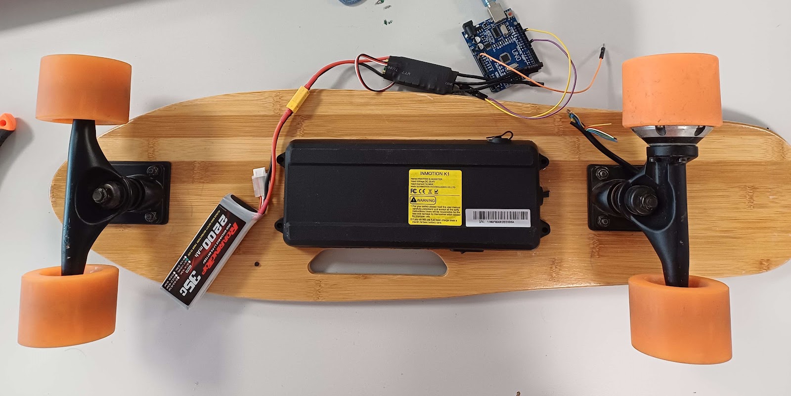
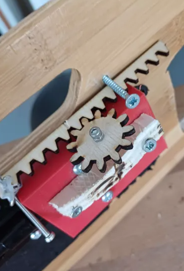
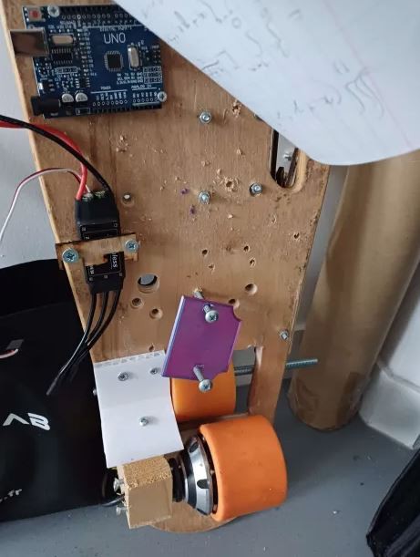
Dangerous Skate
The goal is to create a skate moving erratically
Become a Hackaday.io member
Already have an account? Log in.
Just one more thing
To make the experience fit your profile, pick a username and tell us what interests you.
Pick an awesome username
hackaday.io/
Your profile's URL: hackaday.io/username. Max 25 alphanumeric characters.
Pick a few interests
Projects that share your interests
People that share your interests

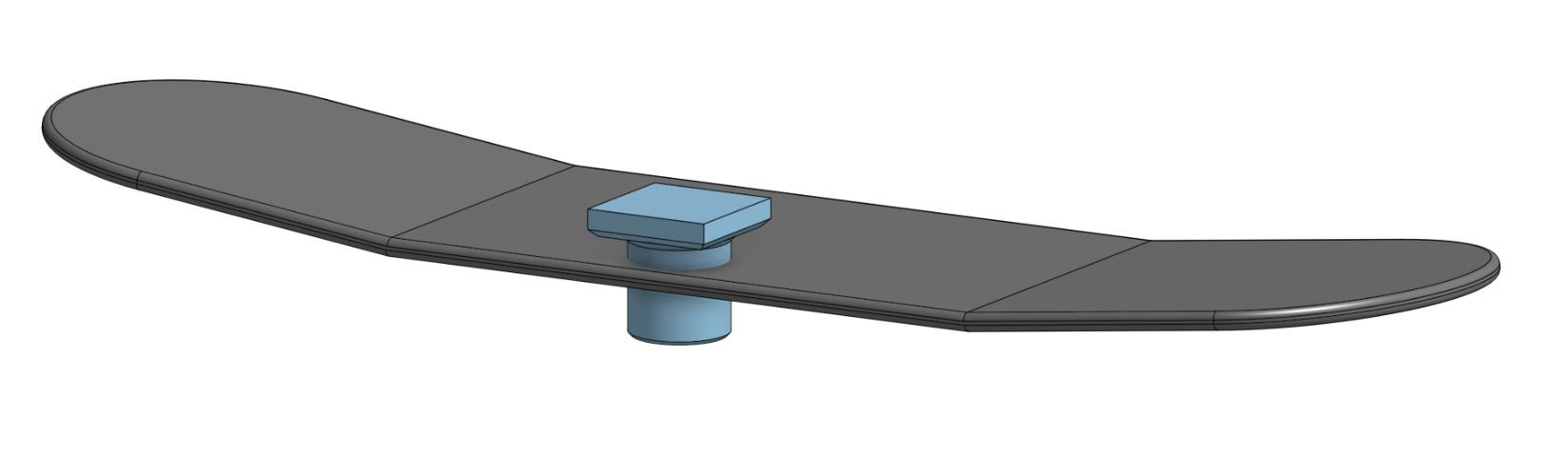
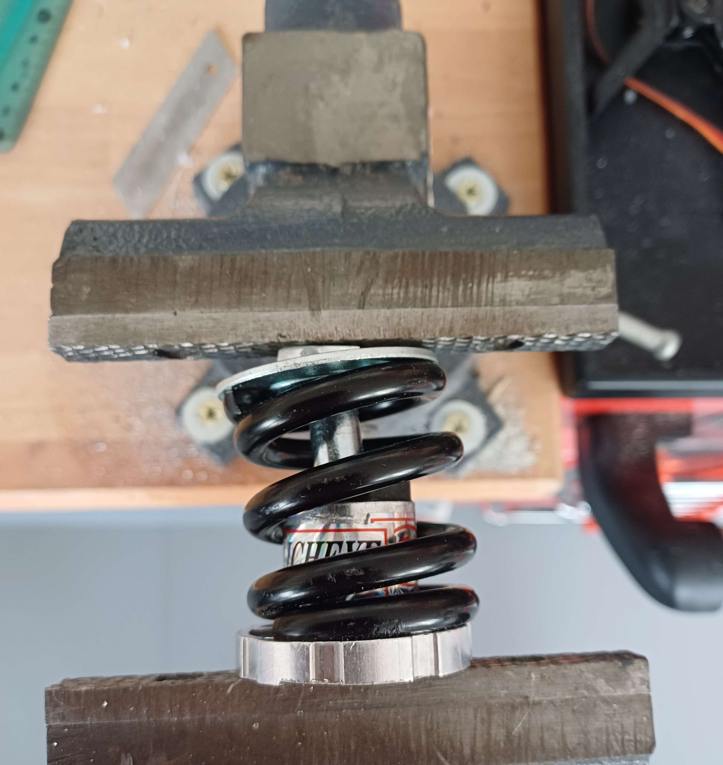

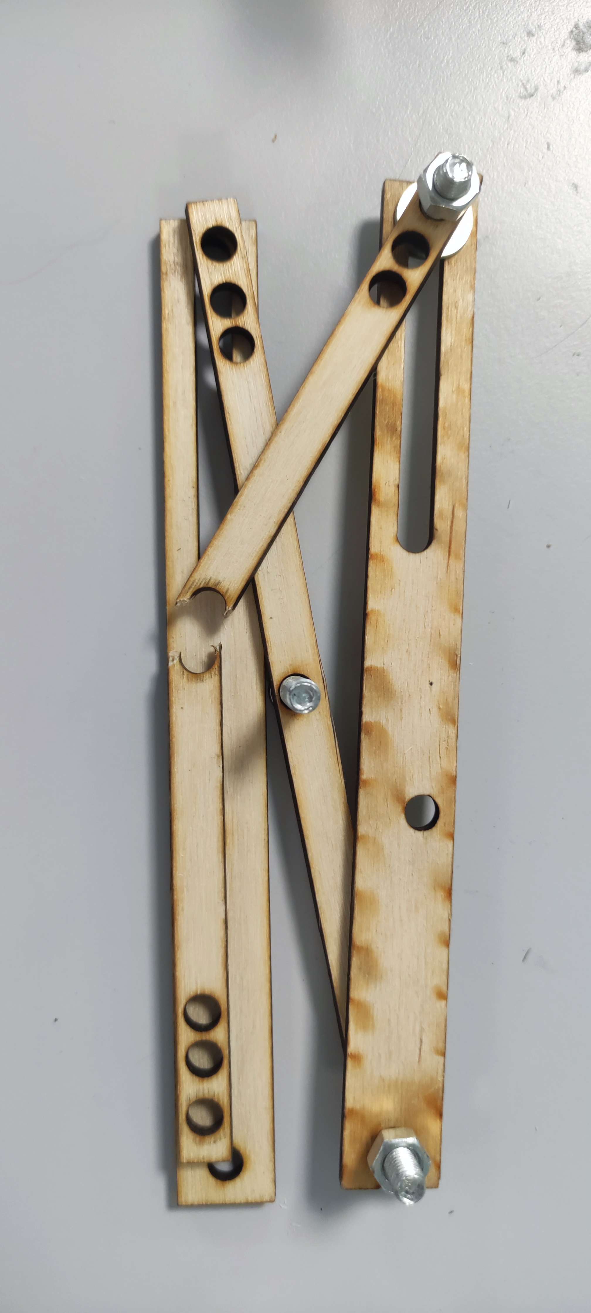


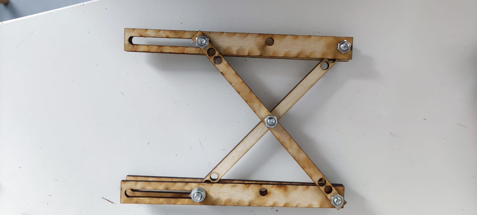
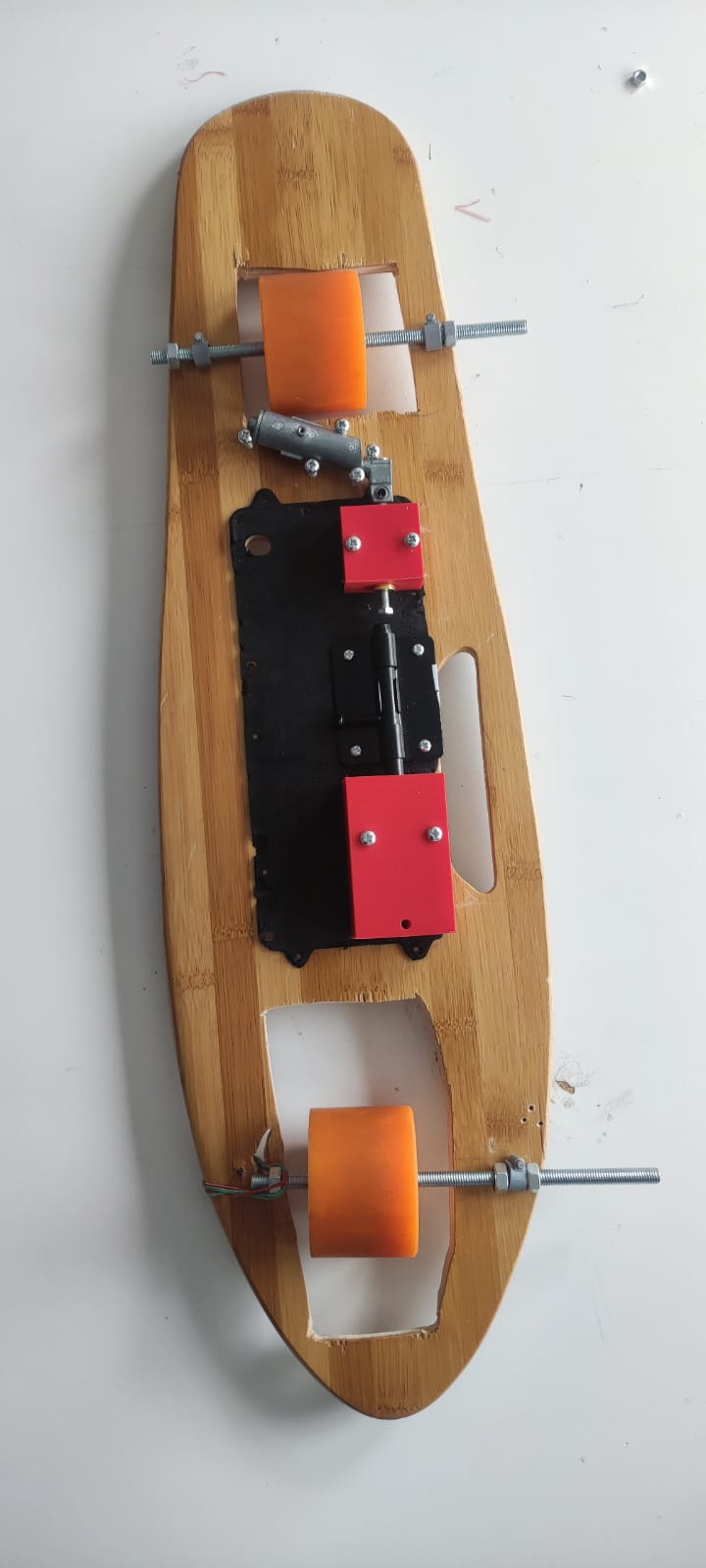


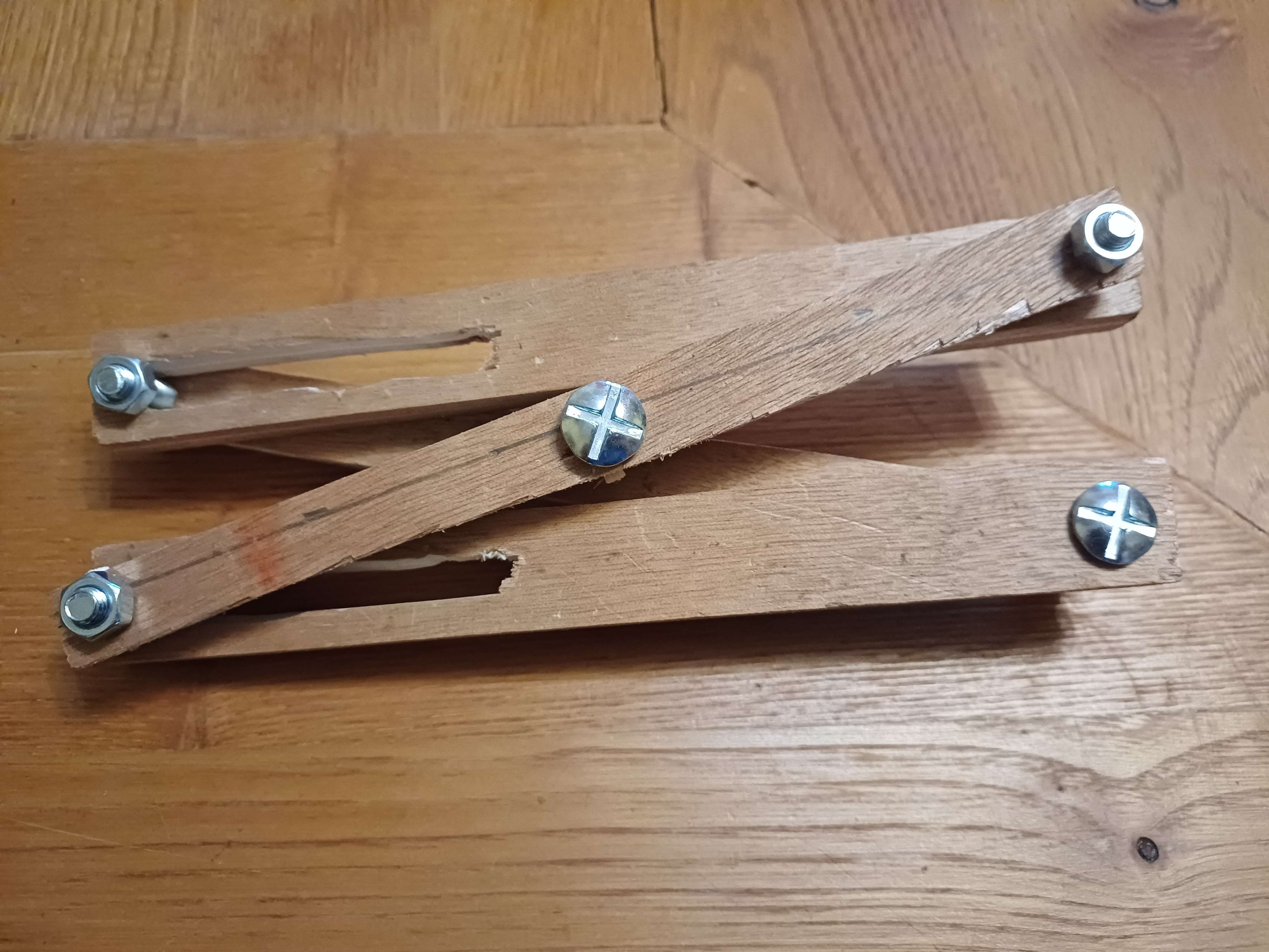
 Up-up view
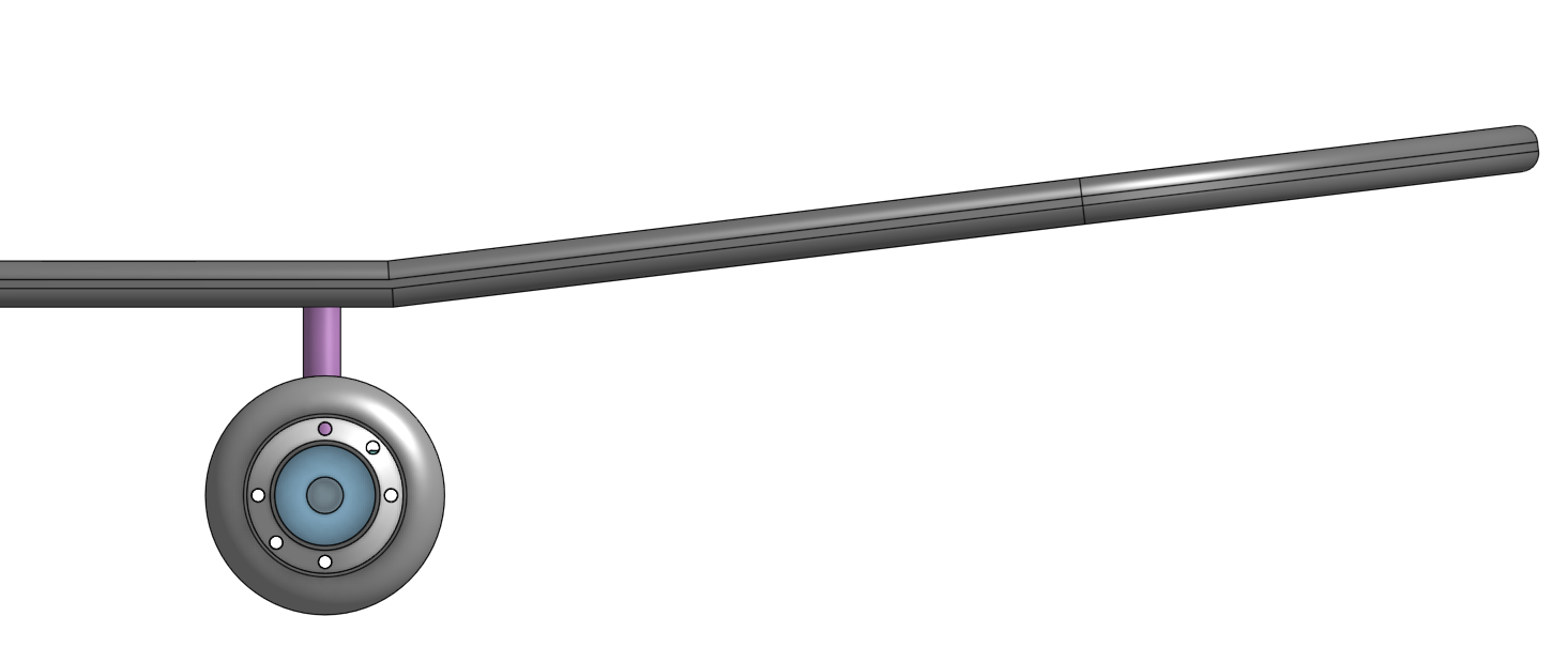
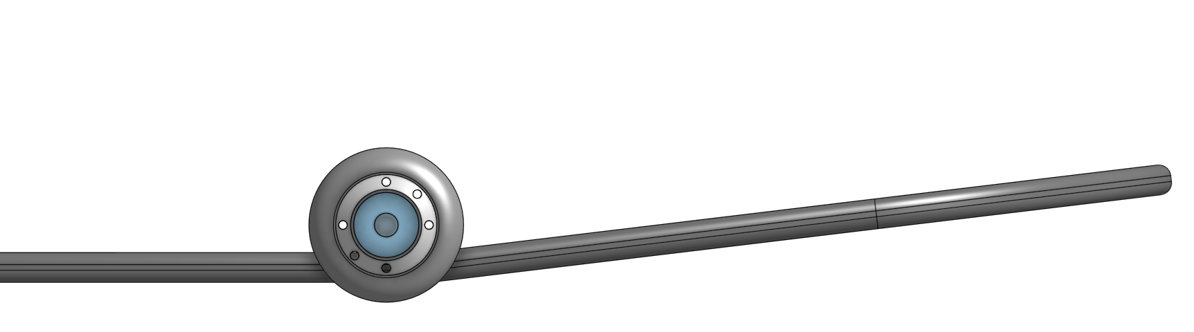

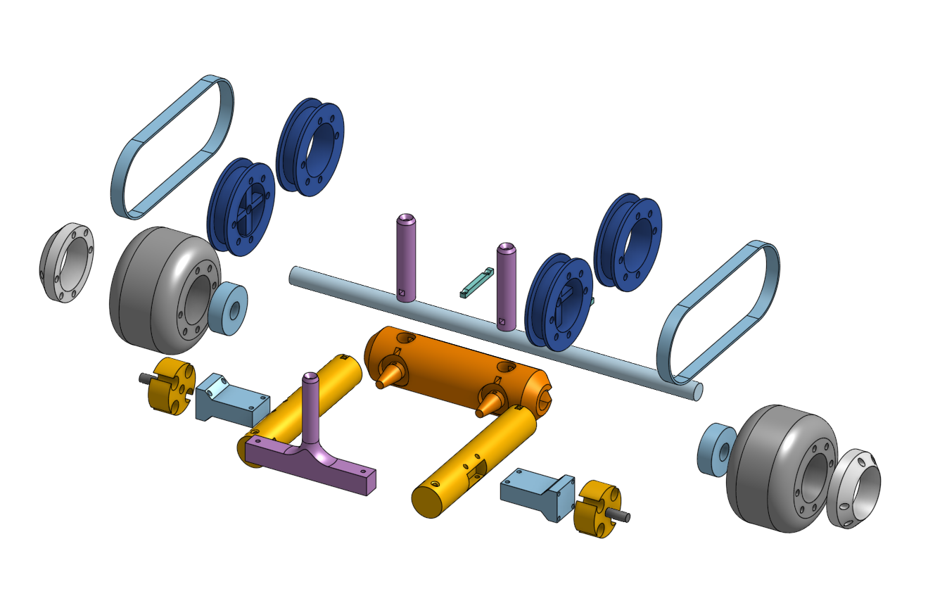
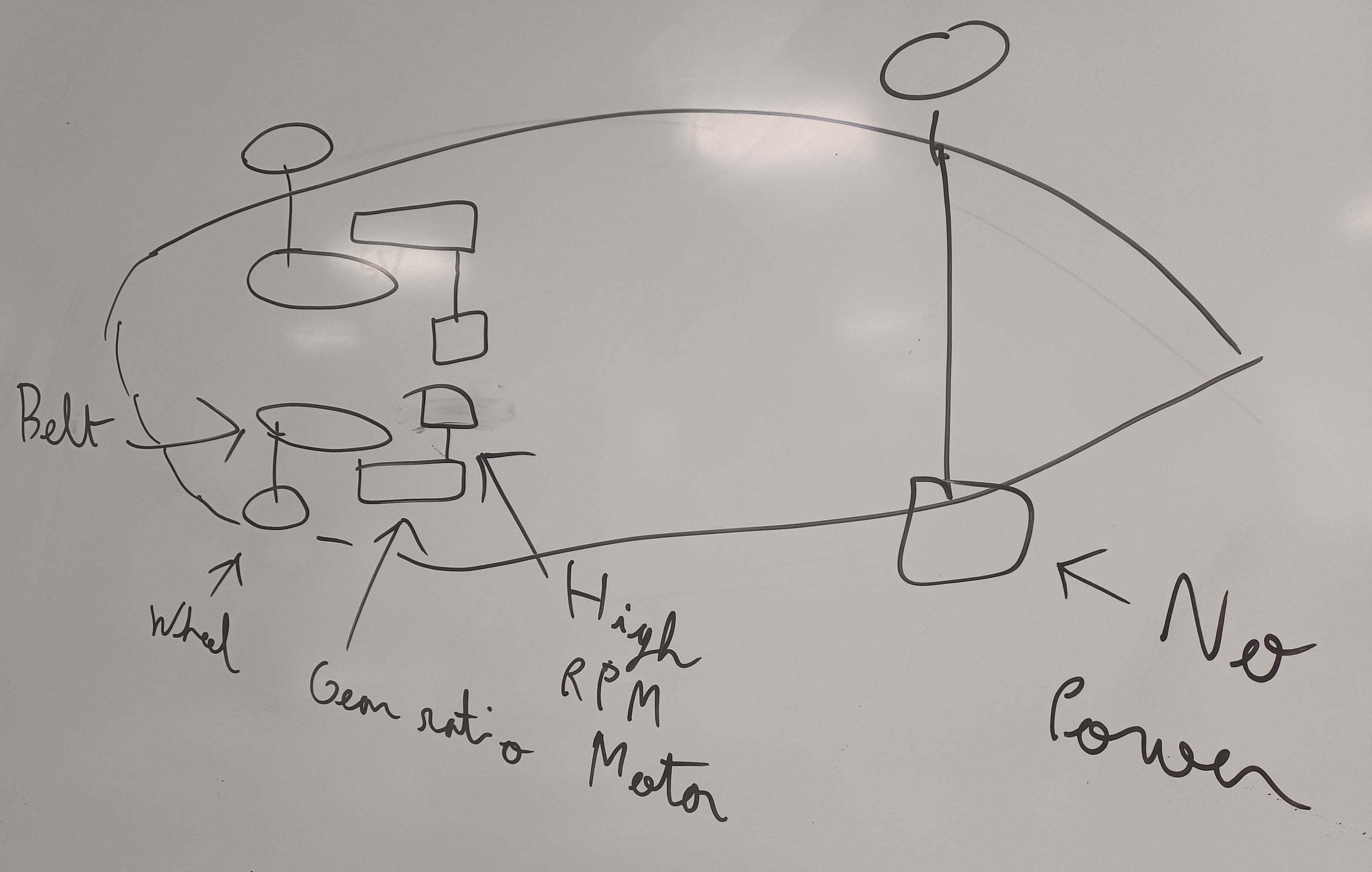
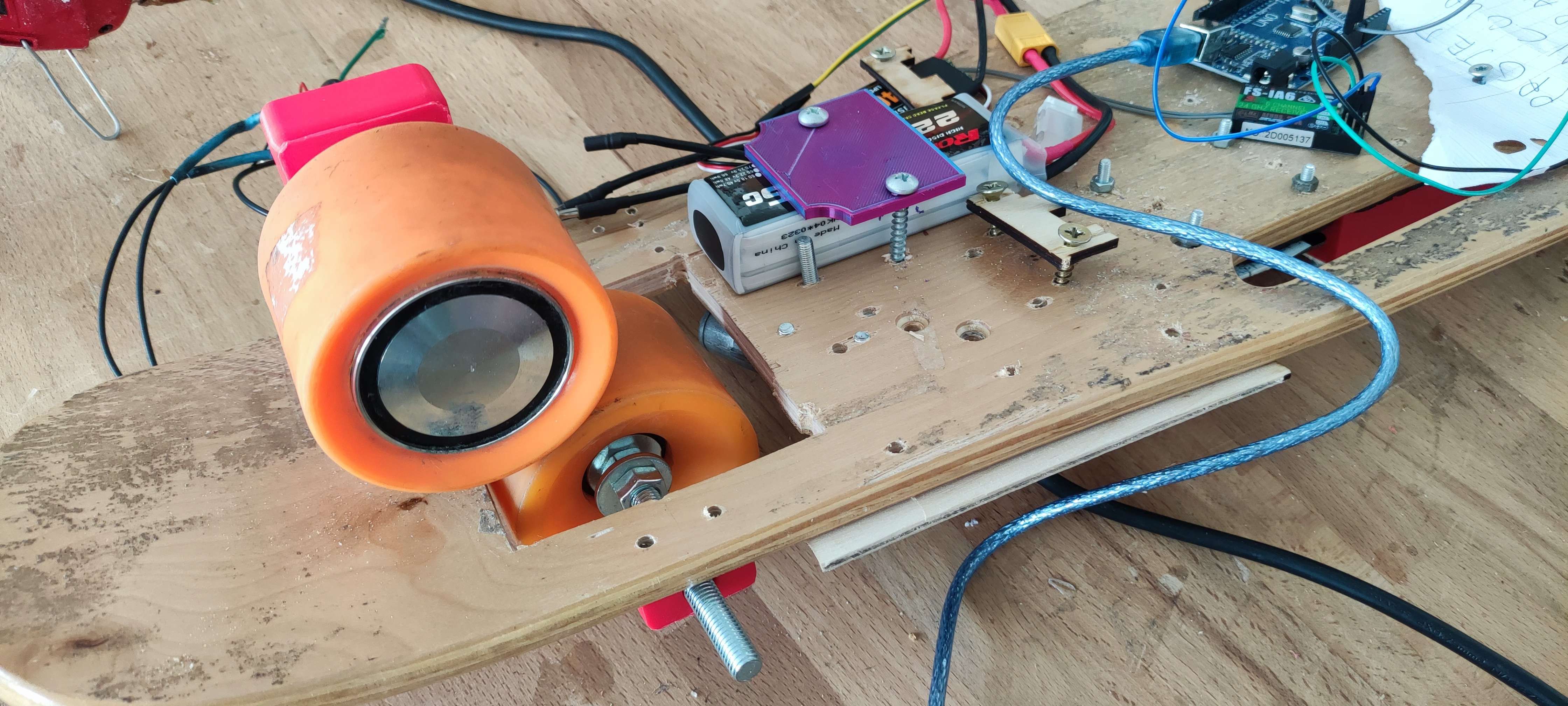
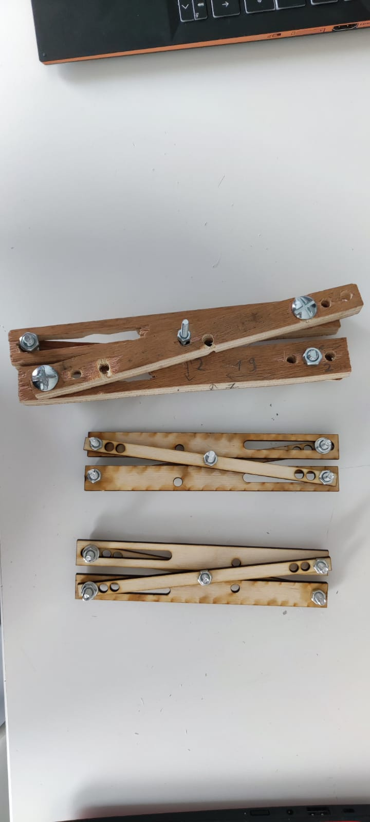
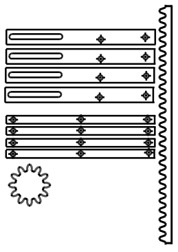 The mechanism is a combination of the these, with the first one creating the horizontal movement necessary for the second one to work and lift the structure.