In today's class, we assembled the train with the motor into the support piece we designed in the previous class. However, we did not consider the placement of the motor beforehand, so we had to perform reverse engineering to determine where to place the motor so that it would have enough torque to turn it. We have redesigned a compact piece to fulfill this function and also to hold the axis that moves the drive gear, ensuring that it remains properly aligned in its place.
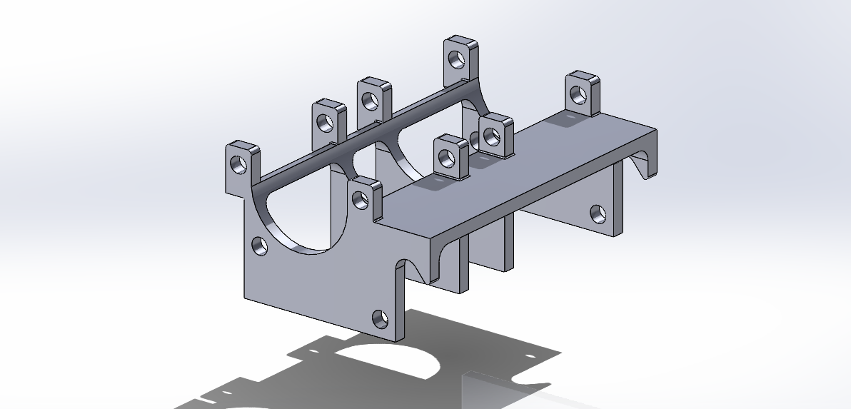
Support piece where the motor is mounted, featuring a geometry that locks the drive gear's shaft in position, preventing it from moving upward or coming off the axis
Furthermore, when testing the functionality of the train, we detected that the big motor that moves the whole device, rotated in its own axis, making the wires tangled and eventually not performing well enough with the gears at times. As for solving this problem, we redesigned the following piece below. This piece now secures the big motor, making the motor completely fixed even in its own axis. As you can see has two sets of holes. The inner holes are for inserting screws to prevent the motor from rotating around its own axis. The outer holes are for screwing the piece to the base where the motor is mounted. Additionally, we made a "counter sunk," which is a type of recess that allows the screw to be hidden. We did this because if the screw was not hidden, the drive gear would rub against it while turning, preventing the wheels from rotating properly and causing the motor to get stuck as well.
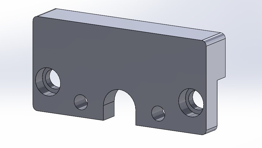
Piece that secures the main motor from the wheels
Additionally, we designed a trailer to hold the battery. We crafted a geometry that would fit and attach to the train without compromising its appearance. However, when printing the trailer, we initially did not account for the cables or the necessary tolerances for a proper fit, so we had to reprint it after making the necessary adjustments to ensure everything fit perfectly. Once redesigned, the switch and cables fit as intended. We also created a clipping mechanism to optimally attach the trailer to the train. We considered having a whole where to pass the wires through and another one for placing the switch button.
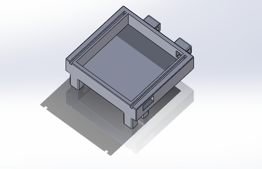
Trailer for the batteries
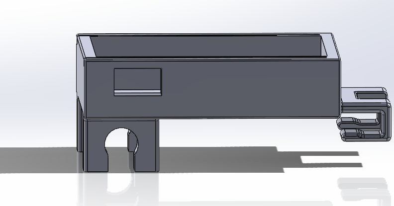
Detail of the clip mechanism for attaching it to the rest of the train assembly
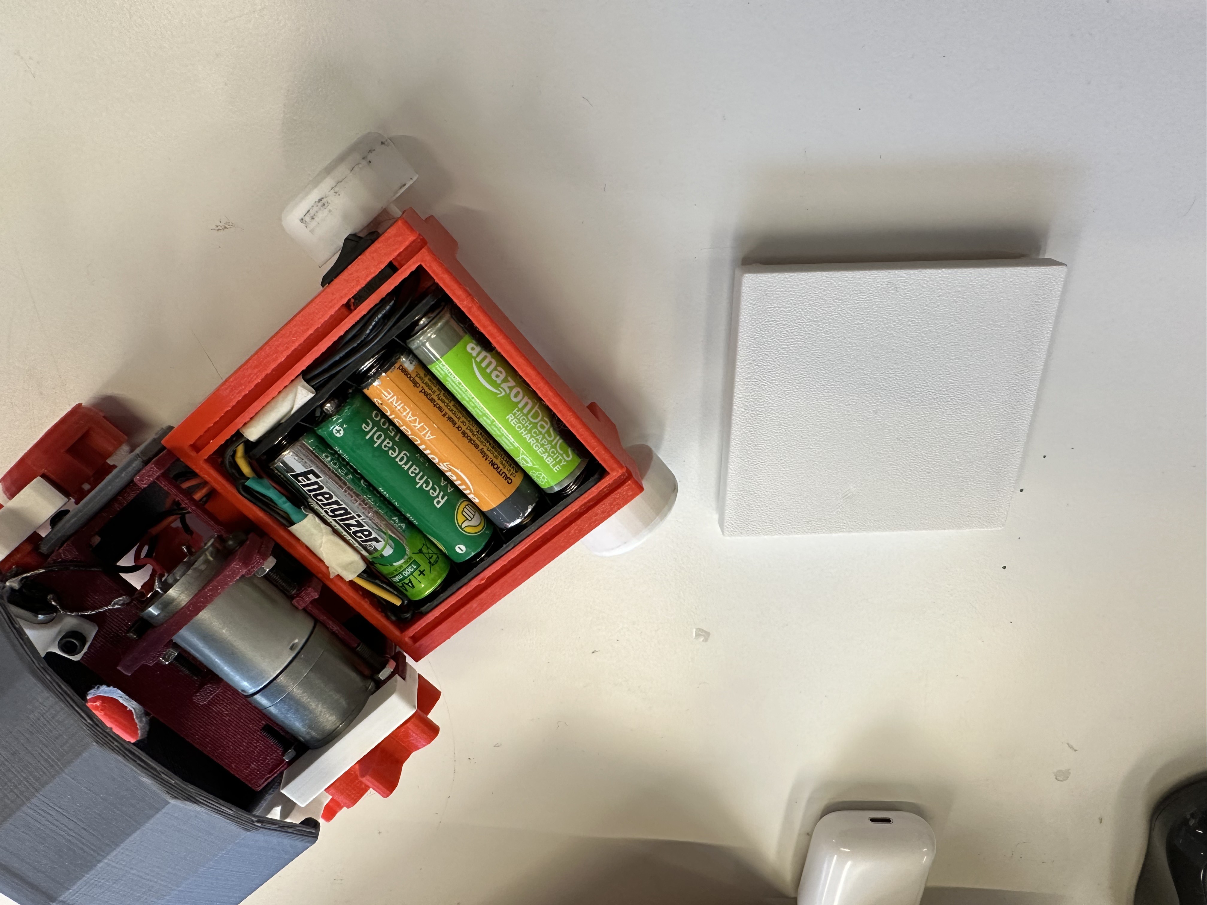
White lid for hiding the battery

The motor support is assembled with the new piece that fixes the motor, the drive gear, and the trailer where the where the battery will be hidden
At this point, the train was operational, with the drive gear enabling movement. However, we wanted to improve so we focused on the large central axis, which initially featured blades intended to be driven by the gears. Due to a design flaw, these blades caused the train's movement to stuck. Therefore, we redesigned the axis without the blades and added two more gears (one in the tiny motor and one in the central axis) to automate the axis and display the smoke cam follower.
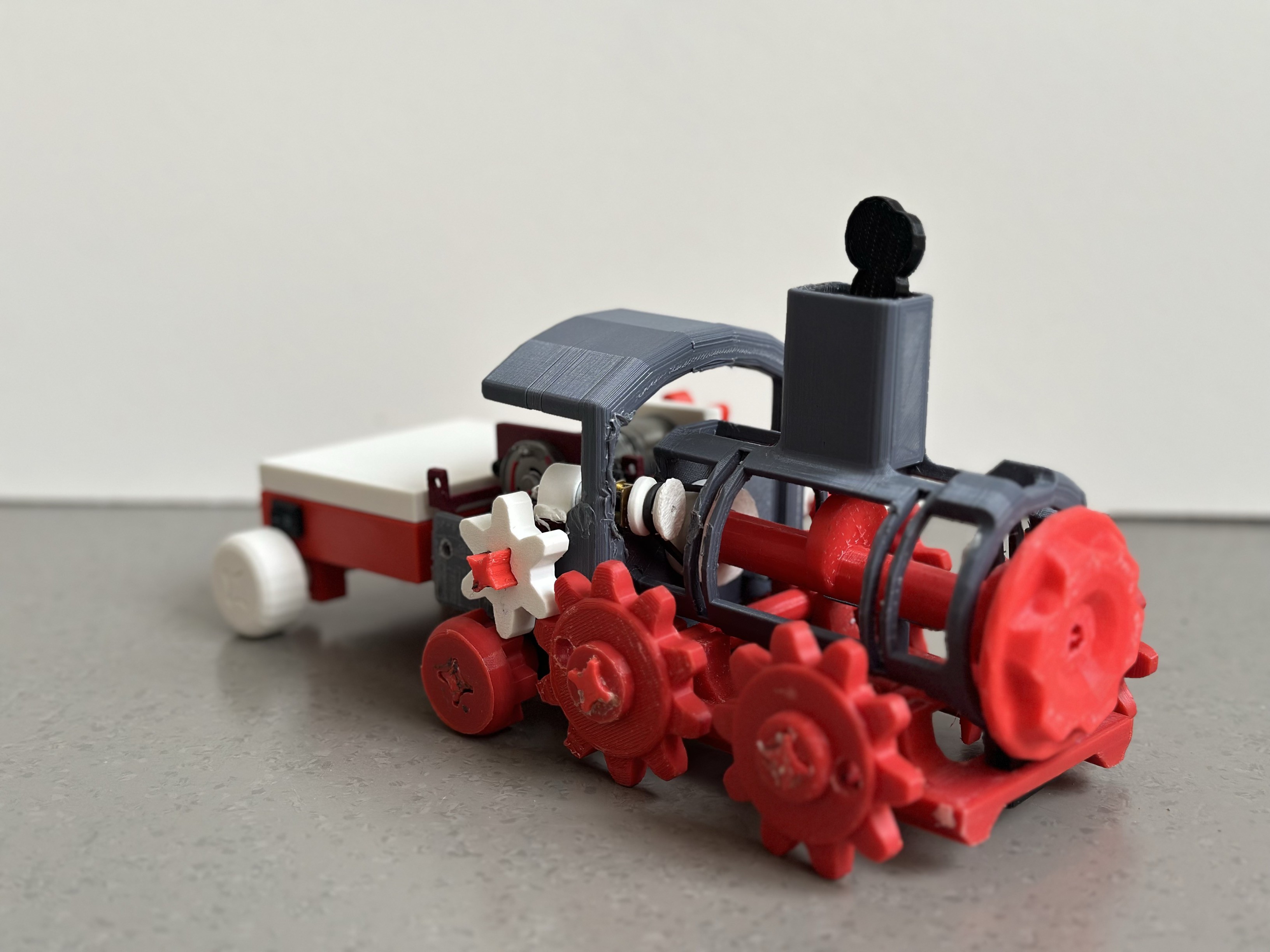
Central axis assembled with its respective wheels connected to the motor
These gears needed to be placed at a specific distance to accommodate a sufficiently taut rubber band, ensuring smooth rotation without slipping.
In terms of speed, we needed to consider what gear/wheel needed to be the bigger one. The central axis should have the big gear and the little gear should be fit in in the little motor. ¿Why did we assign the gears this way? Because this means that when the gear of the little motor completes one rotation, the bigger gear will not have completed one, ensuring it moves more slowly. So for the reason we will put the smaller gear connected to the motor and the bigger in the axis.
Distance between the wheels to enable movement
After implementing this, we overlooked the fact that we also needed to attach in some way this little motor to the big motor's support. To solve this problem, we designed one of the mounting pieces to include screws, securing the piece to the motor to prevent it from moving in any direction, thus allowing the motor to function correctly.
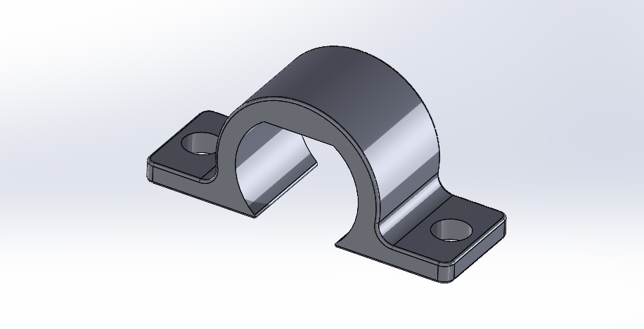
Piece that holds and secures the small motor
Regarding the batteries, since we have two motors but not enough space to accommodate two batteries, we decided to power both motors using a single battery. To achieve this, we connected the positive wires from both motors, soldered them together, and then soldered them to the positive terminal of the battery. Similarly, we connected the negative wires from both motors, soldered them together, and then soldered them to the negative terminal of the battery.
Finally, after all these updates in the train's CAD, we achieved a fully functional device that could move by itselft when turning power on.
Discussions
Become a Hackaday.io Member
Create an account to leave a comment. Already have an account? Log In.