Close
0%
0%

nedoPC-85

Started in 2004 as a simple breadboard-friendly computer on Intel 8085 microprocessor...

Public Chat
Similar projects worth following
In June 2004 I designed very simple "computer" around Intel 8085 microprocessor (enhanced version of 8080 with a single power supply and multiplexed bus). Here I will document attempt to make a Tindie product based on this design...

Main board nedoPC-85-A designed by me in 2004:
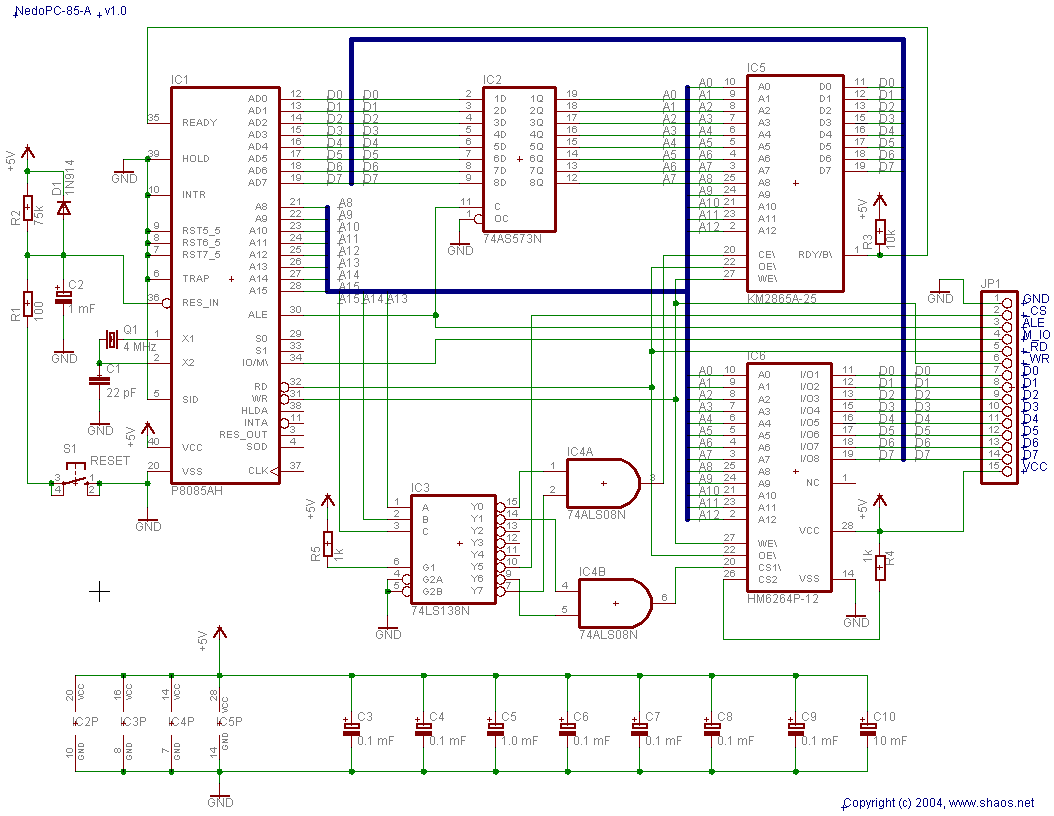
Memory map of nedoPC-85 (8 regions 8KB each):

Address RangenedoPC-85-A (2004)nedoPC-85-MK (2018)
0000...1FFFROM 8KB (IC5)ROM 8KB (IC5)
2000...3FFFRAM 8KB (IC6)RAM 8KB (IC6)
4000...5FFFnot used 2nd RAM 8KB
6000...7FFFnot used External memory
8000...9FFFnot used Keyboard reading
A000...BFFFExtension bus NI-15Extension bus NI-15
C000...DFFFRAM 8KB (IC6) - mapped 2000...3FFFRAM 8KB (IC6) - mapped 2000...3FFF
E000...FFFFROM 8KB (IC5) - mapped 0000...1FFFROM 8KB (IC5) - mapped 0000...1FFF

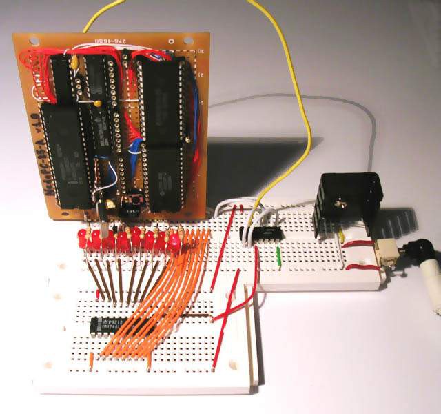
Test board for interface NI-15 (NI = nedoInterface) that blinks LEDs:
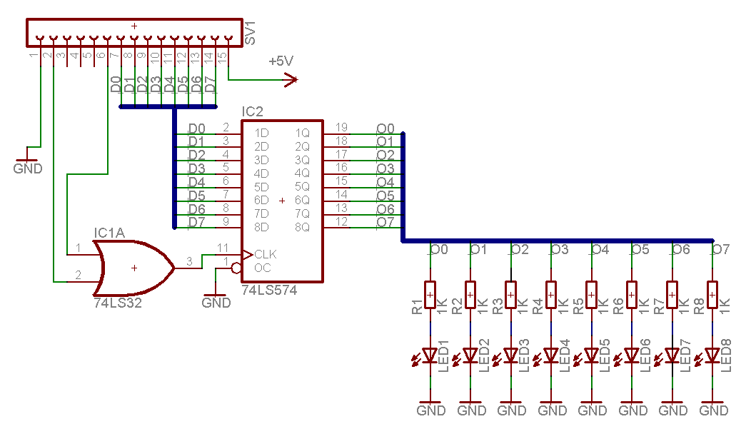
These schematics represent test setup pictured below (2004):

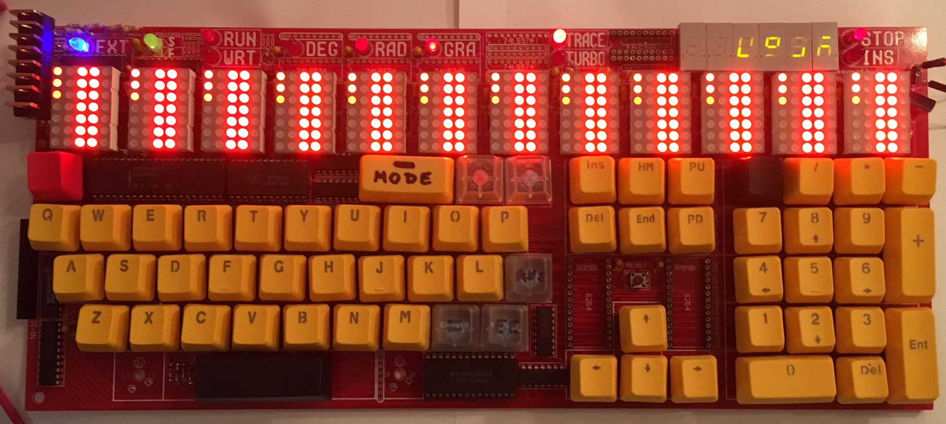
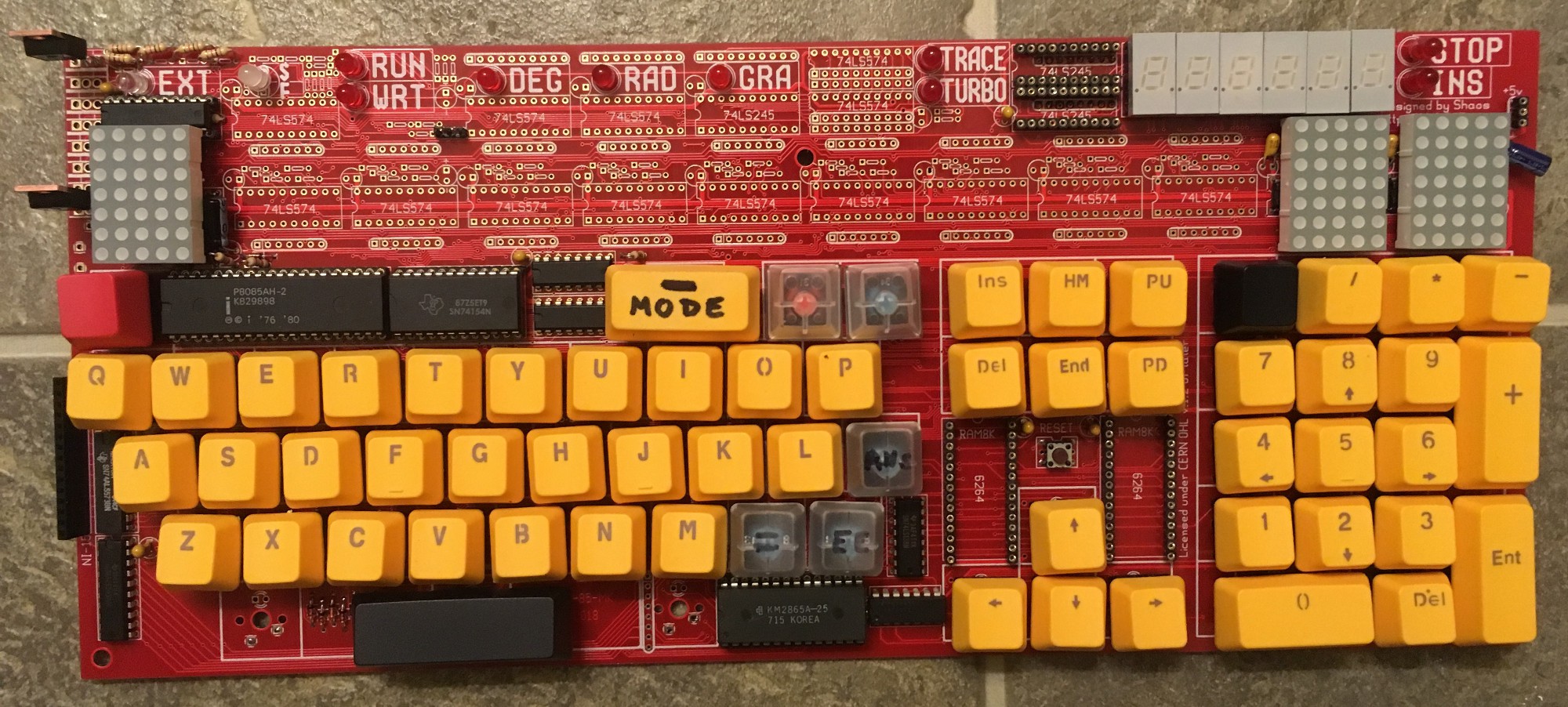
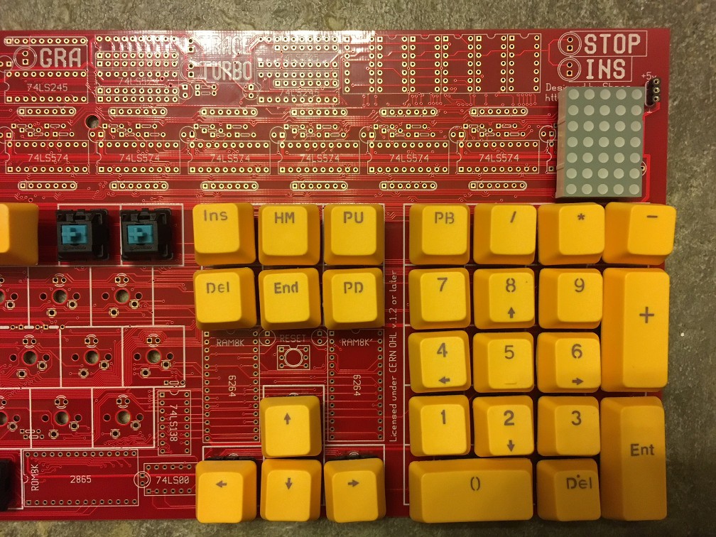
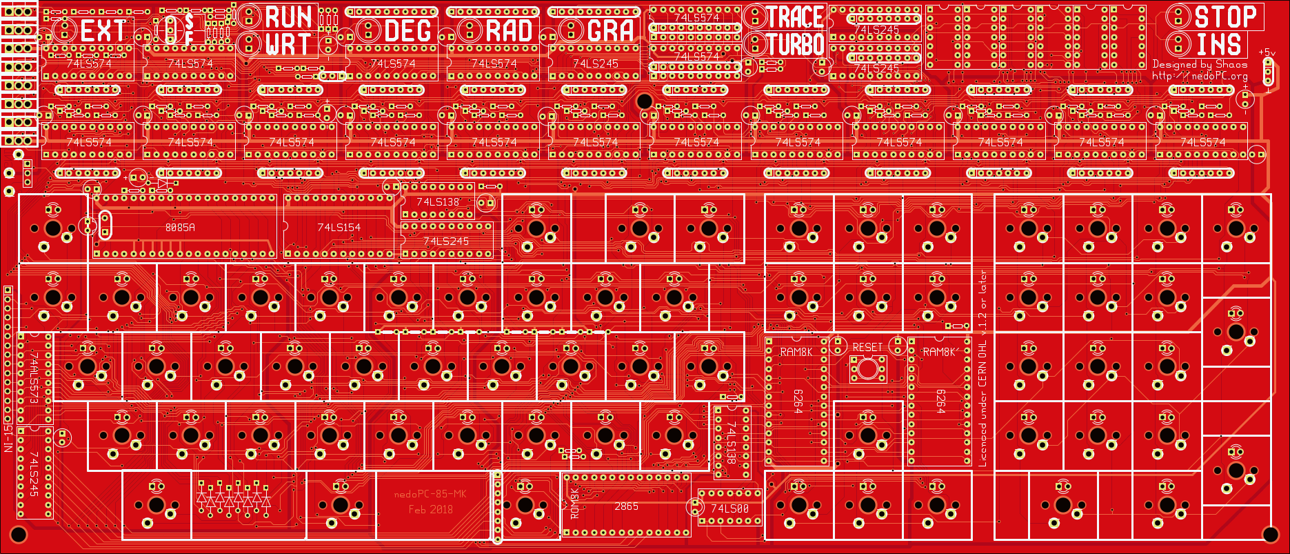
14 years later, in January 2018, I started working on extended version called nedoPC-85-MK that includes Cherry-MX keys and 5x7 LED matrix display (12 characters) plus some additional LEDs and 7-segment indicators:
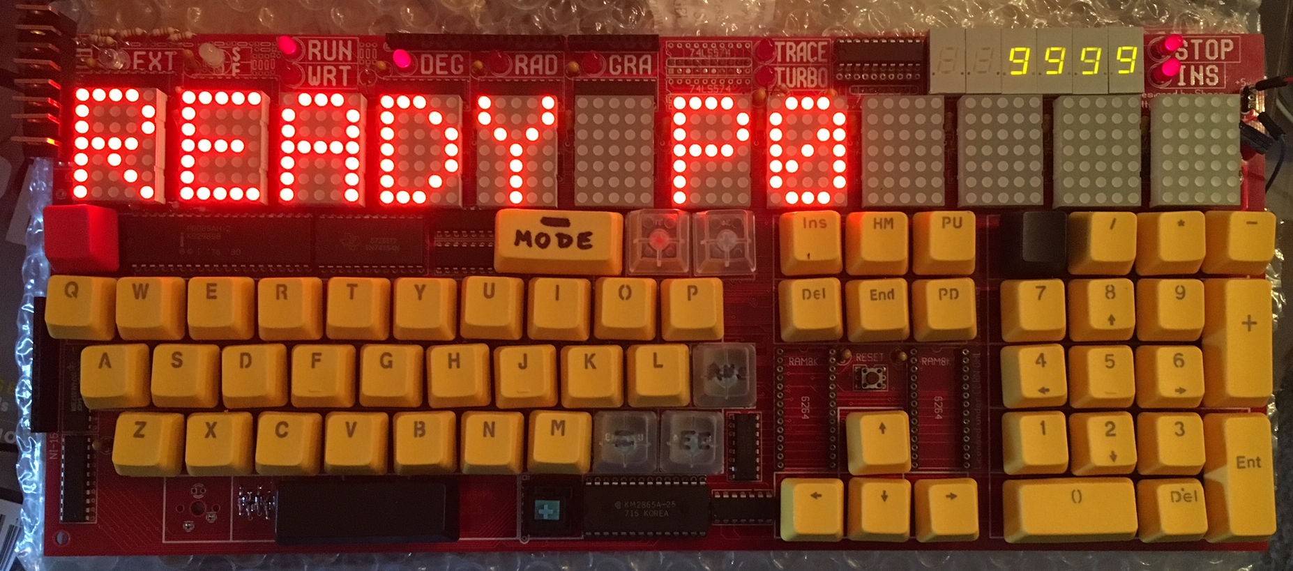
It intentionally resembles Elektronika MK-85 look, but in order to be a true MK-85 clone it should have PDP-11 compatible backend from my another project #PDPii (and in this case 8085 will work only as a controller of display and keyboard).

  • Details on keyboard

    SHAOS04/09/2018 at 01:24 4 comments

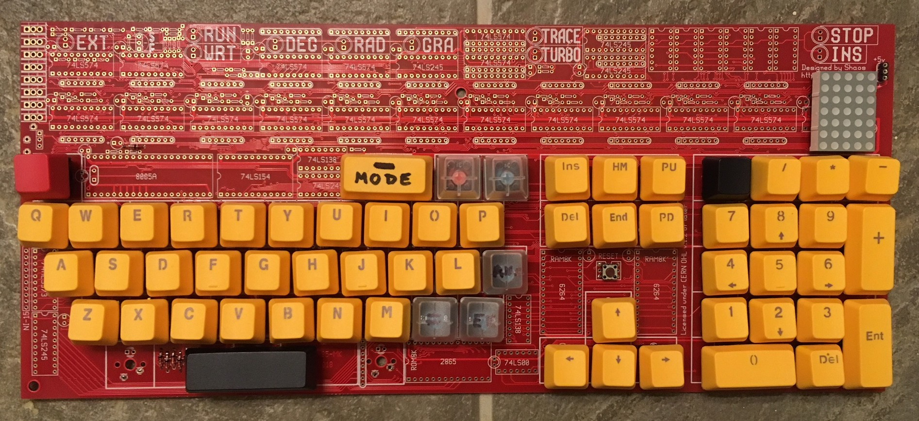
    Keyboard is connected similarly to ZX-Spectrum - 8 bits from address bus ( other bits by the way ; ) trough diodes goes to key matrix and come back through data bus (if address space is 0x8000...0x9FFF):

    data bus bits ======>
    01234567
    bit 0 from address bus
    [S][F]ENTER+-HomeEndRESET
    bit 1 from address busO ;
    P ,
    .369*(reserved)
    bit 2 from address busLANS258/PgUpPgDn
    bit 3 from address bus=EE0147AC
    (reserved)
    bit 4 from address busSTOP
    INSDELMODEUpDownLeftRight
    bit 5 from address busQ !
    W "
    E #
    R $
    T (
    Y )
    U ?
    I :
    bit 6 from address busASDFGHJK
    bit 7 from address bus
    ZXCVBNMSPACE

    Scanning is done by reading from memory range 0x8000...0x9FFF and "0" in any address bits 0...7 will be retranslated into data bus if any key in that row is pressed. Recommended way to read from keyboard is reading from 8 address locations - 0x9FFE (bit 0 is zero), 0x9FFD (but 1 is zero), 0x9FFB (bit 2 is zero), 0x9FF7 (bit 3 is zero), 0x9FEF (bit 4 is zero), 0x9FDF (bit 5 is zero), 0x9FBF (bit 6 is zero) and 0x9F7F (bit 7 is zero). If nothing is pressed byte FF will be read. Otherwise proper bit will be reset to indicate which particular key was pressed. For example:

    LDA 9F7F ; read 7th row (bit 7 is zero) to A
    ANI 80H ; mask 7th bit in response
    JZ SPACE ; jump if zero - SPACE pressed 
    

  • 8085 code to display static text

    SHAOS04/05/2018 at 06:56 0 comments

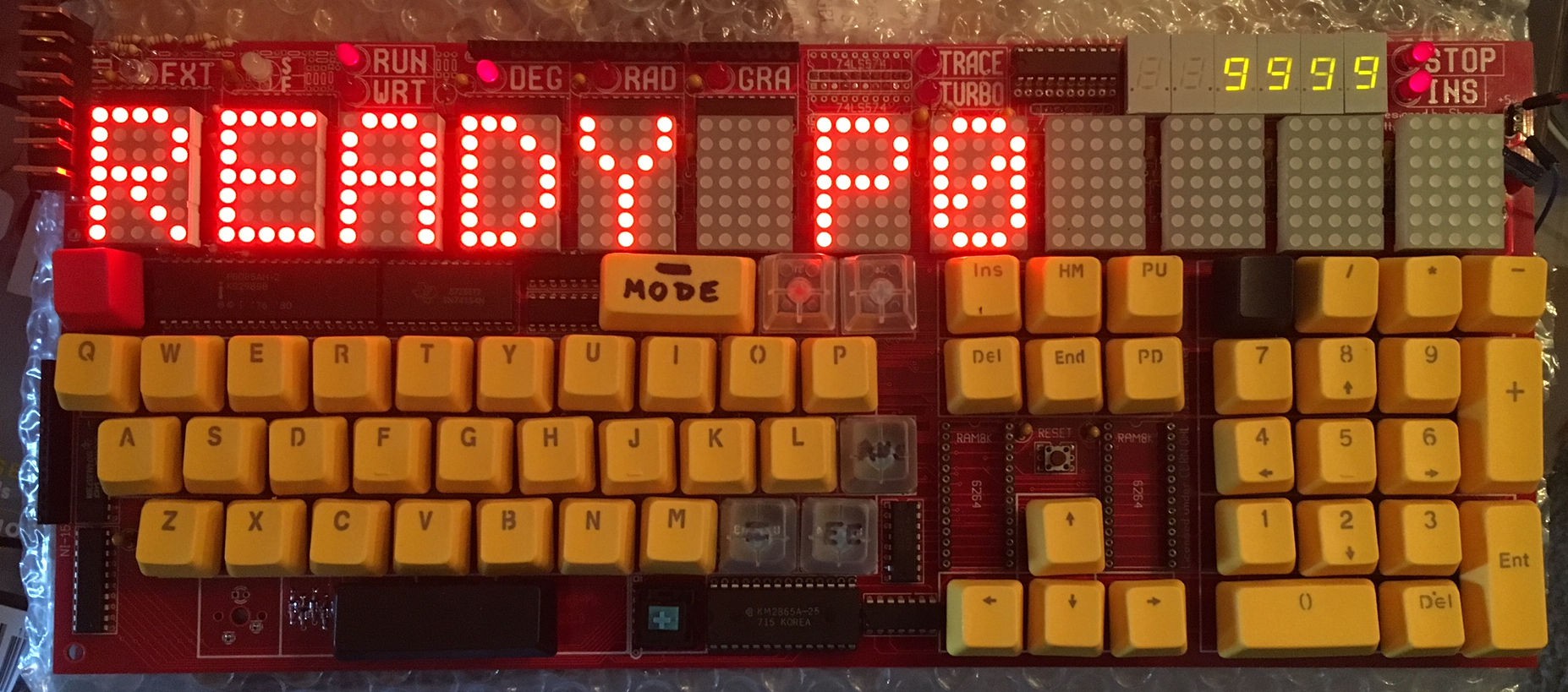
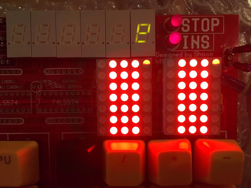
    In order to show something on the screen (something static as READY P0 from one of the pictures) we need to repeat below code 8 times - for every horizontal of the screen (LEDs and 7-segment indicators are horizontal 0):

    3E MVI A,10h ; write XXXXO to 1st register
    10
    D3 OUT 1
    01
    3E MVI A,00h ; write XXXXX to 2nd register
    00
    D3 OUT 2
    02
    3E MVI A,11h ; write OXXXO to 3rd register
    11
    D3 OUT 3
    03
    3E MVI A,18h ; write XXXOO to 4th register
    18
    D3 OUT 4
    04
    3E MVI A,0Eh ; write XOOOX to 5th register
    0E
    D3 OUT 5
    05
    3E MVI A,1Fh ; write OOOOO to 6th register
    1F
    D3 OUT 6
    06
    3E MVI A,10h ; write XXXXO to 7th register
    10
    D3 OUT 7
    07
    3E MVI A,11h ; write OXXXO to 8th register
    11
    D3 OUT 8
    08
    3E MVI A,1Fh ; write OOOOO to 9th register
    1F
    D3 OUT 9
    09
    3E MVI A,1Fh ; write OOOOO to 10th register
    1F
    D3 OUT 10
    0A
    3E MVI A,1Fh ; write OOOOO to 11th register
    1F
    D3 OUT 11
    0B
    3E MVI A,1Fh ; write OOOOO to 12th register
    1F
    D3 OUT 12
    0C
    3E MVI A,0FDh ; 11111101 <<<< highlight proper horizontal line (here it's 1st one)
    FD
    D3 OUT 0
    00
    3E MVI A,100 ; wait 100 times (1400 cycles or 0.56 ms in case of 2.5 MHz clock)
    64
    3D DCR A <---\
    CZ JNZ ------/
    XX
    XX
    3E MVI A,0FFh ; 11111111 <<<< remove indication
    FF
    D3 OUT 0
    00
    ; and so on for FB,F7,EF,DF,BF,7F and FE (LEDs and 7-segments)


    As you can see this code works from ROM and doesn't need RAM at all, so all displayed text (that's actually graphics) is hard-coded into the code

    It's refreshing whole screen about 190 times per second

    P.S. I created a public chat for this project: https://hackaday.io/messages/room/229637

  • External memory connector?

    SHAOS04/01/2018 at 01:34 4 comments

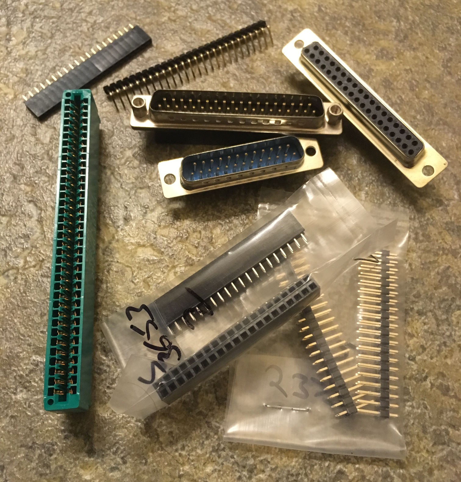
    As you can see I plan to have 8K of external memory (like a cartridge or something) in the address range 0x6000...0x7FFF, so question is - what should it be physically? Connector must have 2 power signals (+5V and GND), 13 address signals (to cover 8K address range), 8 data signals and also 3 control signals: /CS, /RD, /WR, so total is 26. 

    Should it be 1 row of pins? 2 rows of pins? Male? Female? D-SUB connector? Edge connector? Or may be something else? Please share you thoughts in comments below! Thank you ;)

  • Keyboard test

    SHAOS03/28/2018 at 05:26 2 comments

    Now time to print something:

    and test keyboard :)

  • More lights

    SHAOS03/24/2018 at 07:43 0 comments

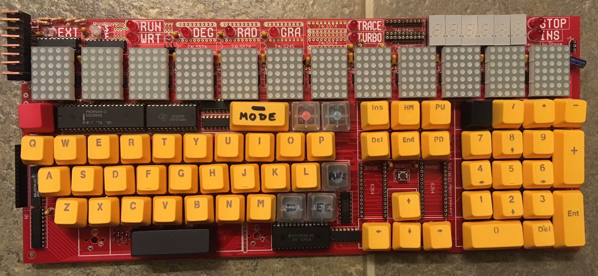
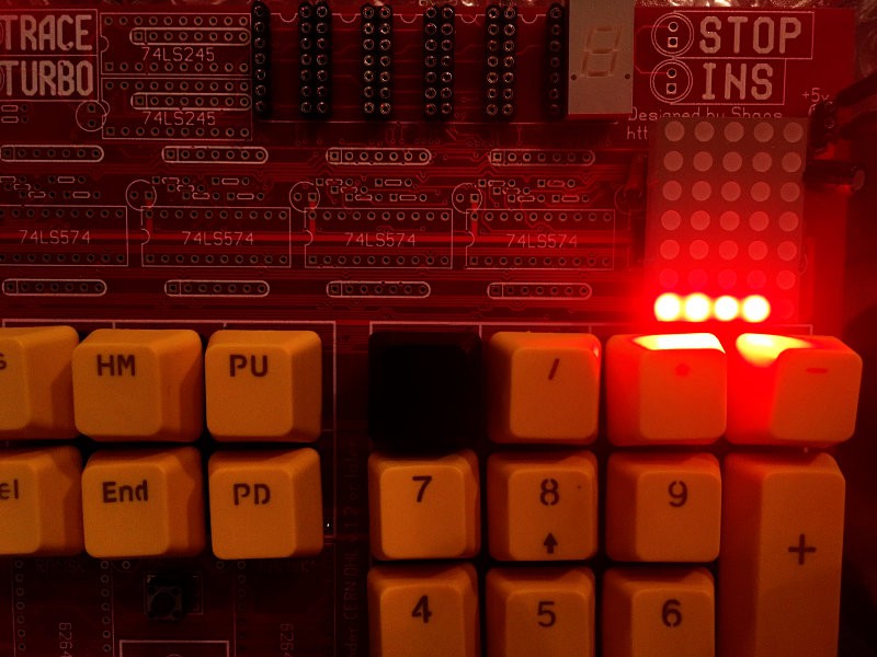
    all 5x7 LED matrix installed:

    and it's working :)

    video:

    it executes this program (and eats 500-900 mA):

    .i8080
       org   0
       mvi   a,0FFh
       out   0
       mvi   b,0
    loop:
       mov   a,b
       rrc
       rrc
       rrc
       out   1
       out   2
       out   3
       out   4
       out   5
       out   6
       out   7
       out   8
       out   9
       out   10
       out   11
       out   12
       inr   b
       nop
       mvi   c,9
       mvi   d,7Fh
    loop1:
       mov   a,d
       out   0
       stc
       rar
       mov   d,a  
       lxi   h,100
    loop2:   ; total 24
       dcx   h      ; 5
       mov   a,h    ; 5
       ora   l      ; 4
       jnz   loop2  ; 10 
       dcr   c
       jnz   loop1
       jmp   loop

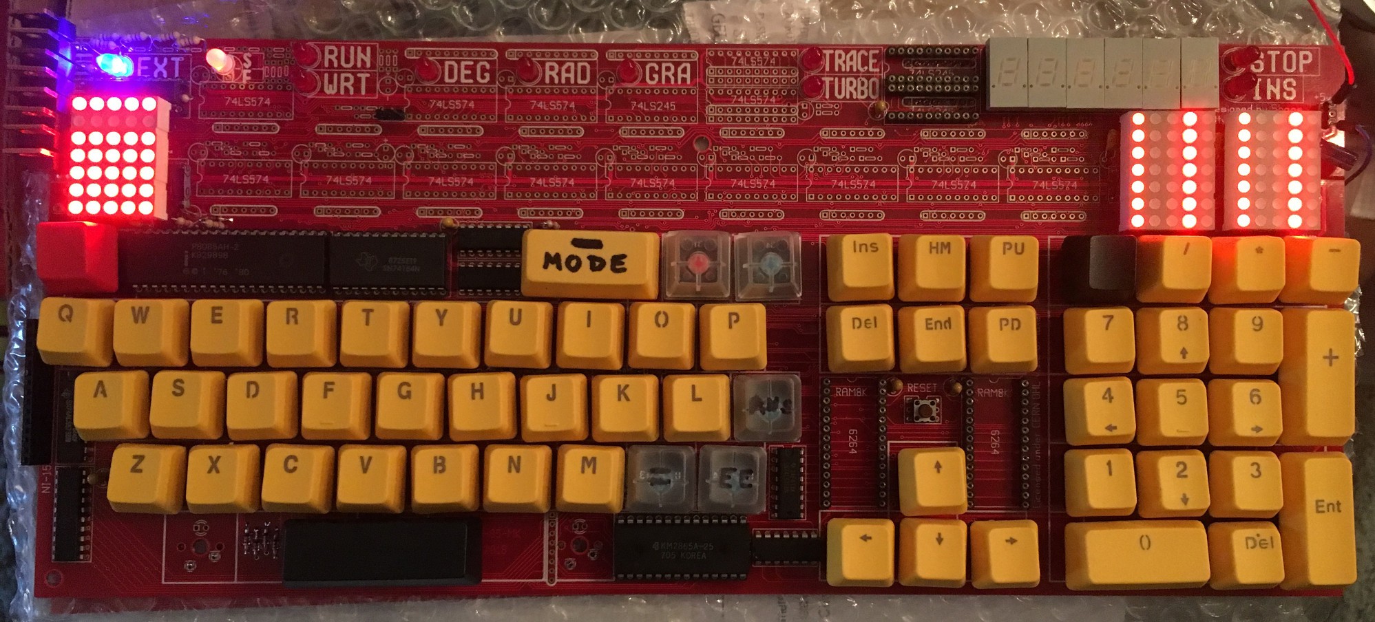
  • Lights

    SHAOS03/18/2018 at 23:03 2 comments

    And it's time to fire some lights :)

    This test eats up to 450 mA

    P.S. Still waiting for other components to finish all 12 characters of the display...

  • Cherry MX

    SHAOS03/14/2018 at 05:51 0 comments

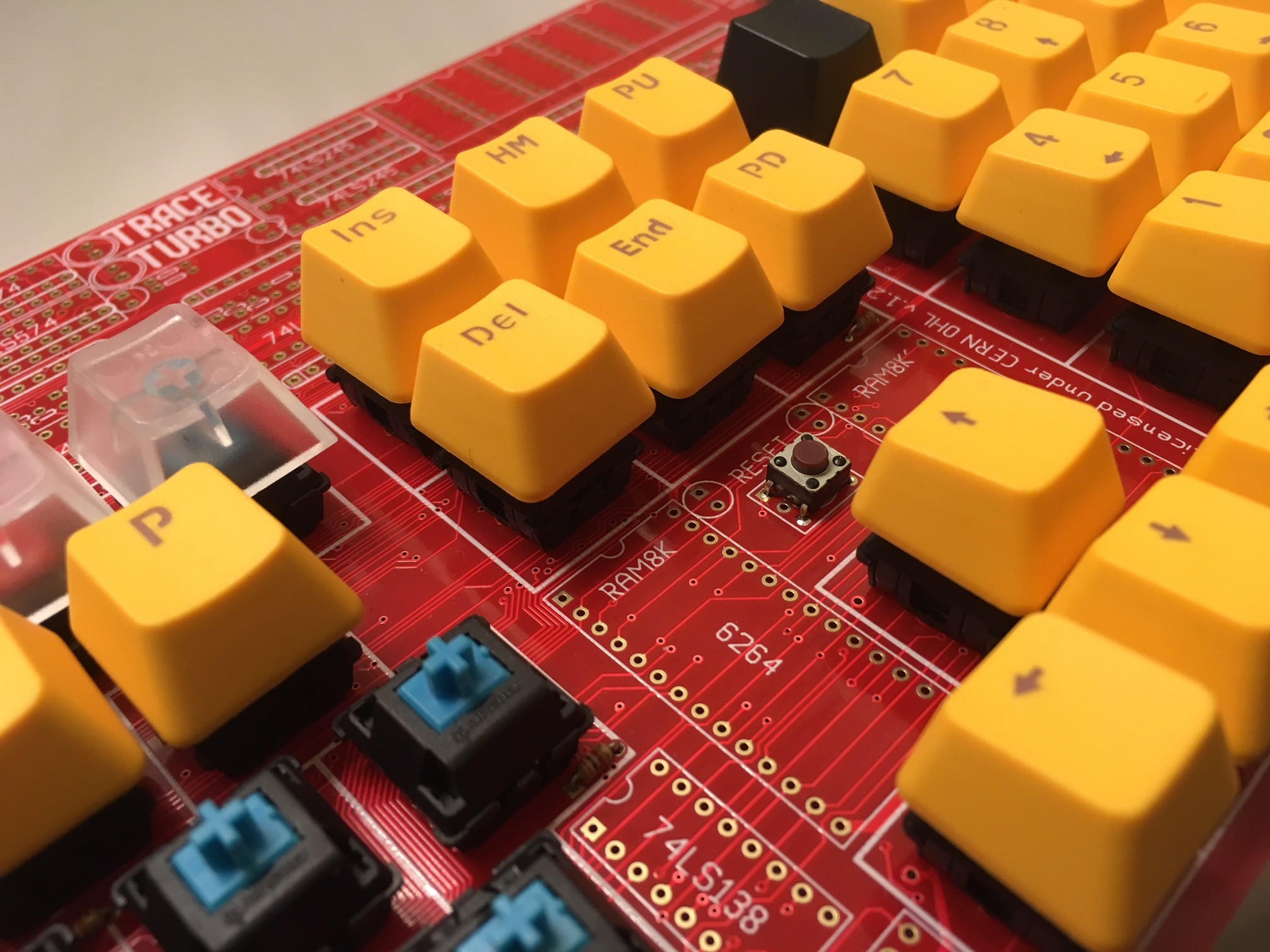
    Here I use Cherry MX keyswitches:

    Where can I order "custom" Cherry MX caps? Handwriting doesn't look right :)

    P.S. It looks like I've just found the way: 

    http://www.wasdkeyboards.com/index.php/products/printed-keycap-singles/custom-text-cherry-mx-keycaps.html

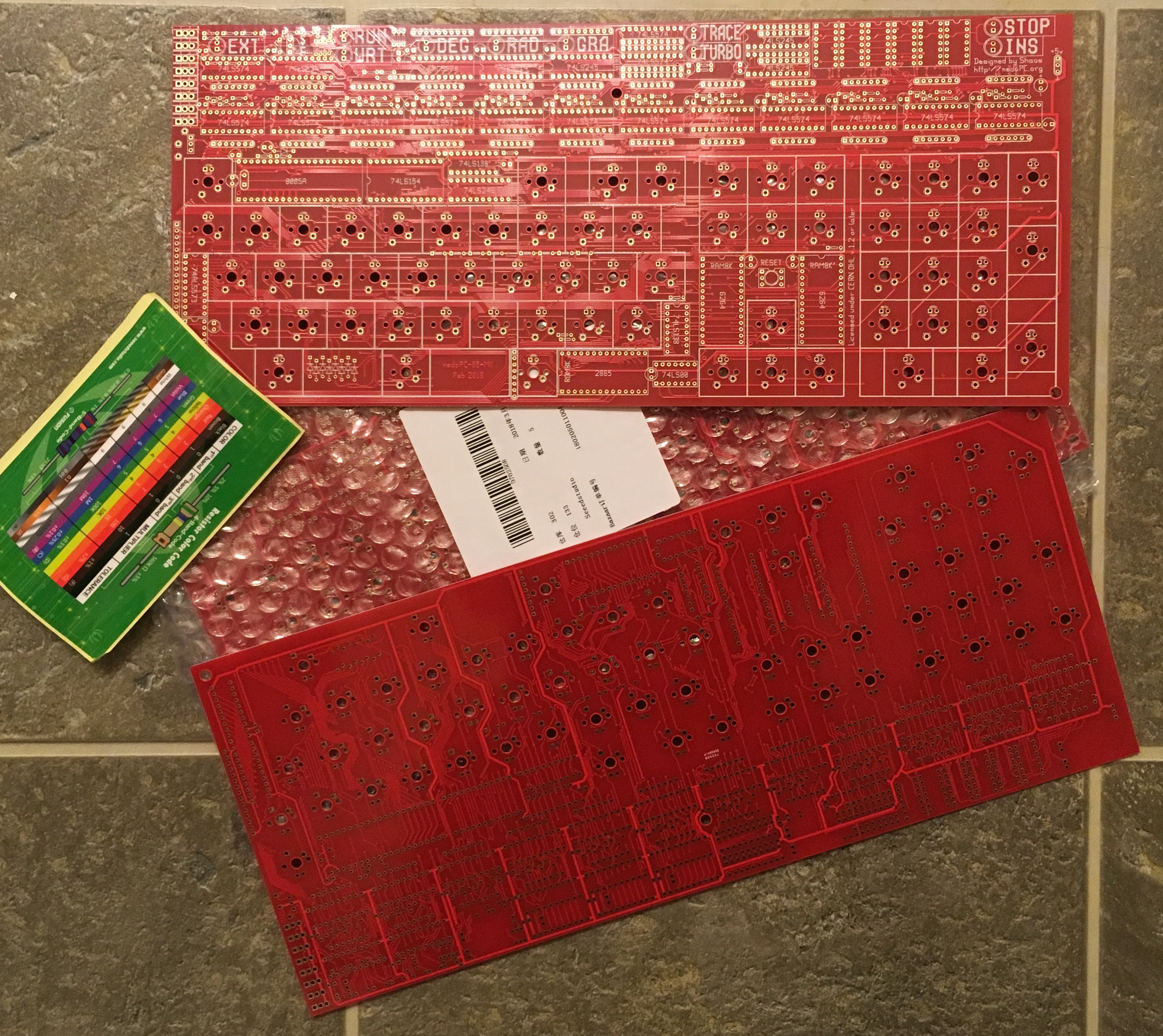
  • nedoPC-85-MK v1.0 boards received

    SHAOS03/13/2018 at 02:14 0 comments

    Now it's time to build something cool ;)

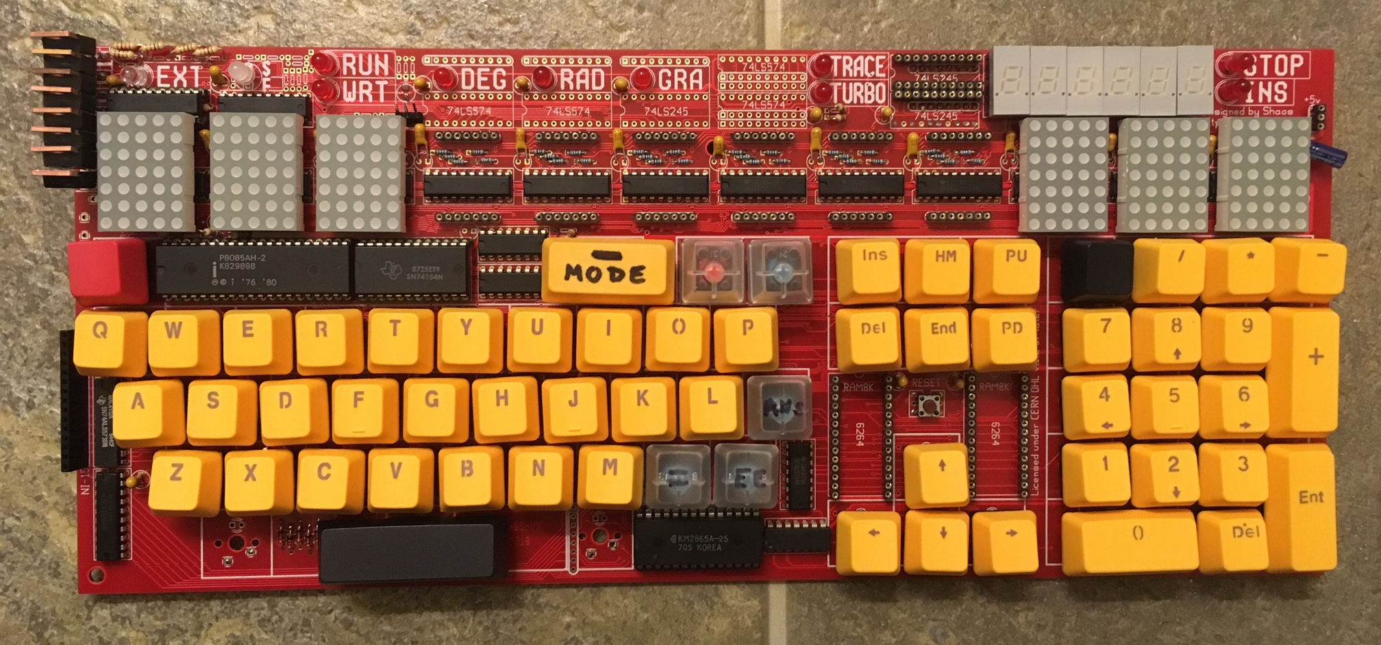
    Unfortunately I don't have schematics for this one - I drew PCB as is (using pcb from GEDA) based on original nedoPC-85-A schematics with some thoughts from my mind regarding MK85 cloning - so the thing is I started to forget my ideas, so I think now I need to reverse-engineer my own board to re-create schematics from it...

  • nedoPC-85-MK v1.0

    SHAOS02/04/2018 at 19:27 0 comments

    This one could be a standalone 8085-based computer with Cherry-MX keyboard on board, 12 5x7 LED matrices and 6 7-segment indicators with some additional indication and stereo-audio output (2 channels with 4 bit per channel):

    Intended to resemble look of Elektronika MK-85 and CASIO FX-700P (also known as CASIO PB-100 or "RadioShack TRS-80 pocket computer"), but my board is slightly bigger (14x6") and it has more PC-like keyboard layout to make it looks like a real computer with optional backlight :)

    P.S. There is a possibility to make a true Elektronika MK-85 clone from it with help of additional board with PDP-11 compatible Soviet processor 1801VM2 (still available on ebay) with original firmware (MK-85 was PDP-11 compatible pocket computer produced from 1986 to 2000 that run BASIC interpreter similar to CASIO FX-700P)...

View all 9 project logs

Enjoy this project?

Share

Discussions

Yann Guidon / YGDES wrote 03/19/2018 at 01:08 point

Oh

MON

DIEU

  Are you sure? yes | no

SHAOS wrote 03/19/2018 at 01:10 point

Wait until I connect #PDPii from behind and make Elektronika-MK85 clone out of it :)

  Are you sure? yes | no

Jasmine Brackett wrote 06/05/2017 at 16:29 point

Hey @Shaos, any updates? Are you entering this for the Hackaday Prize's "Best Product"?

  Are you sure? yes | no

SHAOS wrote 06/06/2017 at 02:29 point

may be ;)

  Are you sure? yes | no

David H Haffner Sr wrote 01/22/2017 at 14:25 point

Yes, it is true! Mark loves wire!

  Are you sure? yes | no

SHAOS wrote 01/23/2017 at 00:44 point

I love wires too, but sometimes it's too time-consuming to solder all those wires and PCB is much faster way ;)

  Are you sure? yes | no

David H Haffner Sr wrote 01/23/2017 at 08:04 point

Oh yeah, PCB is certainly faster and I love your clever design there :)

  Are you sure? yes | no

SHAOS wrote 01/24/2017 at 05:46 point

Thanks :)

  Are you sure? yes | no

Dr. Cockroach wrote 01/22/2017 at 12:28 point

I like lots of wire :-)

  Are you sure? yes | no

SHAOS wrote 01/22/2017 at 14:21 point

Finally it will be PCB for it :)

  Are you sure? yes | no

Similar Projects

Does this project spark your interest?

Become a member to follow this project and never miss any updates