Introduction
In today's world, gaining control over energy consumption is a top priority. There are two main methods for monitoring domestic energy use:
1. Current Phase Measurement using a Clamp Meter. This method utilizes clamps that attach around a single conductor to measure current flow. It's a non-intrusive approach, meaning it doesn't require interrupting the power supply.
2. In-Line Meters: These meters are installed directly into the electrical circuit, interrupting one or more phases to measure current. While effective, they require professional installation and can be less scalable for multiple circuits.
Both methods often offer an interface with a pulse output, where the pulse frequency is directly proportional to the real-time energy consumption. This allows for easy data collection and analysis.
This project provides a solution for collecting pulses from multiple meters and sending them to a database for further analysis. Additionally, since pulse outputs are also used by other types of metering systems (gas, water, etc.), this system can be easily expanded to support them.
The project
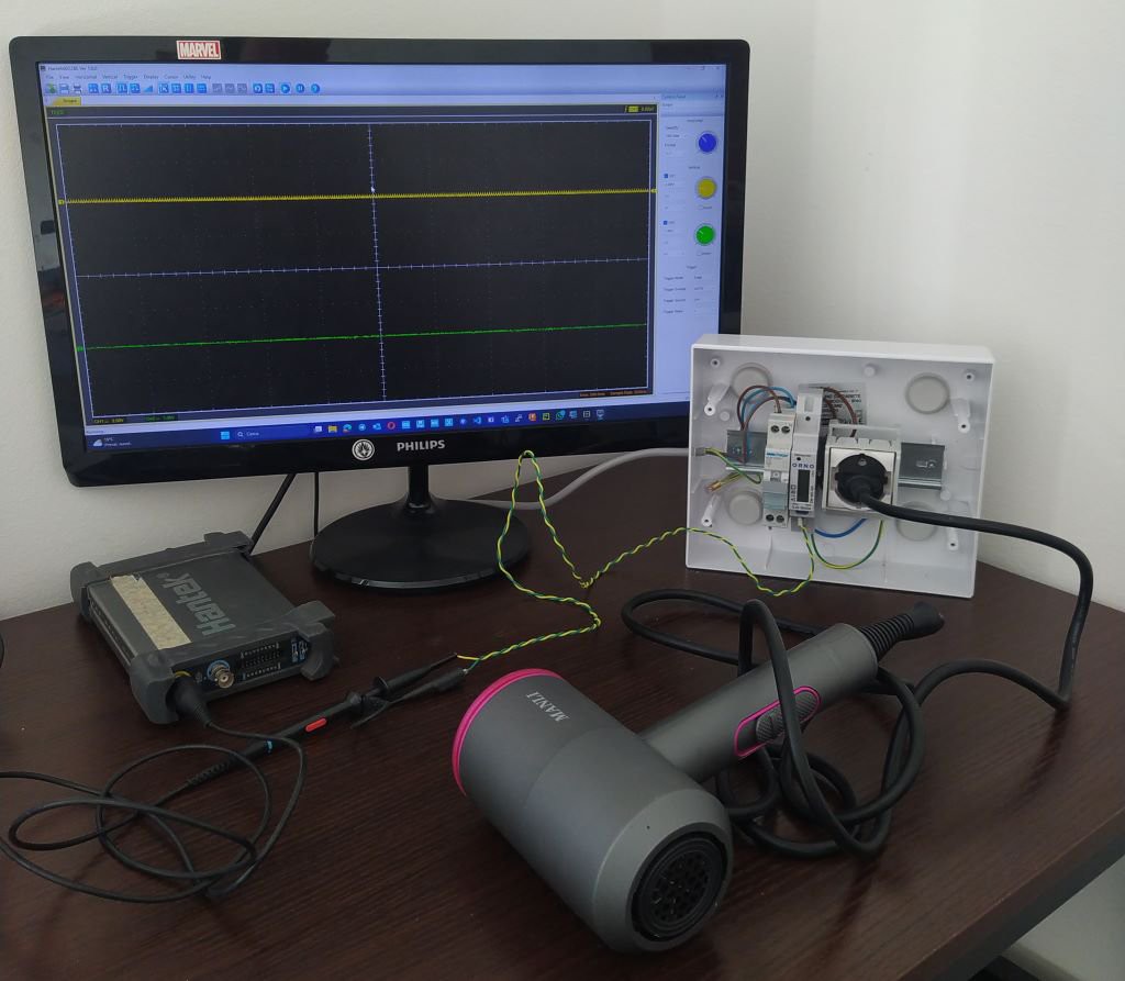
The core of the project is an ESP32-S3 microcontroller, which receives and collects pulse data from meters. After a quick online search, I couldn't find much info on the type of pulse the meters output. So, since I wasn't sure, I did some tests with an oscilloscope and a load (a hair dryer) to generate the pulses. ( however this awesome project helped me a lot openenergymonitor )
Using an oscilloscope connected to the meter, background noise can be seen when the output is not active (floating output), while a short circuit can be observed when the pulse occurs.
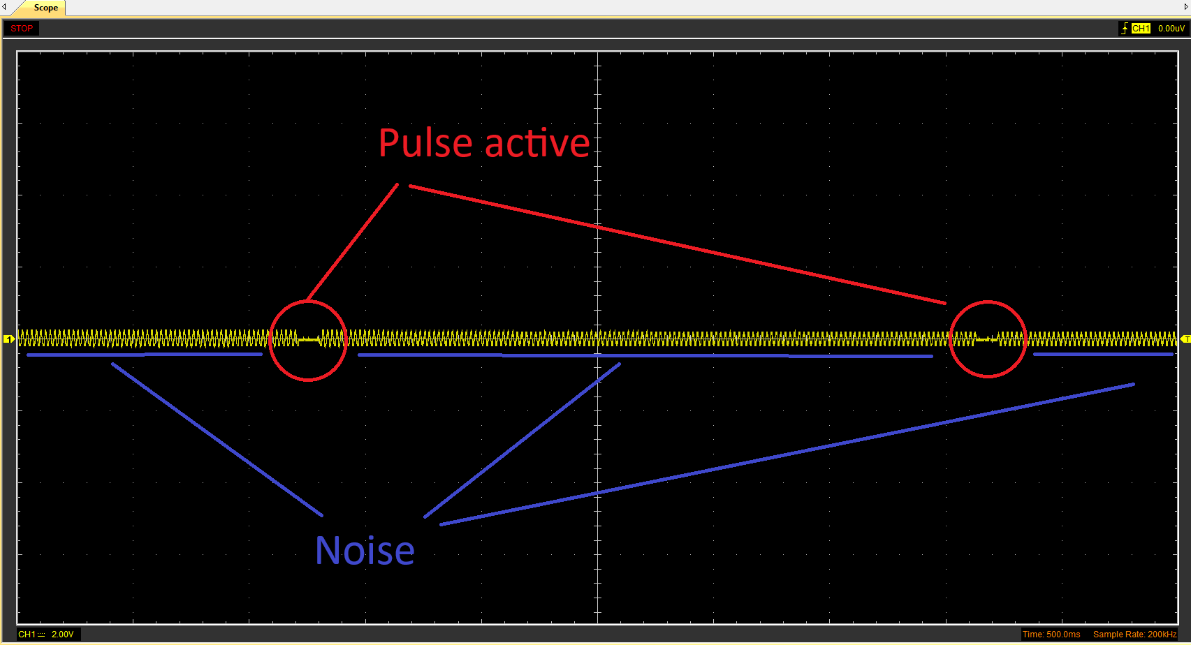
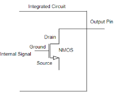
Awesome! It seems like each meter has an open-drain output style (I hope also isolate from live circuit). This is super cool because we can hook it right up to the ESP32 and just using a pull-up resistor. This will give us a nice falling edge pulse that we can easily count using interrupts.
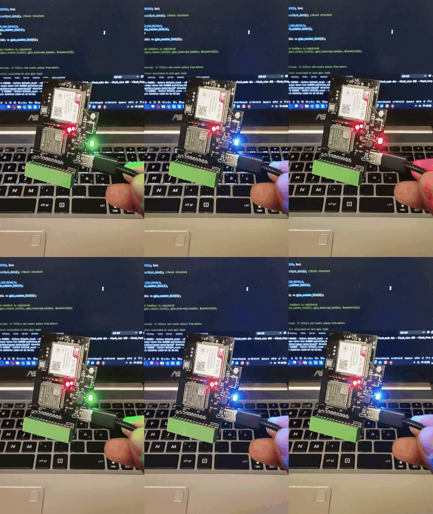
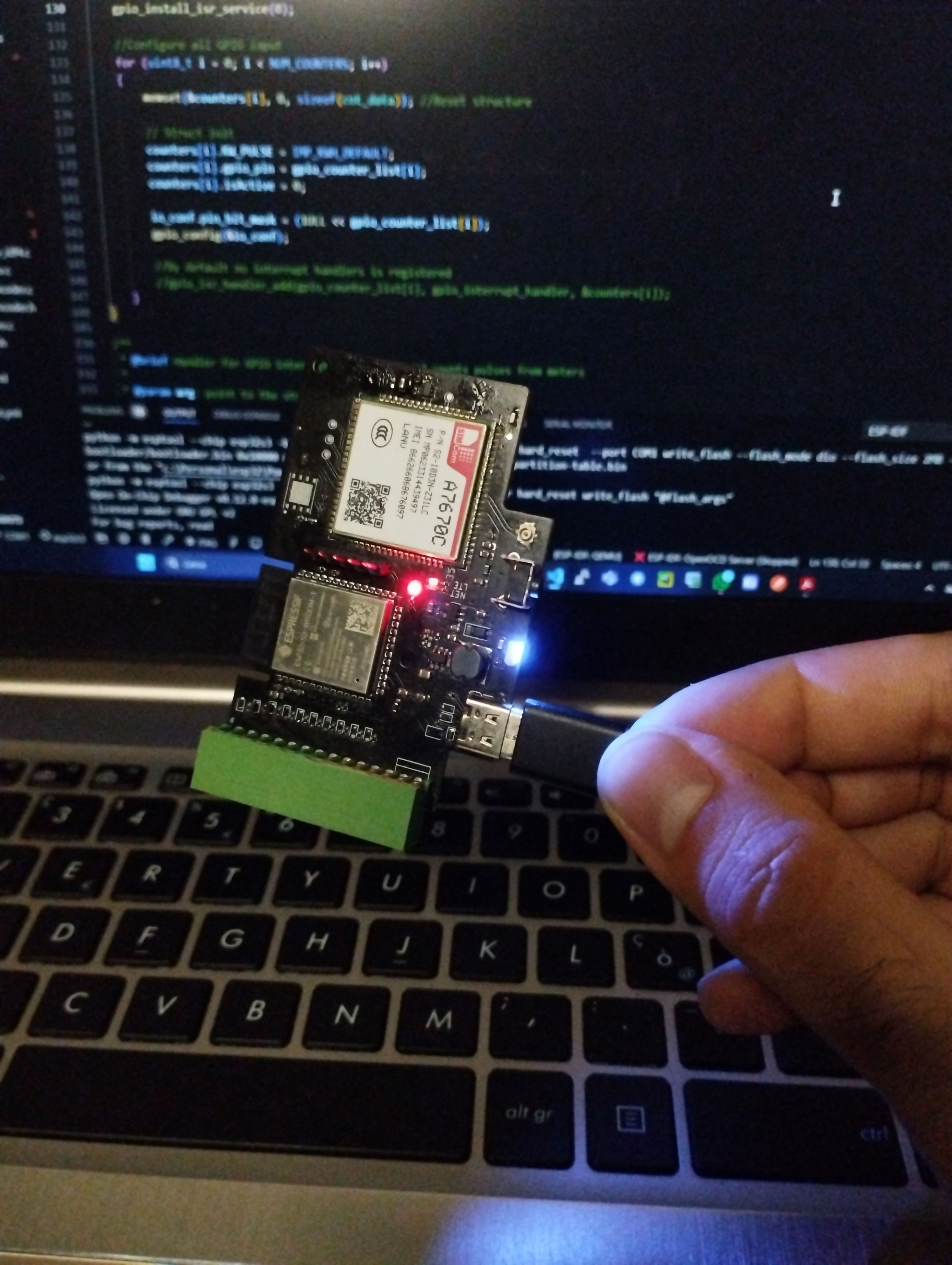
For the moment I decided to realize a demo project using a protoboard, just to test the system as a whole before realizing the final pcb. The test circuit includes a DevKit ESP32-S3, a Simcom A7670C module and connectors. That's ALL!! I decide to use internal pull-up resistors of ESP32, so no other components are involed. In some cases, the internal pull-up might not be sufficient, but for the moment It works...
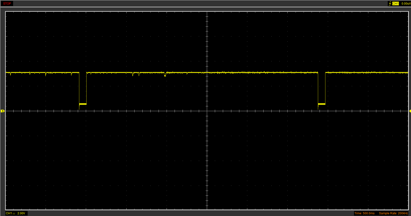
This is the resullt signal when connecting esp32 with pull-up resistor. Now it’s a piece of cake!
 Davide