0%
0%
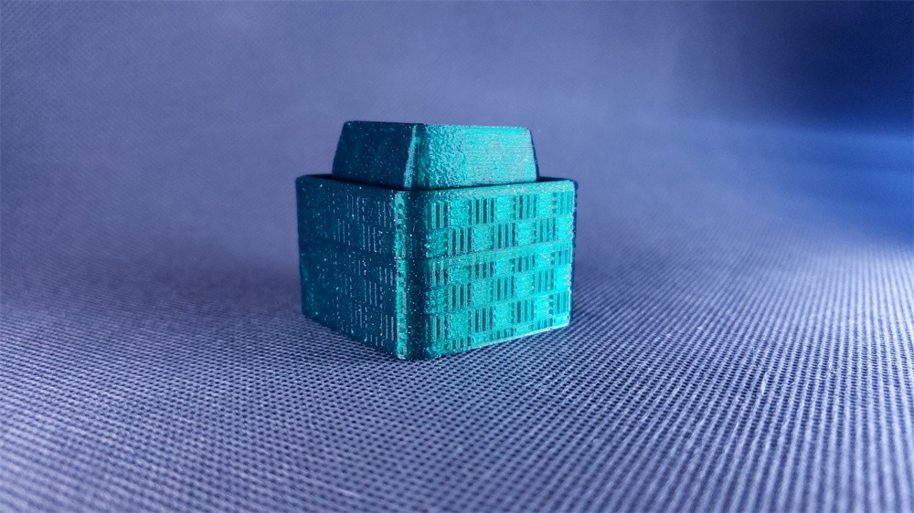
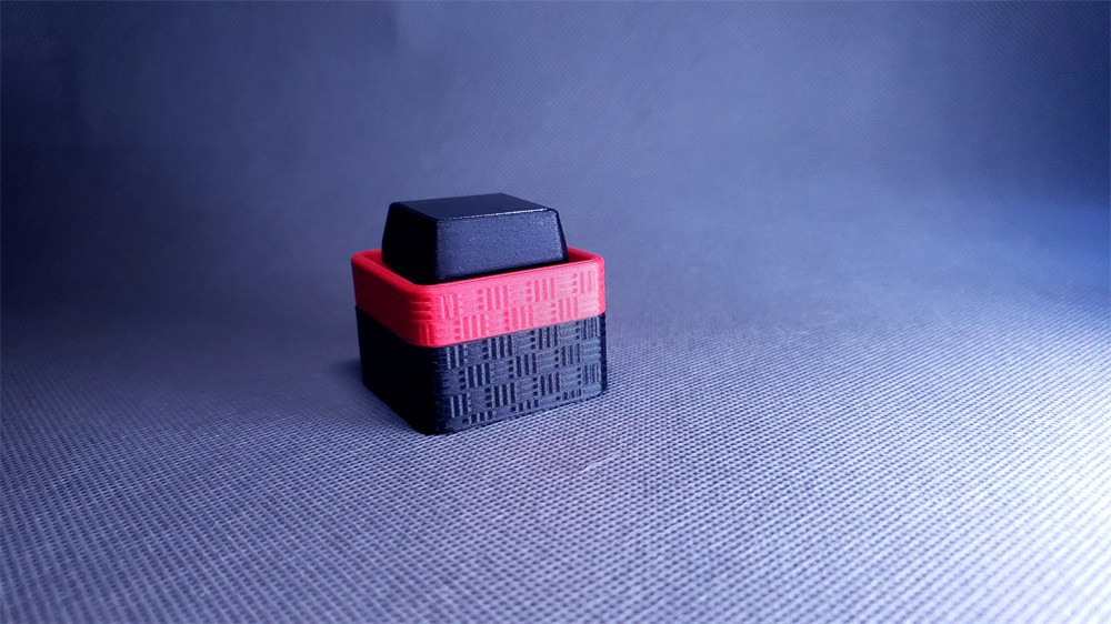
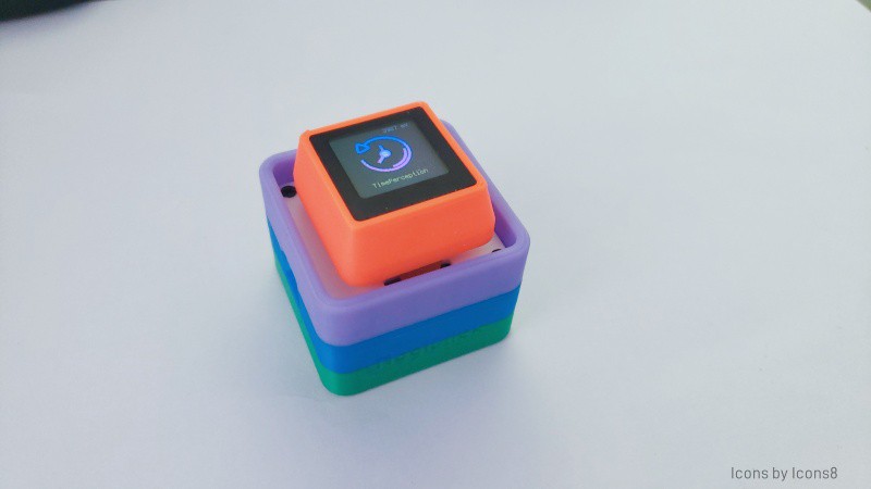
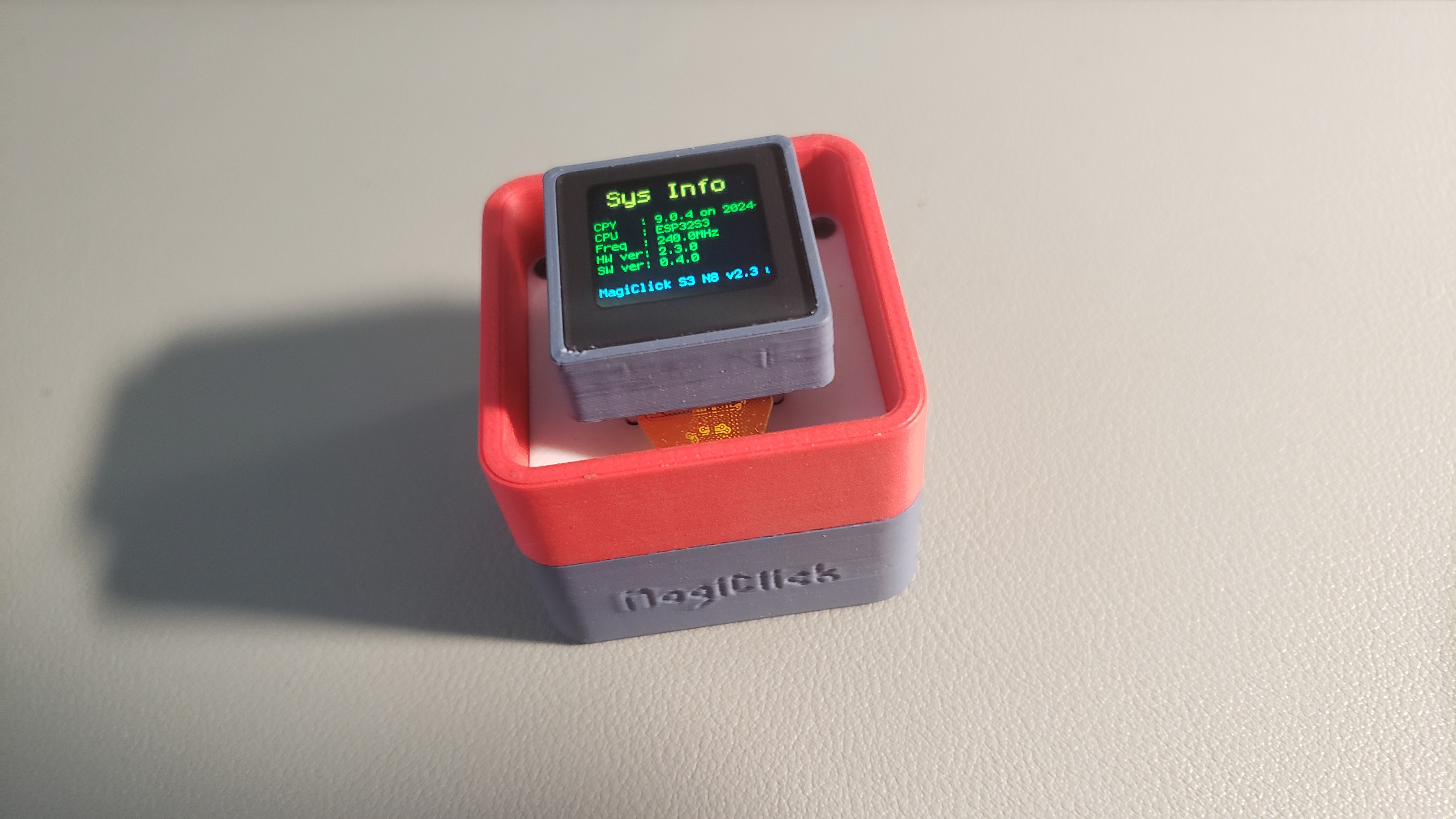
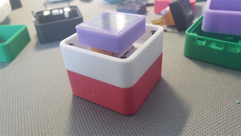
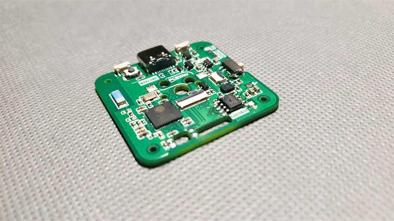
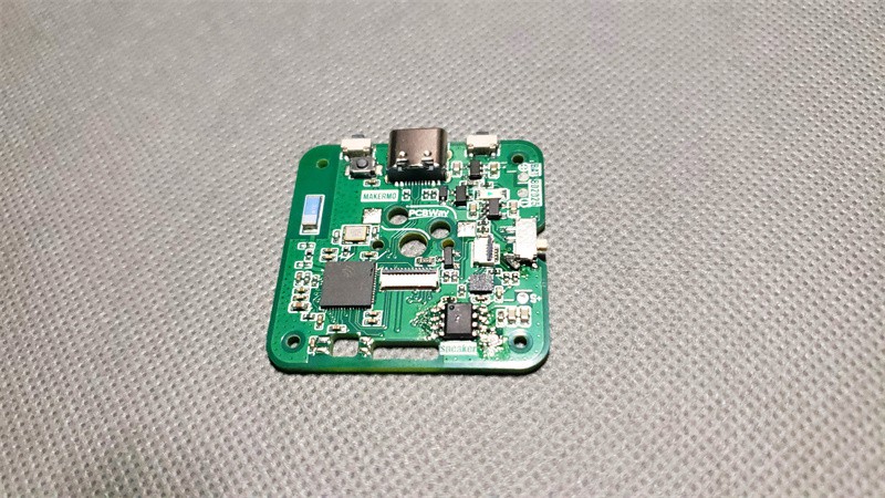
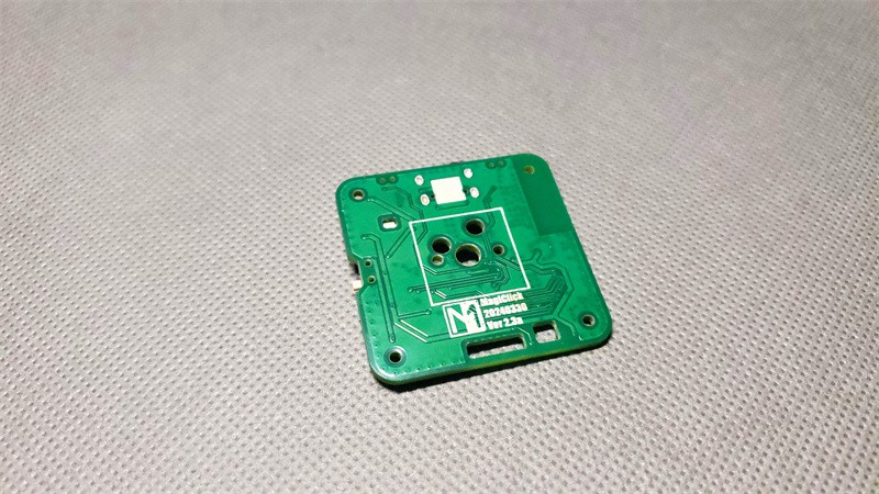
MagiClick S3 - Mechanical Macro Keyboard with Disp
A single-button keyboard, based on circuitpython
 MakerM0
Become a Hackaday.io member
Already have an account? Log in.
Just one more thing
To make the experience fit your profile, pick a username and tell us what interests you.
Pick an awesome username
hackaday.io/
Your profile's URL: hackaday.io/username. Max 25 alphanumeric characters.
Pick a few interests
Projects that share your interests
People that share your interests


 Stefan Köhler
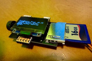
 microwavemont
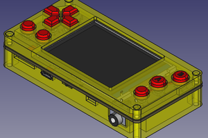
 Fuji Pebri
 Patrick Thomas