Challenge the project addresses:
Currently DIY robots have only one of movement possibilities:
a) Slow, but powerful - servos
b) fast but imprecise and requires tanks - pneumatic actuators.
c) slow and powerful but messy - hydraulic actuators
I want to add another option - very fast, precise and fully electric replacement for pneumatic actuators.
How the project will alleviate or solve the problem that the project addresses
By building fully open-source linear electromagnetic actuator with enough documentation that anyone with basic soldering skills can replicate.
How the project might be world changing
This project will add totally new option for robot builders.
Open-source licenses and permissions
This project does not use third party closed source components, only gnu stdc library (avr-gcc). Final working firmware and board schematics and gerbers will be open-sourced and documented.
How it works: actuator consists of tubular coil and neodymium magnet of atleast the same length. When polarization of coil is the same as of magnet, it is drawn inside coil. If polarization is opposite, magnet is forced out of coil.
Sensing of position:
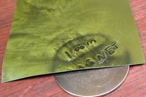
1. Cover coil and inside of plunger shield with aluminum foil and sense capacitance.
2. Sense inductance of coil.
3. Add resistive strip and check position with voltage.
4. Add optical linear encoder.
Case 1 is probably easiest on code but capacitance here is so small that just touching this actuator will change it. Case 2 is probably easier but requires that PWM is never 0% or 100%, because inductance is measured with change of current. Case 3 is easiest to measure by microcontroller but it is mechanically more demanding because one would need to incorporate resistive strip and wiper and make everything very rigid. Case 4 is less demanding of mechanical tolerances but doesn't give current position on startup and requires going to either extreme position.
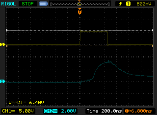
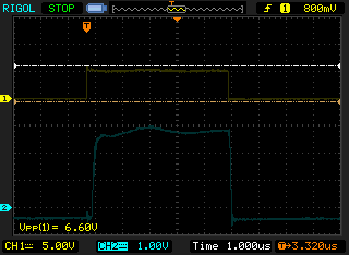
Typical forces:
With magnet 12mmx55mm and coil of inner diameter 14mm, outer 24mm, wire 0.4mm and voltage of 7V I've achieved about 5N of force but coil started to be warm to touch. According to my calculations current density was 7A/mm^2, where "safe" one is considered as 2,5A/mm^2. Better measurements of force will be taken in future after completing h-bridge.
Calculating coils:
I've cobbled together a spreadsheet to calculate some usable parameters of coils. Most important ones are "current x coils" which predicts relative force of a coil and "current per mm2" which predicts current density. Safe current density is 2.5A/mm^2 of copper wire, but for 10-20s it can go to 10A/mm^2 and more for shorter periods. Calculator gives good starting values for chosen coil size and you can tweak coil outside diameter until your calculated resistance is similar to your measured resistance. If your coil is perfectly aligned, measured and calulated resistance should be within 10%.


 DeepSOIC
 CapitanVeshdoki
 Jonathan Bruneau