-
Inductance measuring may yet work
03/20/2017 at 19:12 • 0 commentsThis weekend I've tested "proper" measuring of current, with resistor in series with coil. It's not yet working but atleast I've found that with inserted/retracted core there is difference of 5.35..5.5V (measured on sense resistor) in current min and max for pwm on and off times which should give me enough difference to actually measure position.
Bad news: progress will be slow for some time, my car got crashed and I don't have money for hobbies for some time, so no new pcb version for some time. Also when upper transistor is on, voltage on resistor is positive. When it is off, voltage is negative. measuring current means that there will be negative voltages or over-supply voltage on sensing resistor (physics, bitch!) so I will have to think some more on cheapest and simplest way of measuring this current. For now it would require generating negative voltages for comparators and chips which do this cost more than comparators themselves.
As always: if anyone has any ideas how to measure this beast, I would love to listen you.
-
First full test: inductance measuring won't cut it
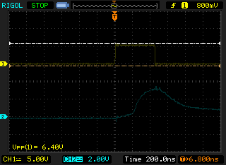
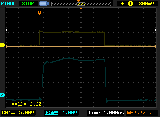
03/05/2017 at 20:19 • 0 commentsToday pcb was completed and tested. Unfortunately coil inductance almost doesn't change when inserting magnetic core. Driving coil like in buck converter also didn't work, voltage change is faster than my comparator bandwidth (full swing of voltage is 450ns, comparator output response is 300ns).
Some screenshots from oscilloscope, CH1 is pwm signal, CH2 is connected to pin3 of Q1 (high drive side of coil in this test):
![]()
![]()
My problem could be caused by measuring voltage on coil connections, not current through coil. But that would be only a problem when measuring inductance. The real problem: why that waveform on second screenshot doesn't change with inserted/removed core? It should change atleast a little, but it doesn't. Only during moving in/out, which is expected (induction).
If anyone sees an error here, comments are very welcome.
-
Pcb almost done.
02/26/2017 at 11:10 • 0 commentsPcb almost finished, but couldn't recover mosfets from old board also didn't have some elements, testing next week.
![]()
![]()
-
Pcb project finished
02/05/2017 at 16:59 • 0 commentsIt was probably the most complicated pcb I've designed so far and I'm glad I'm not doing it on a prototyping board. Comments what could be done better are very much appreciated. I will send it to fab this week.
This version allows to configure what drives upper transistors (pwm from MCU or output from comparators) and what sets reference voltage for comparators. This way I can switch this board between sensing edges by mcu and counting switching frequency when in comparator mode. Commanded position could be set on ANALOG_IN or via serial.
-
New idea - make dc-dc converter out of driving coil
02/04/2017 at 17:06 • 0 commentsHad an idea yesterday to drive coil like inductor in dc-dc converters or voltage choppers. Comparators would turn upper stage mosfets on and off to maintain desired voltage which could be set from MCU with pwm and lowpass filter. Inductance would be sensed by measuring switching frequency. This frequency would be about 10-100kHz. It's far less demanding on code and inputs. Even 8bit timers can drive it but it requires one timer/counter with external inputs (or external counter).
-
Updated scheme
01/31/2017 at 19:59 • 0 commentsScheme updated, will now allow detecting falling or rising edge of signal, will not burn when voltage of coil is bigger than 5V. This driver is now complicated enough that it requires full pcb. I will design it this week, but making will take time so expect next update in a month.
-
First try (partly) unsuccessfull
01/30/2017 at 18:48 • 0 commentsAfter whole weekend of making v1 on a prototype board and whole today of debugging, first try was unsuccessfull. I only had about 15min to test it, but it looks like at 1,5V rise time is about 10us and fall about 1us. I was measuring fall time and it's too fast to measure with atmega at 8MHz. Aditionally my comparator was biased too much and didn't even fire. More testing with better setting will follow next week. Until this time don't use my scheme as final reference.
Also - don't make such complicated projects on a bare prototyping board. At least use board with connected pads.
In such projects oscilloscope is indispensable for validating projects, in this instance 10mhz of bandwidth was absolute minimum.
-
Designed a driver
01/25/2017 at 20:32 • 0 commentsI've designed a h-bridge driver with atmega48 and irlz24n mosfets. LM393 comparator will be used to check inductance of coil. When voltage on coil drops to 0V after turning off voltage on upper bridge stage, MCU will check time and will be able to tell how fast it dropped. This will hopefully have enough resolution to get position in range 1-100. With 50mm length that means 0.5mm physical resolution. After weekend I will be testing this with oscilloscope.
Electromagnetic linear servo
Electromagnetic servo actuator for robots which will combine pneumatic speed and working principle with electronic control.