Creating AT for PRM: AnyAdapter (万接站)
Multifunctional retainer attachment platform designed for wheelchair users.
Multifunctional retainer attachment platform designed for wheelchair users.
To make the experience fit your profile, pick a username and tell us what interests you.
We found and based on your interests.
WechatIMG177.jpgJPEG Image - 3.23 MB - 05/17/2024 at 09:31 |
|
|
WechatIMG176.jpgJPEG Image - 2.85 MB - 05/17/2024 at 09:31 |
|
|
WechatIMG159.jpgJPEG Image - 2.26 MB - 05/17/2024 at 09:31 |
|
|
WechatIMG170.jpgJPEG Image - 3.57 MB - 05/17/2024 at 09:31 |
|
|
WechatIMG172.jpgJPEG Image - 1.85 MB - 05/17/2024 at 09:31 |
|
|
First Version
In the initial version of the case for the joystick and portable charger, I aimed to create a compact, dual-purpose design to be placed on a mini table attached to our project's base to address users' concerns about space limitations in hallways with this product. However, testing revealed that this setup was neither effective nor space-efficient, leading to increased clutter. The limited space of the case itself hindered joystick usage and mobility, prompting a reevaluation of the whole design. I also recognized the need for the portable charger to securely fit in its slot. Additionally, accommodating the joystick wiring became necessary. Upon reflection, I concluded that splitting the case into two parts and mounting it directly onto the motor would be the optimal solution.
Final Version
Joystick Case:
When designing the joystick case, I divided it into three parts: the main section housing the Arduino and joystick; a slideable top cover with a hole for joystick access; and a side door with a hole for sleek wiring integration. The main section featured screw holes and screws for secure mounting of the case on the motor and Arduino onto the case. Priority was placed on effectively housing the Arduino and joystick while ensuring joystick functionality. A screw-based design enhanced security, with the top cover requiring sliding into the main section before screwing into place, further reinforced by attaching the left side cover to both the main section and the top part. Notably, the joystick hole was made 5 mm larger than the joystick for full mobility; a hole matching the joystick size restricts movement.
Portable Battery Case:
When designing the portable battery case, the focus was on ensuring usability for individuals with reduced upper mobility, a common concern among wheelchair users. It was essential for the case to enable independent access to the battery without requiring assistance. User feedback underscored the importance of this feature, leading to the development of a design allowing easy insertion and removal of the portable battery using any joint, with a sliding cover securing it in place through the top slit. Similar to the joystick case, this one was also screwable onto the motor for added security. Positioned on the right side of the motor for convenient access, it met users' preference for quick and independent battery access. In contrast, the joystick case, placed on the left side, didn't require constant visibility or immediate access, as the joystick operation was familiar and less physically demanding for wheelchair users as many wheelchairs use joysticks.
Final Version Printed And Modifications(If Any) Made
Joystick Case:
To See Joystick Case In Use Click Here
No modifications were made to the design, but in the future, I would consider incorporating a feature to completely conceal the wires from the user within this case.
Portable Charger Case:
To See The Portable Charger Case In Use Click Here
I eliminated the sliding cover originally intended for top installation and securing of the portable charger, as testing revealed its usability challenges as it was difficult to use even for someone without any upper mobility issues. Instead, I tightened the hole for the portable charger with a rubber-like material to securely grip the portable charger while still allowing easy removal with the user's joints. Given more time, I would consider incorporating a buttonable buckle with holes(to allow usage of the ports) to further secure the portable charger from the side.
Everything Together:
To See The Final Product Altogether Click Here
Click here ⬇️
First base version:
Installation and tests:
Worked well! There is a literature and art that since there is only one screw hole at the bottom, there will be a problem of base rotation when installing heavy objects on it.
However, I am also trying to explore a more effective and beautiful Base design. The cylindrical Base is indeed interesting, but when the Adapter is connected to it, there is not enough contact surface. This will cause the service life of the inserts to be greatly reduced, because all the stress support falls on the inserts. It would be much better if there were other contact surfaces to assist. So I redesigned the eight-sided version and the six-sided version. When designing the eight-sided version, I came up with a new idea. Users will basically not install multiple devices on the base at the same time, so it is actually not necessary to design too many layers of inserts. A better designer would design just one row and then add a telescopic rod underneath it, which would add even more possibilities.
Printed by 3D printers.
Final look:
Users and I really like this white and gold colorway.
In the next two versions of the base, I increased the number of screw holes on the bottom, and after installing more small screws, the problem of base rotation was solved.
In our previous work with Siyi and Michener, I have been working hard to explore more commonly used connection methods. When I was doing market research early in the morning, I discovered that there were already many accessories for electronic device stands on the market, and they were all technically very mature. However, these accessories are all designed for bicycles or other items, and there are absolutely no such accessories designed for wheelchairs. So we hope to fill this gap. The most critical point in filling this gap lies in the connection method with the wheelchair. However, this is a very big challenge. In market research, we found that every wheelchair is different, even hugely different. It is very difficult to design a universal connection method, which may be why there are no such products for wheelchairs. If you want to achieve universal adaptability, you must develop based on the common points of wheelchairs.
Therefore, I obtained a lot of information from our three Co-Designers about the wheelchairs they use, and also researched a large number of widely used wheelchairs from the market. Finally, through a long period of comparison, I found that no matter how different they are in appearance, they will always have two things in common: the wheelchair armrests and the support structure of the front wheels or pedals.
So, how to rationally utilize and combine these two parts?
I got very important inspiration from setting up selfie sticks for Michener and Siyi, and I also discovered a very useful structure, which is the double-head clip. This kind of double-head clamp designed for bicycles can set up the platform we want between the two parts. Considering the location of our project, I combined them with telescopic poles to create a platform to place our project. In fact, we can also use only a double-headed clamp to set up, but in previous practice, we felt the stability of the triangle. One double-head clamp is not enough, but two will make the entire structure more stable and reduce sway in at least one direction.
The next step is to design the platform. The simplest way is to install a board on top, and then embed two inserts in it to connect with the telescopic rods supported below. But I soon realized a potential pain point: since everyone's wheelchair is different, even with two double-headed clamps like that, it is difficult to ensure a certain distance between the two telescopic rods. Therefore, I designed a slide rail structure built into the platform. I took inspiration from the design of double-head clamps and designed the slide rails to be able to control mobility by turning screws. After loosening the screws, the two inserts in the slide rail can move freely and adjust the distance. After tightening the screws, the two inserts can be fixed.
In this way, a more universally applicable installation method is completed. We have conducted multiple rounds of testing and have received positive reviews from users.
The initial connection we envisioned was a clamp to attach the entire project to the armrest of the wheelchair. When I first started designing the clamp structure, I thought it would be a simple task. However, once I actually started working on it, I found that it was more difficult than I thought. It would be almost impossible for me to start designing a completely new clamp from scratch because I don't have the ability to machine metal or plastic parts. If 3D printing is used, there may be a problem of damage due to force, because the force on the clamp is actually very large, but there are precision parts such as large screws. So after trying out the design a few times, I converted my current one to: identifying a good enough clamp and finding a way to organically integrate our project with it.
Therefore, I purchased three different clamps and tested their possibilities individually.
To be honest, all three are pretty silly, but these are the most typical clamps I can buy on the market and the ones that worked best for our project. The one I originally bought was the one in the middle. It has a simple structure and can be easily combined with some wooden boards and other things. However, the clamping part is too short to function as a clamp. Even though there are several screw holes on the top of the clip, I still had trouble finding a suitable way to extend it. Even when extended, its stability was very questionable, so I quickly ditched the clamp. The second clamp is the one on the far left in the picture. It's more classic and more stable than the first clamp, but it has nothing to expand on to create an organic connection to our project. In addition to this, this model of clamp cannot create a large enough opening, making it unusable for some thicker handrails.
Finally I came to this clamp on the far right, which is my final design. This clamp is actually a clamp inside a mobile phone holder, which I separated out for use in our project. Although larger than the previous two, it is more beautiful and easier to adjust. Any user can adjust the clamp by turning the lower handle with very little effort. In addition, this clamp has holes in three different directions for connection. Although it was very difficult to exploit these three holes, I eventually figured out a suitable method with the insights from Freddie.
Initially I only used one of the connections, which resulted in the entire link being very unstable and shaking violently. Later, I purchased long cylindrical nuts, combined with long screws, a large number of nuts and corner codes, and successfully completed a relatively perfect connection.
After completing the clamp connection, we contacted Michener and tested our clamp structure on his wheelchair. The effect was surprisingly good, but Michener also gave us some valuable feedback, which will be mentioned in the next update.
After making and installing a selfie stick for Michener last time, we met a new friend, Siyi. She is also a wheelchair user and has a long history with our school. Five years ago, she came to NYU Shanghai to attend an event. During this event, she expressed her wish to have a fixed selfie stick to allow her to record her life. However, due to limited technology and experience, the students at that time failed to make a useful shooting pole.
After absorbing the experience from the last time, we quickly completed the assembly and erection of the shooting pole. However, during testing, we discovered some problems. The main problem is the severe shaking. After making many improvements, we realized that this was not a problem that could be solved with our existing technology, because the severe shaking came from the vibration of the wheelchair itself. Siyi's wheelchair is different from Michener and Emma (our other co-designer) in that her wheelchair has very small front wheels and does not have any shock absorption function. The wheelchair's tires are of poor quality and are worn, and there are also some issues with the tire's braking. This causes the wheelchair to vibrate greatly when starting, accelerating, and braking. In addition, due to Siyi's own physiological problems, her limbs will move violently involuntarily, causing more vibrations to the wheelchair. The ideal solution is to install a mature gimbal to eliminate all vibrations. However, purchasing a gimbal is too expensive, and making one yourself requires too much work. We ultimately opted to reinforce the brackets further. To our surprise, although the phone was visually shaking heavily on the stand, the shaking in the final video was almost negligible. Therefore, we finally succeeded in getting Siyi to use the available bracket.
Siyi's mother said: "It's really great. Siyi is really happy. Because this is a dream she has always had. She has been thinking about it for several years and now it has finally come true." Siyi said: "Now I feel finally free. I can take pictures of my own experiences!” Their feedback made me feel very rewarded. I can’t say that we successfully realized other people’s dreams with our designs, but I’m glad that we were able to actually help them and improve their lives. Their smiles are what keeps us moving forward.
*Freddie Testing with Siyi
While we were designing our project, we worked with some wheelchair users (who were also our future clients!) to design and install selfie sticks for filming.
Our first friend was Michener, who wanted us to help him set up a selfie stick on his wheelchair to record some of his travels. Michener also purchased a selfie stick himself, which saved us a lot of work. All we need to consider is how to install it on the wheelchair and how to make it as stable as possible and reduce vibration and shaking. I soon realized that this was a perfect opportunity to explore and experiment with a variety of mounting options and test their stability.
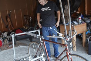
We tried out a selfie stick that Michener purchased himself. This is actually a selfie stick for bicycles. I found that there are many such designs for bicycles, and they are very mature, but there are extremely few for wheelchairs - this is the direction and reason for our efforts. We need to find a place on the wheelchair that is very similar to the crossbar of a bicycle to install the double-ended clamp. After testing several locations, including the armrests, we determined the best fit—the roller supports under the wheelchair near the legs. The roller support is a perfect metal rod, suitable for the installation of the double-head clamp; at the same time, it is relatively low and will not cause any inconvenience to the user. However, due to engineering reasons. No matter how tight we install it, there will always be some amount of wobble. Also, the stick provided with this selfie stick is too long. Even though it's adjustable, it's still at an embarrassing height.
We tried out some of our own accessories and in the process realized the importance of trying out the same screw model (luckily we used camera-specific screws from the beginning, which saved us a lot of trouble in purchasing and installation) . After some experimentation we successfully assumed the shooting pole. After testing, we found that there was significant shaking. I used multiple disposable straps for reinforcement and ended up with dramatic results. The last few attempts at shooting were very successful, with stable and clear footage.
Postscript
Michener loves this selfie stick. After installing a selfie stick, he began to frequently take photos and document his life. This is not only his driving recorder, but also his life recorder. He developed a new hobby, which is to turn on photography every time he travels to record interesting moments. After editing the video, he posted it online so that more people could see the world of wheelchair users.
Development Journal 1
After modeling and preliminary prototyping of our design we held a small demonstration at Microsoft. We got some very valuable feedback during this presentation, especially from an engineering perspective. We discovered a possible user problem: the user may not have enough ability to adjust the robotic arm. In the past design process, we took into account the poor mobility of the upper limbs that wheelchair users may have, and therefore specially designed the way for users to install the adapter. However, if our past design is used, the user may not have enough strength to adjust the adapter's position. If the adapter is designed to be extremely easy to adjust, its stability will be reduced. So here comes a problem.
Our mentor had previously mentioned whether we should consider installing a motor at the connection to make it electric, and we retained this suggestion at the time. Now, in order to solve the problem of users adjusting the position of the adapter base, we have officially decided to change our Adapter base to a robotic arm form.
In order to reduce the pressure of design and construction, we decided to use some parts and components of universal robotic arms to build the robotic arm, but in the later stage, we used appropriate methods to shield it to avoid exposure of the metal structure. We added the circular motion of the adapter base in the horizontal direction and the circular motion of the joint into the category of the robotic arm. We made new sketches for the new design. In addition, we referenced and selected some general-purpose robotic arms to build some movable prototypes to test the feasibility.
In terms of material selection, we tried to use Arduino accessories provided by IMA studios to build, but we found that they were not suitable for our project, either from functional or aesthetic considerations. We decided to purchase some existing robotic arms, test their performance and learn their movement patterns, and finally incorporate them into our design.
https://drive.google.com/file/d/1wk5S075zK4KK7bGrQCoCO1rIJTV7voBi/view?usp=sharing
Create an account to leave a comment. Already have an account? Log In.
Become a member to follow this project and never miss any updates

 Kate Reed
 In young Jang
 Joseph Prosnitz
 Shushanik Khachaturian