Fabian
-
Sunchronizer Update: S2 and D2 Are Here
03/26/2026 at 11:33 • 0 commentsQuick project update: after the first generation (S1/D1), I now have the 2nd generation variants ready and running:
- S2: single-axis (elevation)
- D2: dual-axis (elevation + azimuth)
Both versions are 3D-printable, ESPHome-based, and built for practical real-world use, not just bench demos.
S2 is the lower-complexity option with solid gains over static mounting. D2 adds azimuth tracking and is the best-performing variant for maximum daily yield.
I’m also publishing regular measurement series and analysis reports from real operation. The short version of the results so far:
- D2 yields about +12% compared to S2 (single-axis)
- both trackers massively outperform static orientation
- in one representative comparison, the tracker setup reached up to +144% vs static east/west references (time-window dependent)
Measurement overview and linked daily reports: https://github.com/Nerdiyde/Sunchronizer/blob/main/docu/measurements/MEASUREMENT_OVERVIEW.md
If there’s interest, I can post a follow-up with a direct S2 vs D2 build comparison (mechanics, BOM differences, and recommended setup path).
If you want to support me by building one: The STL files are available to buy here:- Sunchronizer S2 (Printables): https://www.printables.com/model/1574048-sunchronizer-s2-400w-module-solartracker-for-eleva
- Sunchronizer S2 (Cults): https://cults3d.com/de/modell-3d/gadget/sunchronizer-s2-400w-module-solartracker-for-elevation-axis-by-nerdiy-de-new
- Sunchronizer D2 (Printables): https://www.printables.com/model/1574049-sunchronizer-d2-400w-module-solartracker-for-eleva
- Sunchronizer D2 (Cults): https://cults3d.com/de/modell-3d/gadget/sunchronizer-d2-400w-module-solartracker-for-elevation-azimuth-axis-by-nerdi
-
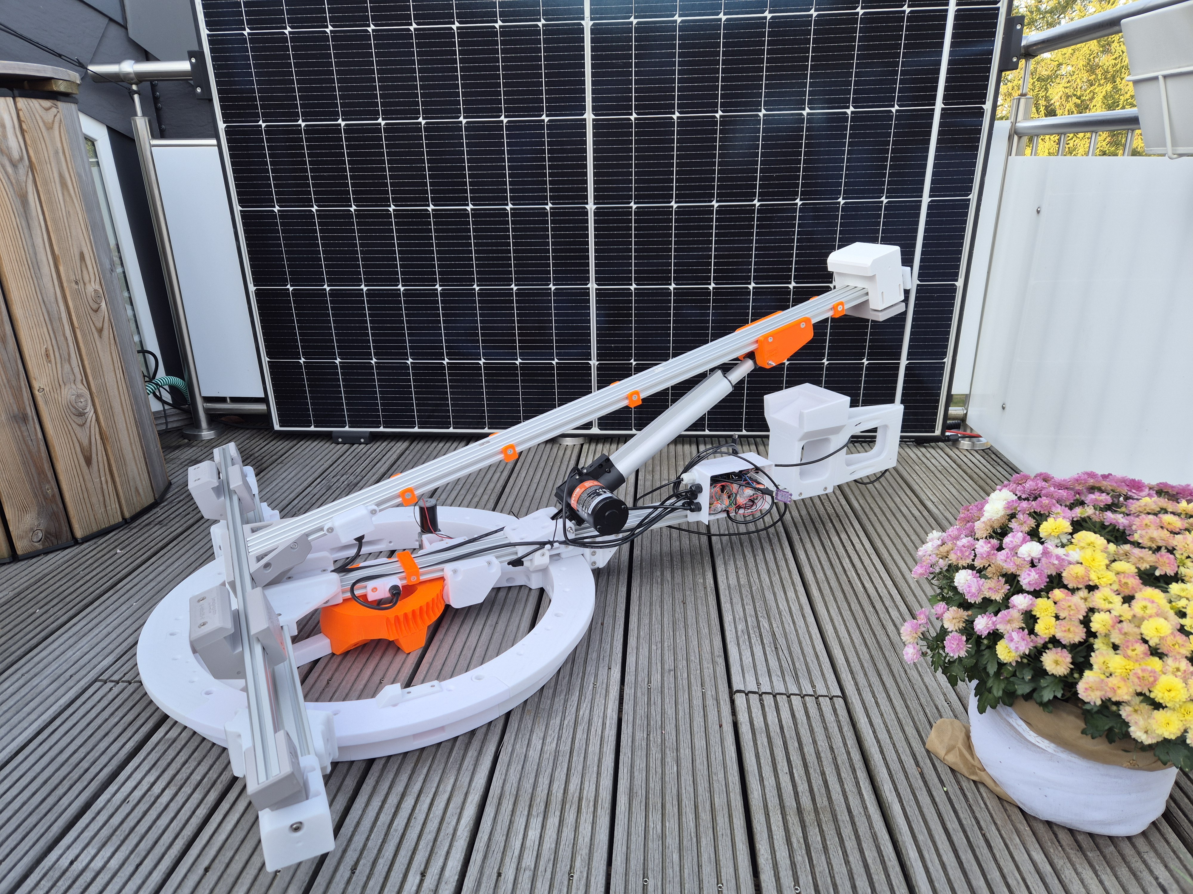
Dual Axis prototype installed
10/12/2024 at 19:19 • 0 commentsToday I installed the current prototype of the dual axis system. It's absed on the single axis version which is mounted on a kind of turret.
The possible rotation angle is about 205°. This range is limited by two endstop switches and for the worst case there is also a mechanical block.
The current azimuth angle is measured via a compass module on the controller PCB.
I will show some more details on the following pictures.
![]()
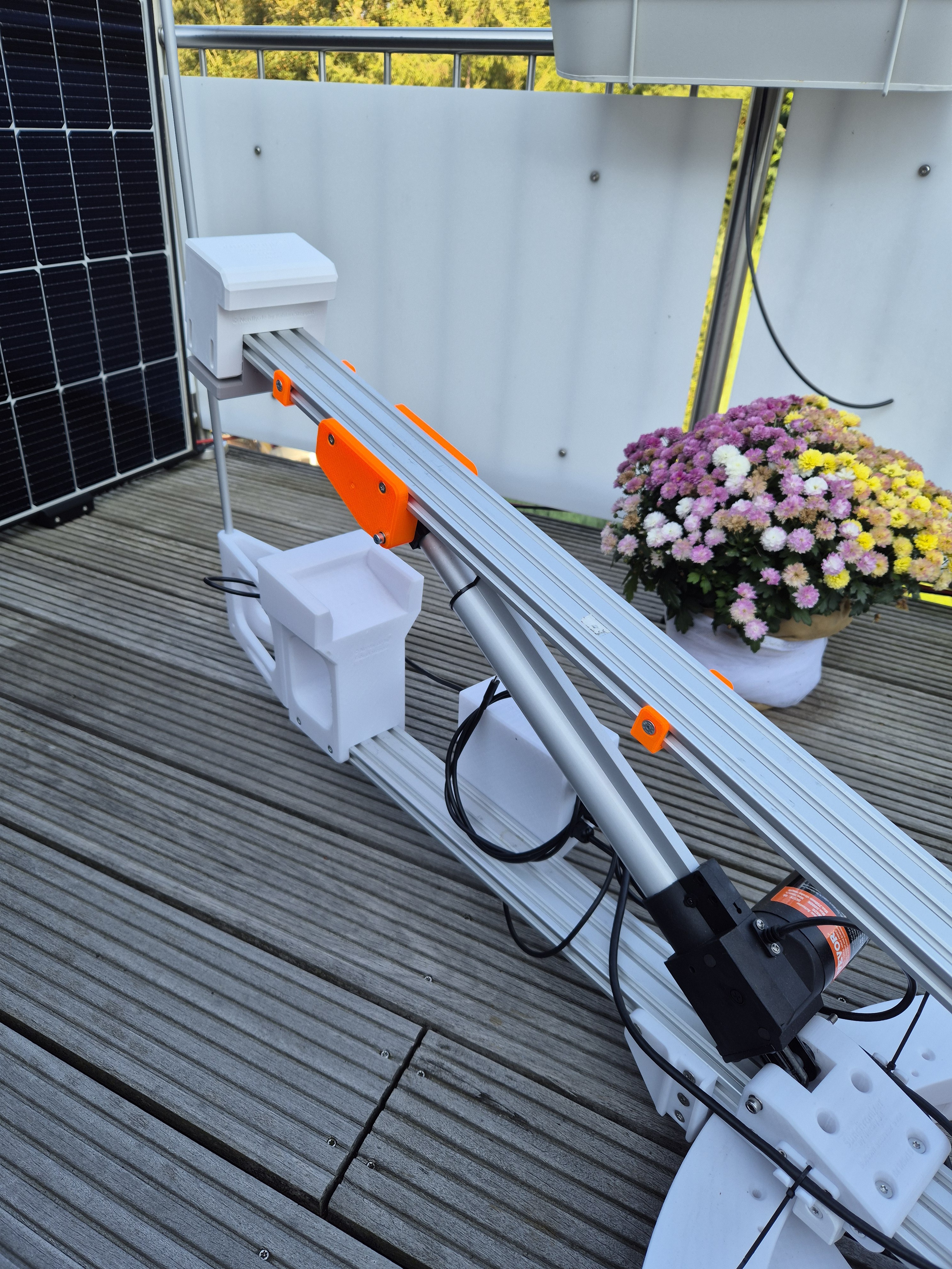
The Dual Axis version is basically the elevation (single) axis version extended by a turret. I used Prusament PETG for all 3D printed parts ![]()
On this picture you can see the initial version of the two endstops to limit the rotation angle. If one of these endstops is triggered the movement of the rotation axis is stopped. Unfortunately these endstops were not stable enough. Therefore I switched to bigger endstops. ![]()
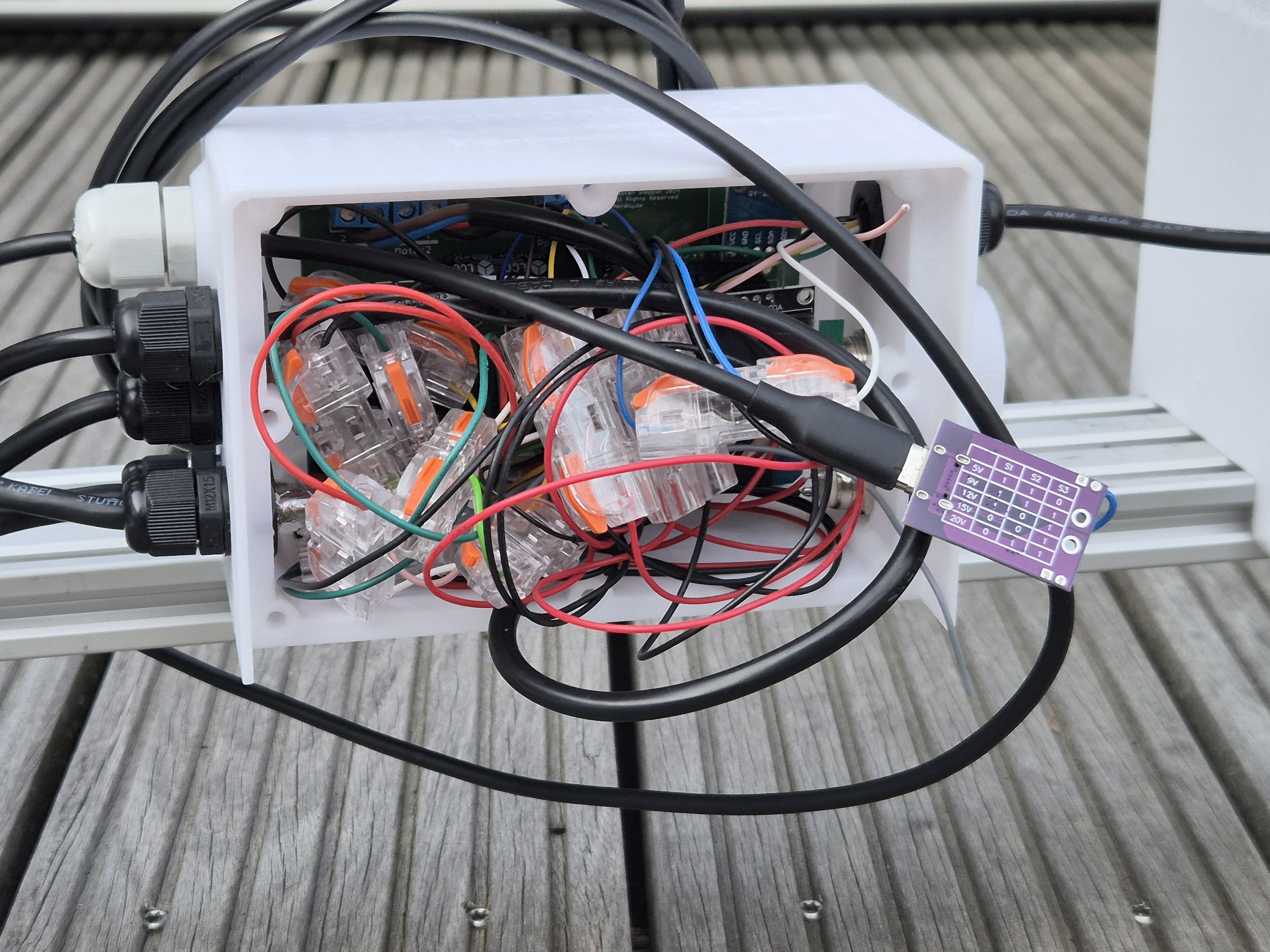
This was the test stage of the electronics PCB. Initially I tested all the connections with clamp connectors. Later I replaced them by properly soldered connections. The PCB is mounted splash waterproof in the 3D printed housing. The lid is made of a lasercut acrylic glas part. ![]()
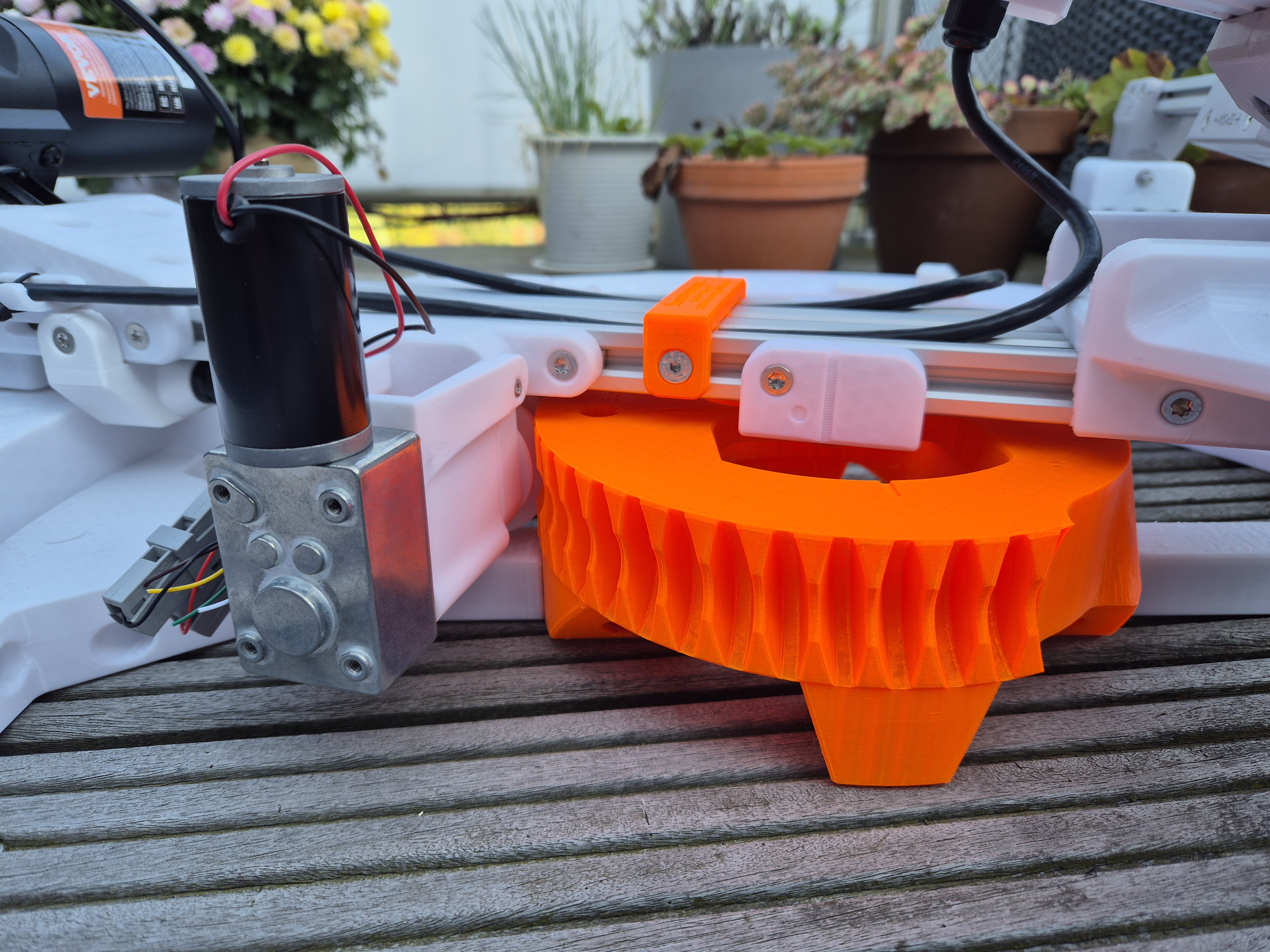
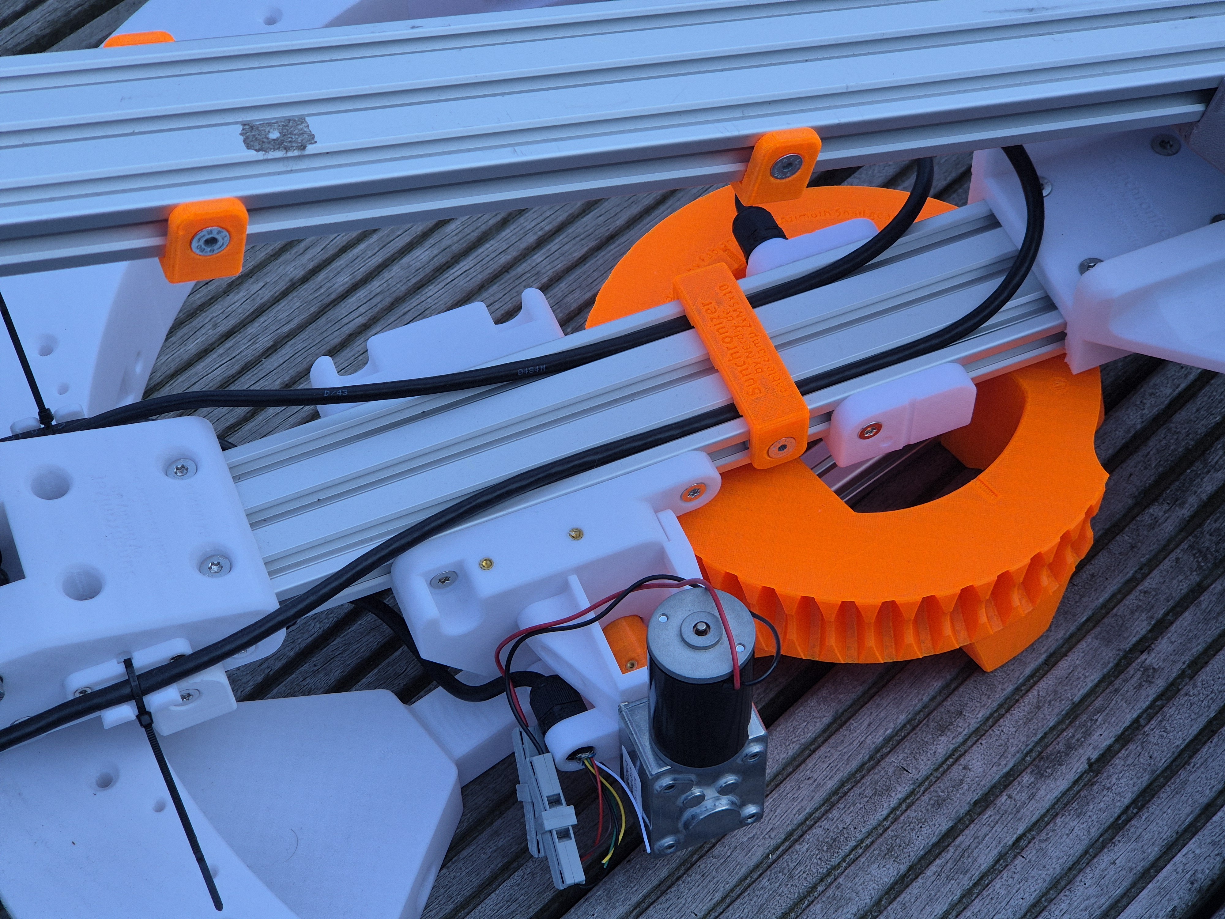
View on the snail gear that is responsible for the azimuth angle control. ![]()
![]()
-
Dual Axis support incoming
07/24/2024 at 17:19 • 2 commentsJust a tiny sneak peak on what I'm working right now.
Since the first prototype of the single axis tracker is doing his longterm testing job I'm silently working on the dual axis support.
The current plan is to mount the single axis assembly on some kind of turret which can be rotated with a snail drive and a 12V gear motor.
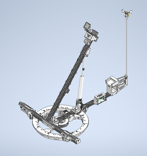
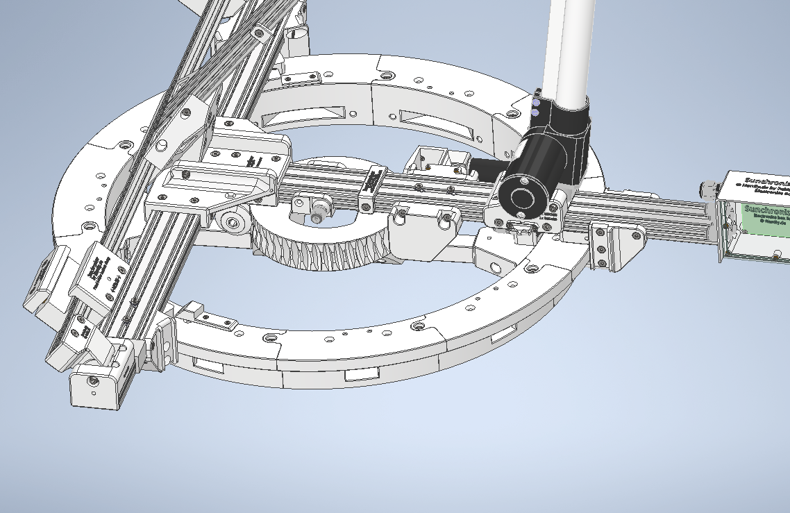
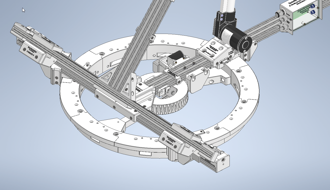
I hope the pictures give an idea about the construction.
![]()
![]()
![]()
-
SolSpot - A universal light sensor for solar tracker setups
04/24/2024 at 17:10 • 0 commentsOne thing is critical for proper and fast Solar Tracking: Measure the current lighting conditions. Therefore I designed my own Solar Tracking Sensor called "SolSpot" which you can see below.
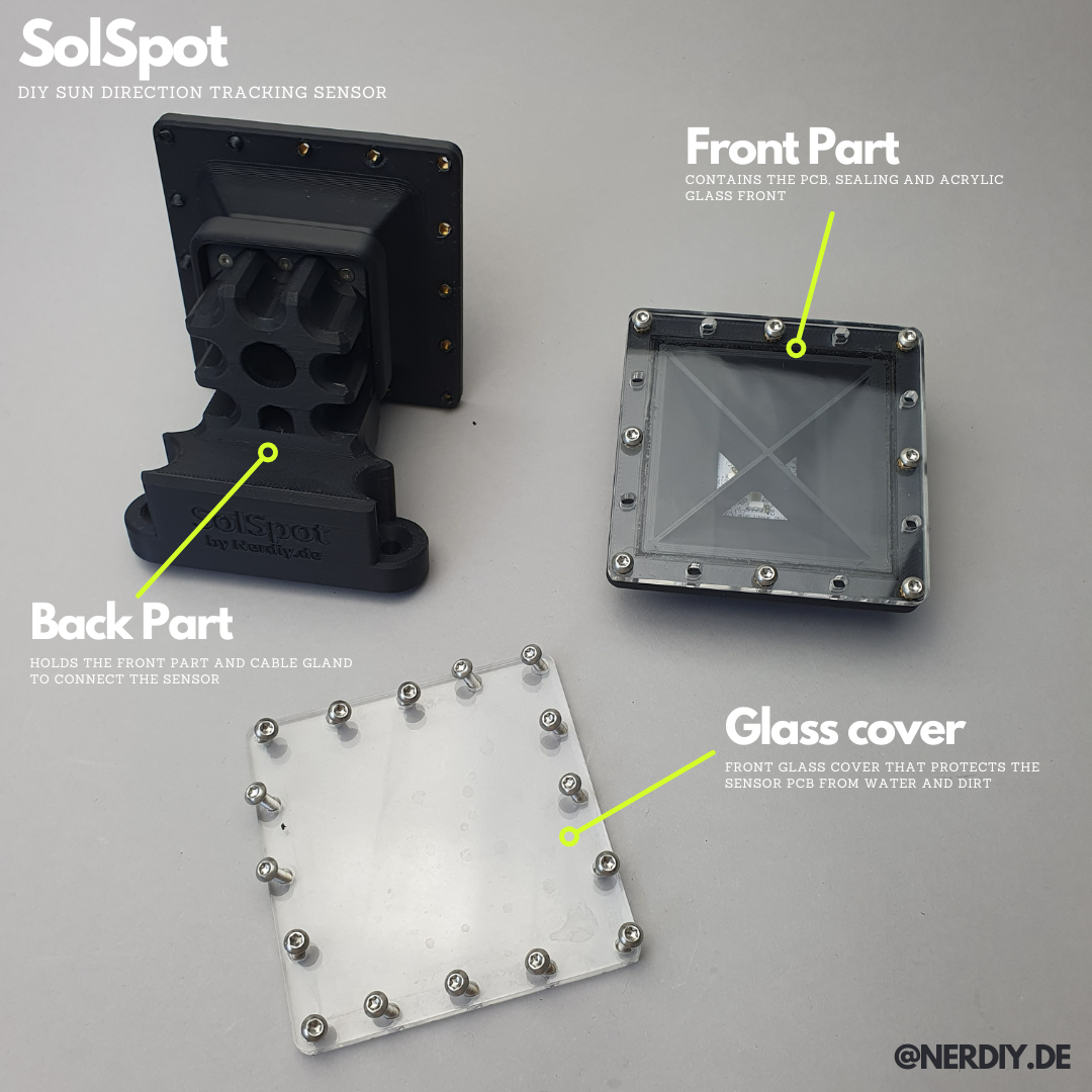
Below you can see my (current) finale state of the SolSpot housing. In order to connect the individual components together in a (hopefully) waterproof manner, I use a sealing ring printed from TPU. This is inserted into the grooves provided and clamped between the components. The watertightness of the front panel was particularly important to me because the sensor electronics are located directly behind it.
![]()
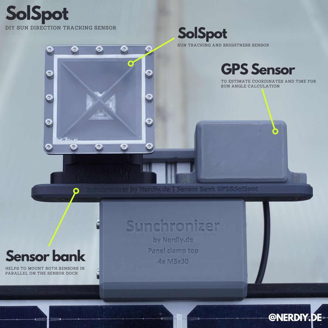
CloseUp of a mounted SolSpot and GPS Sensor on the Sensor Dock on top of the Sunrchonizer prototype. So that both sensors can be mount in parallel the Sensor Bank is used as adapter plate. ![]()
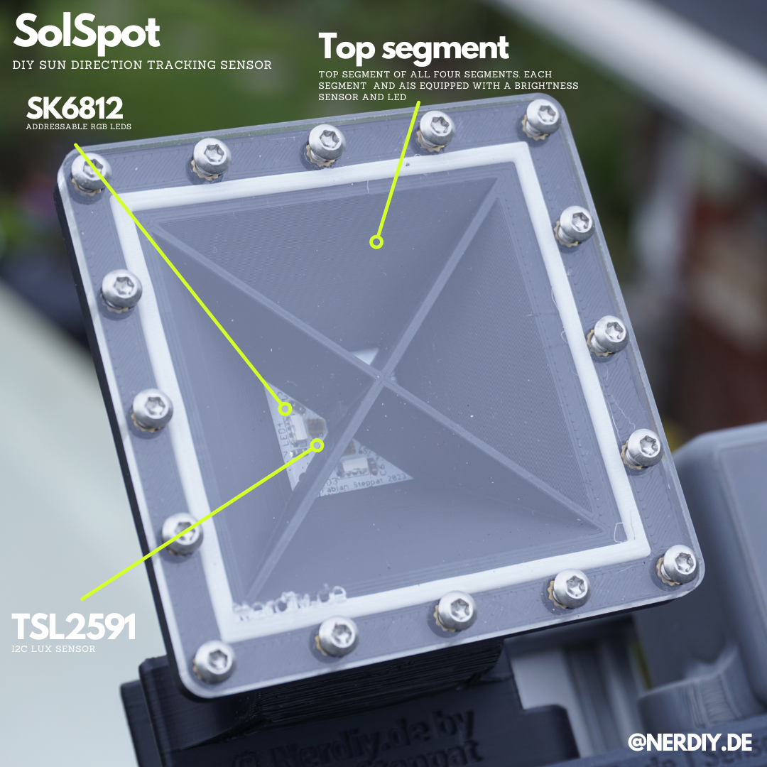
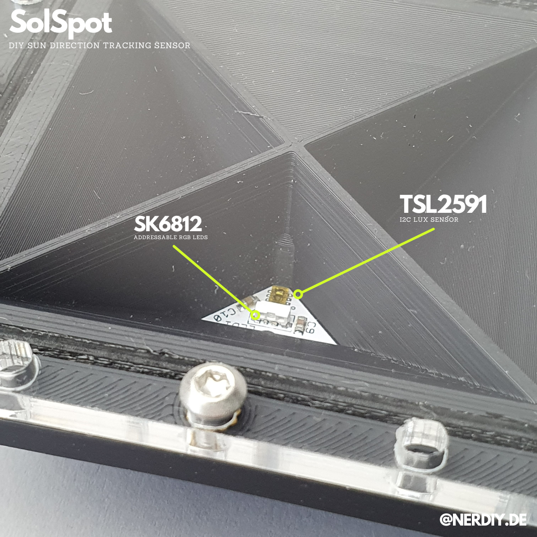
CloseUp of the SolSpot sensor. The LED and brightness sensor per segment is visible. ![]()
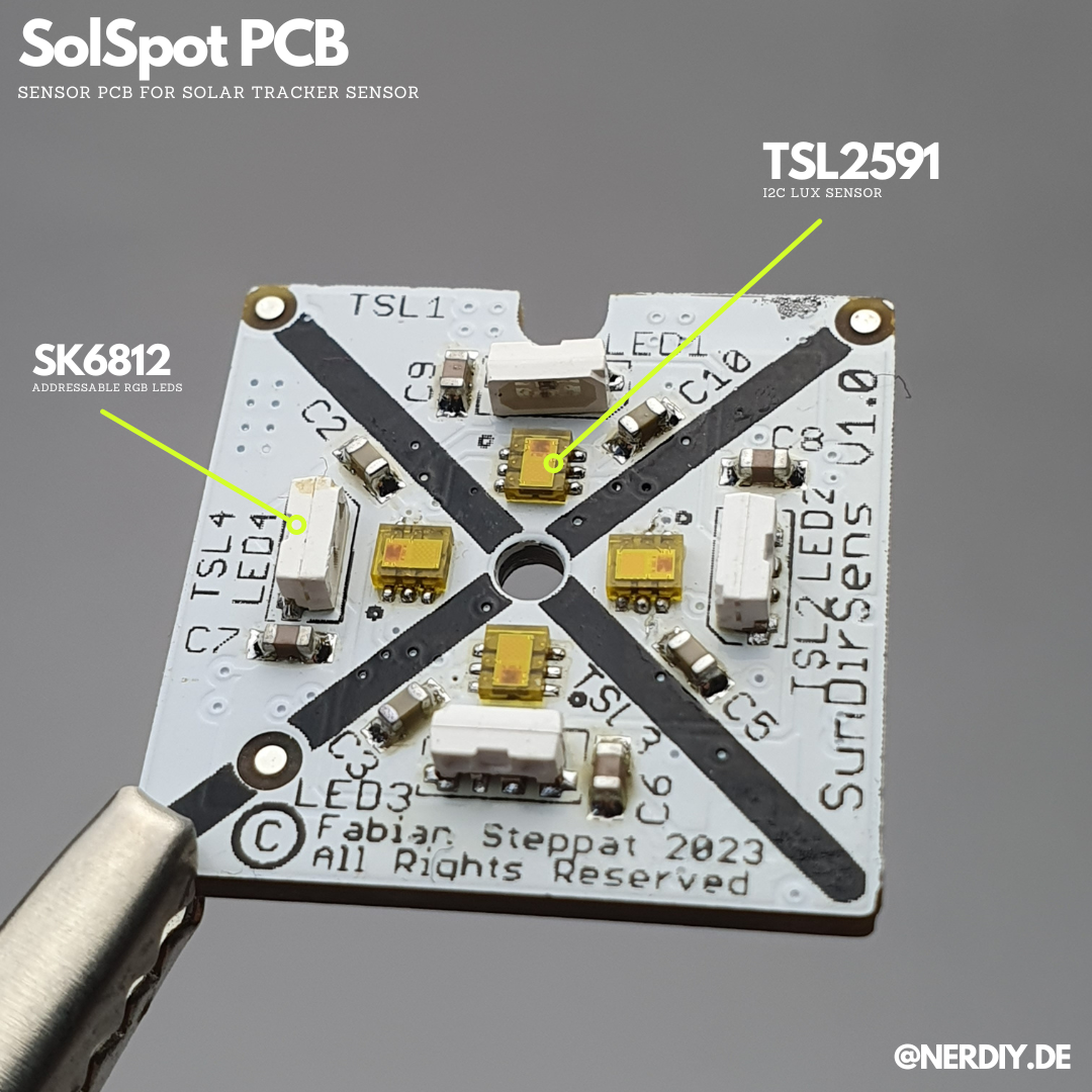
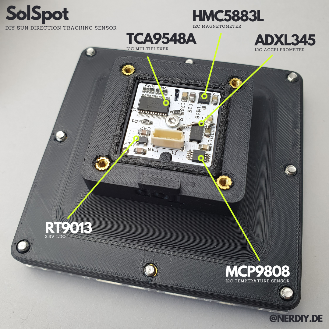
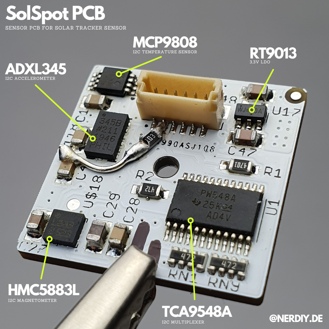
Below you can see a picture of the circuit board installed in the SolSpot Housing. Four TSL2591 light sensors are installed on it, with which the brightness in the respective sensor element and thus the alignment/direction of the sun can be measured by comparing the brightness in the different segments. Next to each light sensor I also installed an SK6812 Side LED. This allows the sensor to carry out a simple functional test (for example at night) to ensure that the light sensors are still working correctly. Many thanks to pcbway.com for assistance with this project by providing their PCB service.
For the light sensors I use a TSL2591. These are read out via the I2C bus. Unfortunately, these do not have an adjustable I2C address. That's why I read the individual sensors via a TCA9548 I2C multiplexer. With this IC, an I2C bus can be multiplexed to eight different buses. Additionally an ADXL345 acceleration sensor and a compass are also installed.
![]()
Top side of the SolSpot PCB. Bottom side is available below. ![]()
Close Up of one of the segments of SolSpot containing a TSL2591 brightness sensor and a SK6812 Side LED. ![]()
Protype view of the mounted SolSpot PCB in the Front part of the SolSpot Housing. The PCB is fixed by an M2 screw and (hopefully) protected by humidity via a TPU based sealing "ring". ![]()
Bottom side of the SolSpot PCB. Including a little whoopsie (missing reset pull-up) that I fixed manually. -
Electronics in detail
04/22/2024 at 19:10 • 0 commentsThe current controller in the first Sunchronizer prototype is based on a prototyped schematic on a breadboard.
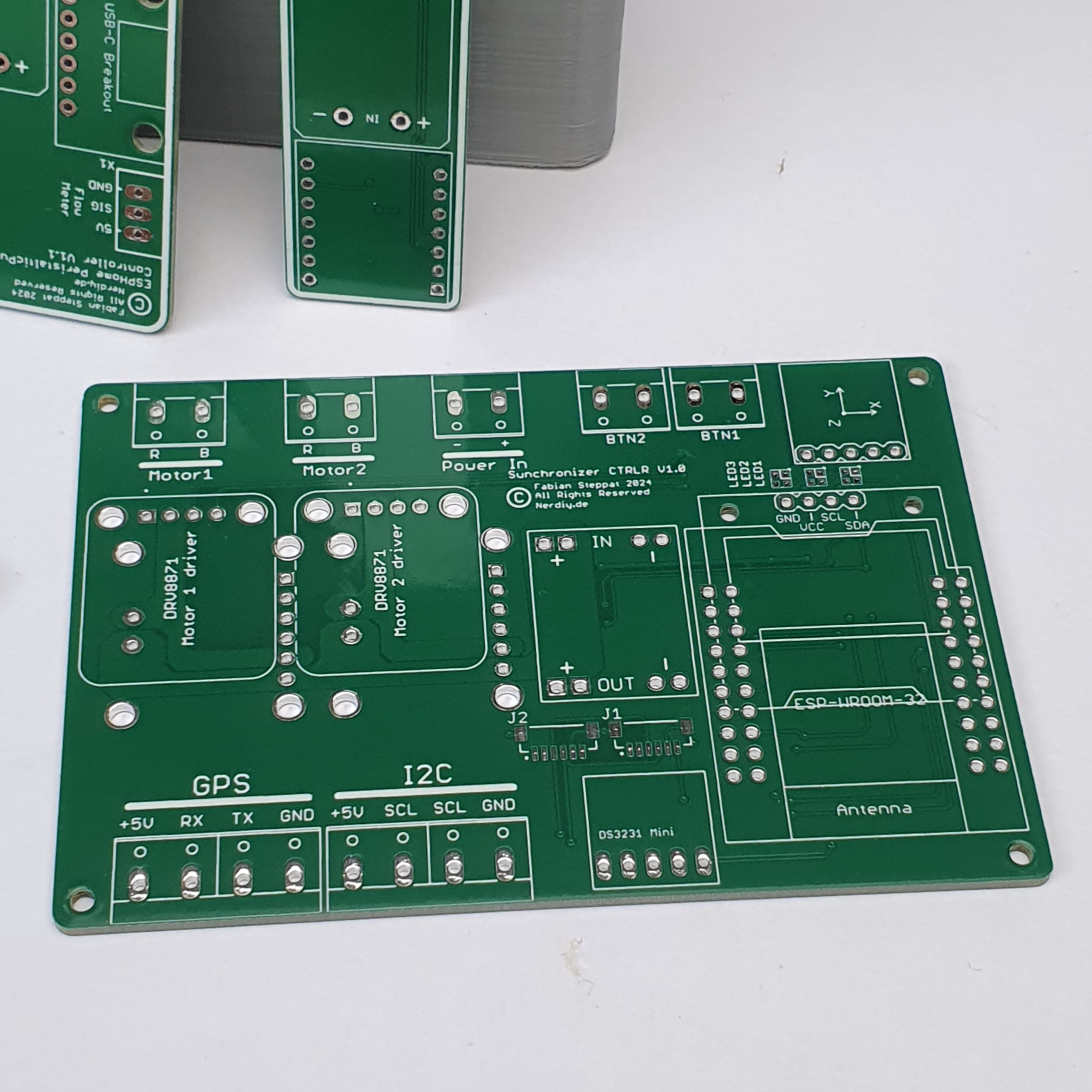
Below you can see my first approach to bring this approach to a ore professional level which is supported by the guys at pcbway.com. Thanks to them I have the chance to bring my virtual design within a few days to a real working PCB.
The controller will be based on an ESP32 MCU which reads the acceleration signals from the BMI160 via I2C Bus. Additionally the GPS sensor can be connected via serial connection.
With the PCB there is also the option to connect an OLED display, a compass module, a RTC, a SolSpot Sensor and an Anemosens wind sensor.
As motor driver a DRV8871 is used which will/must be replaced later by a bit more powerful one. This is needed because at the beginning of the lift movement the linear actuator pulls slightly more current than the max allowed 3A (of the DRV8871).
![]()
-
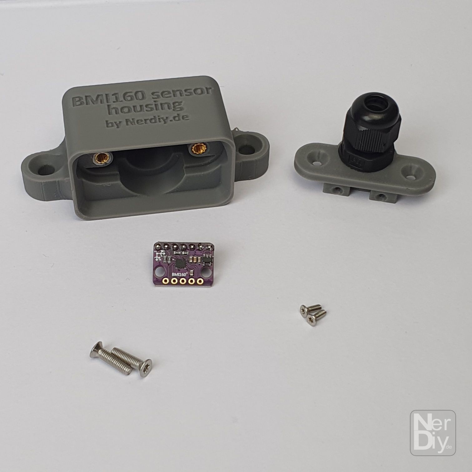
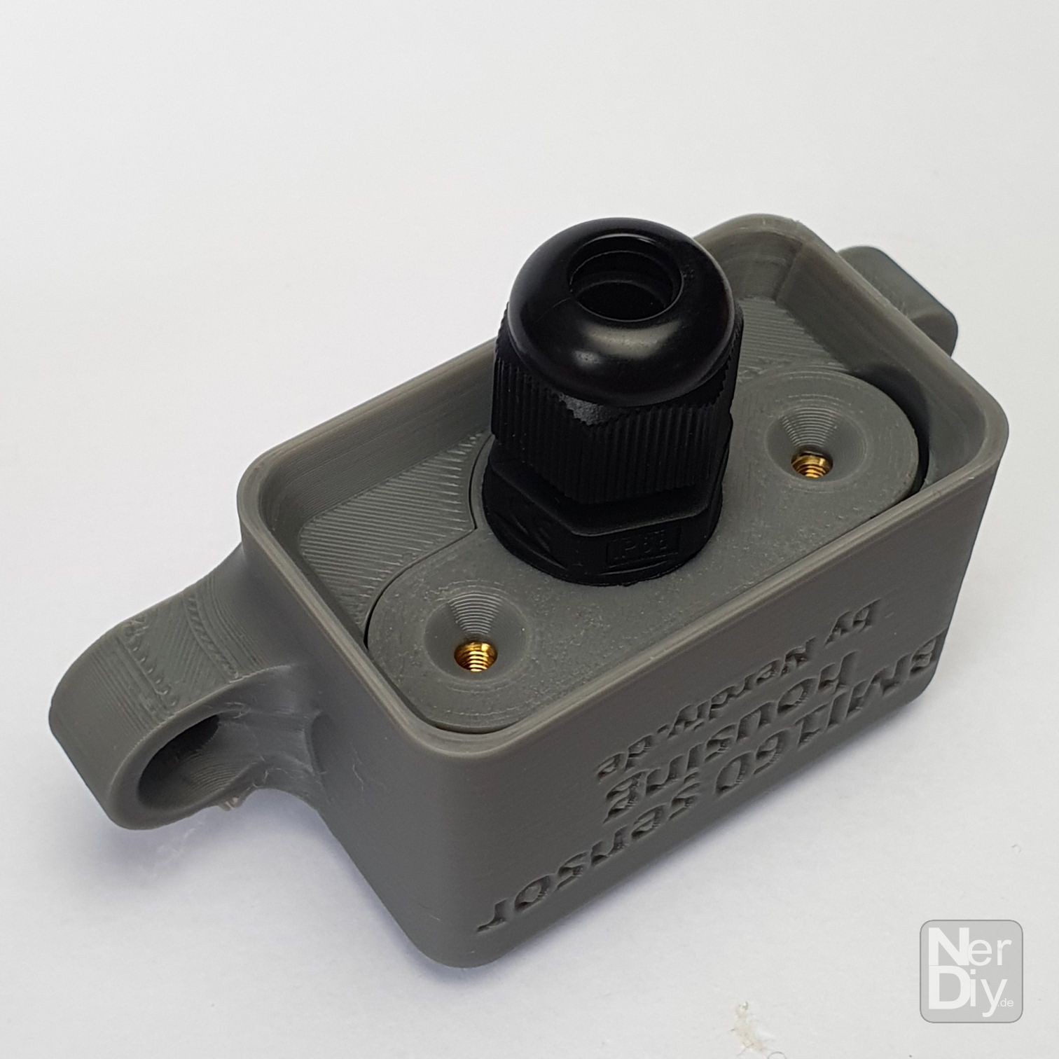
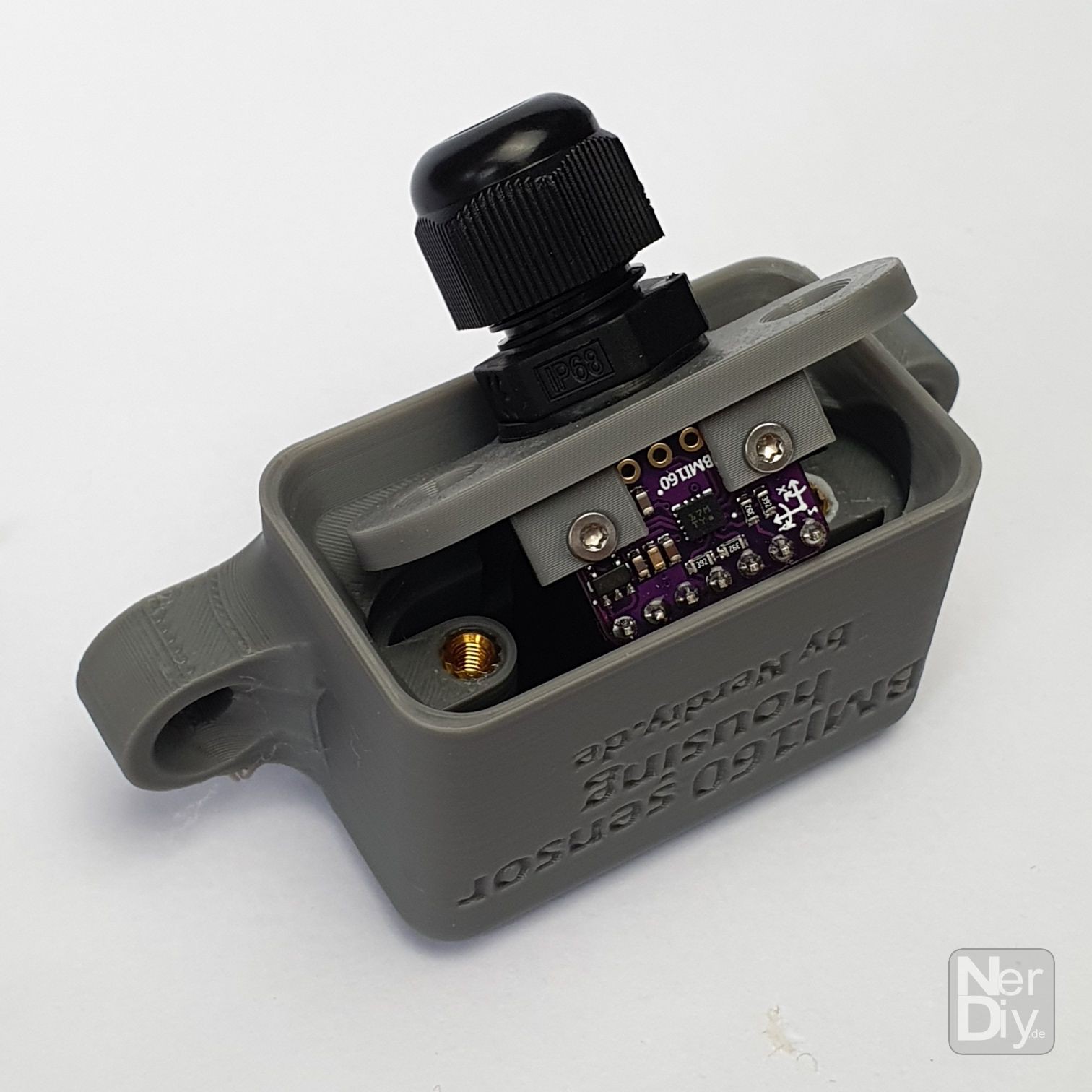
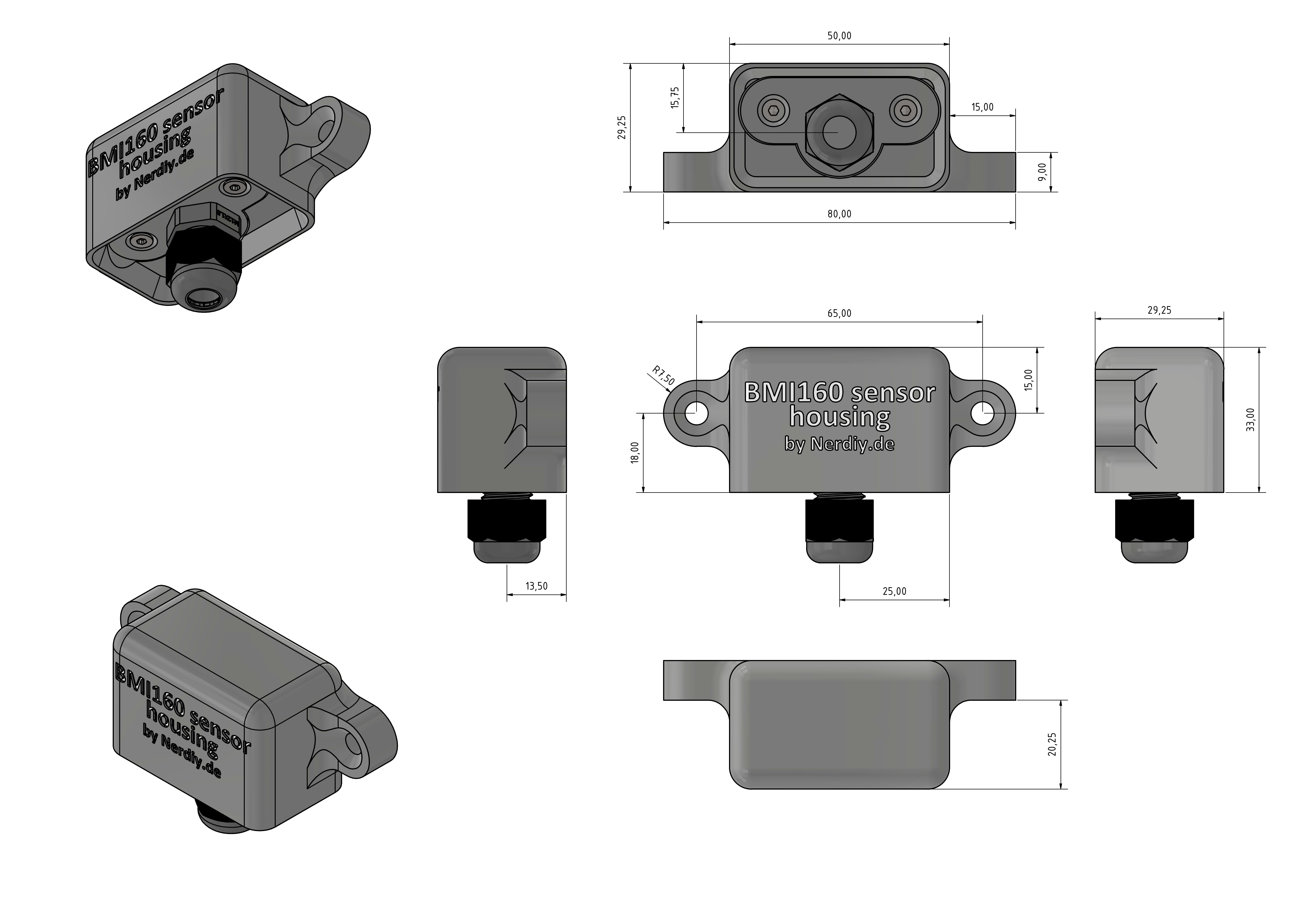
Mountable BMI160 Housing to measure the elevation angle
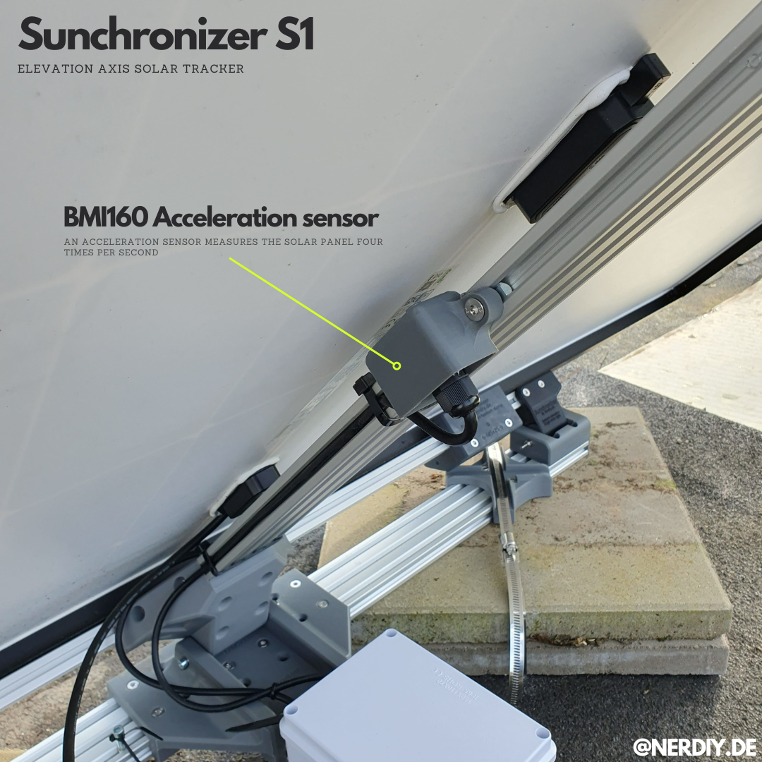
04/22/2024 at 18:51 • 0 commentsOne important sensor for the function of the Sunchronizer is the BMI160 acceleration sensor.
To ensure that the SolarPanel is always perfectly aligned with the sun, the elevation angle of the panel is regularly measured and adjusted accordingly thanks to the BMI160.
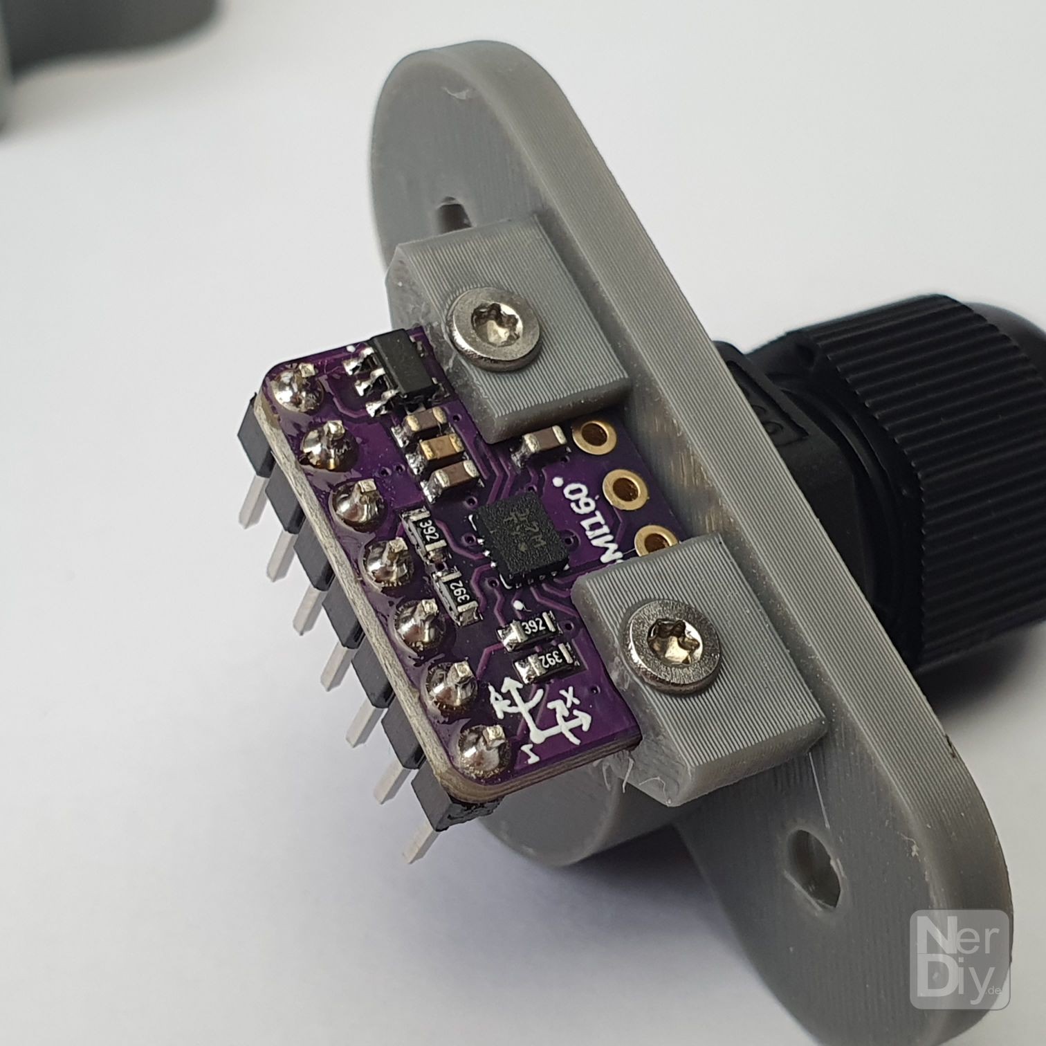
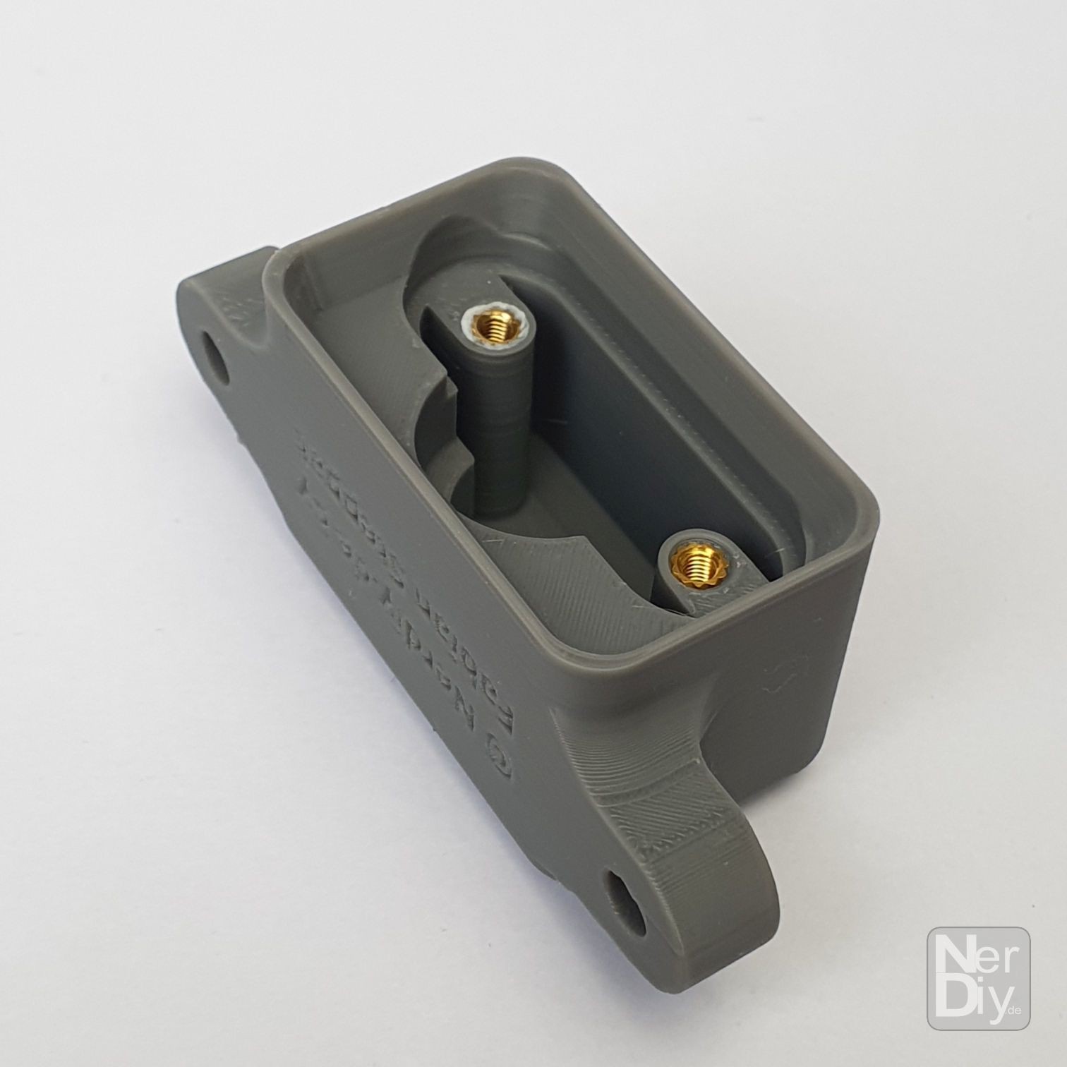
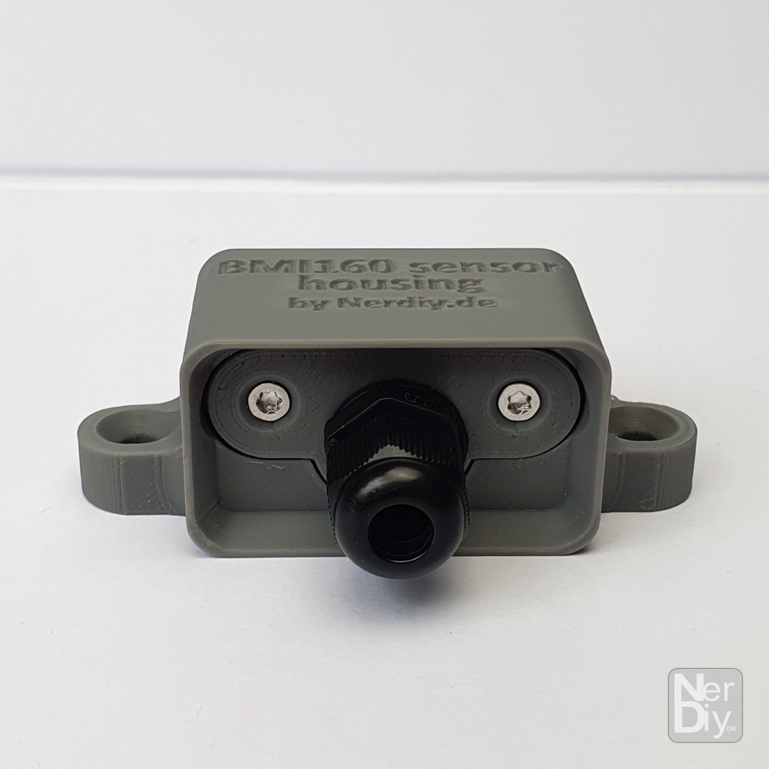
Thanks to the housing shown, the BMI160 can be mounted splash-proof on the support profile, which later also holds the solar panel.
The STLs for the housing can be found on my blog at: https://nerdiy.de/en/product-2/bmi160-modul-gehaeuse-3d-druckbar-stl-dateien/
![]()
![]()
![]()
![]()
![]()
![]()
![]()
![]()
-
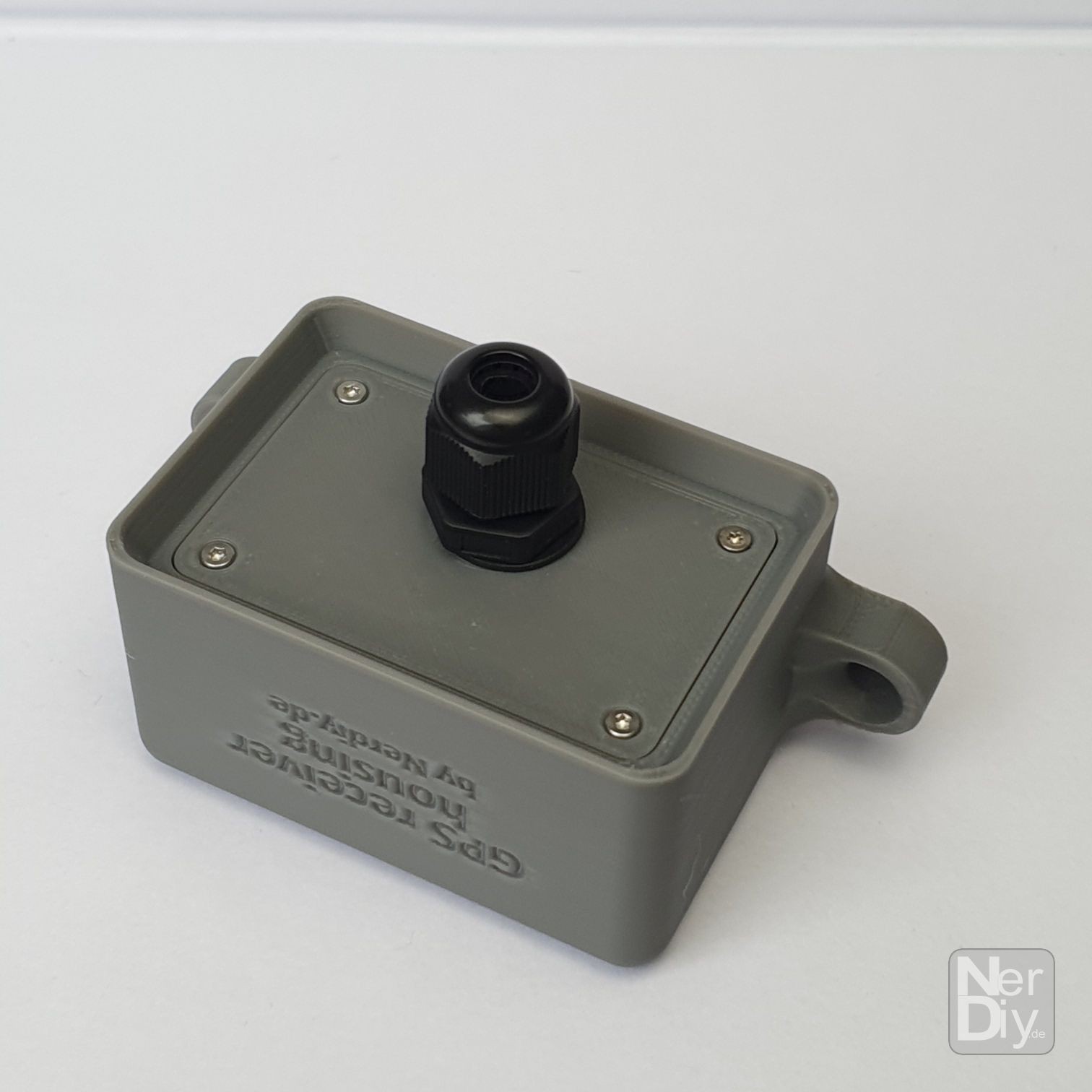
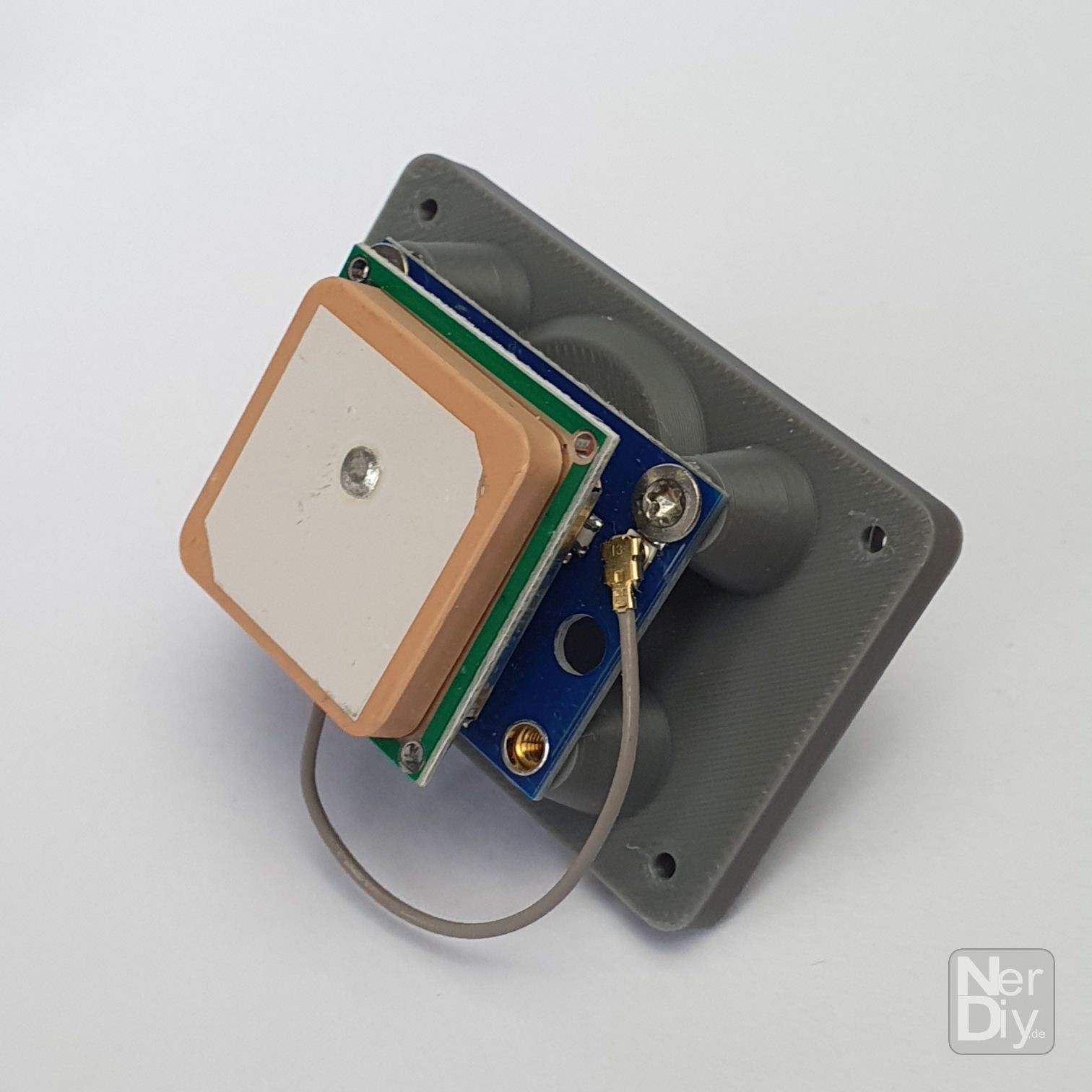
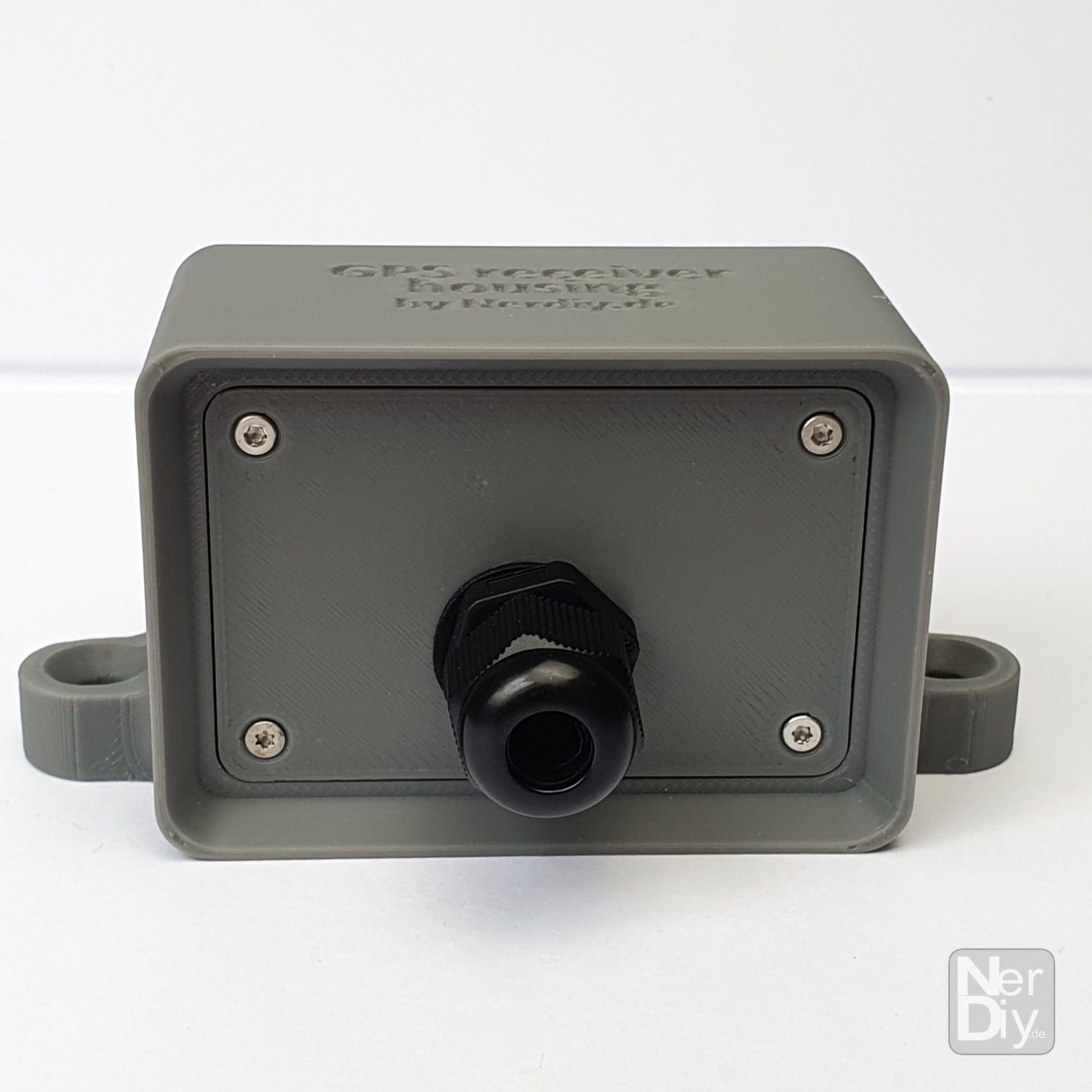
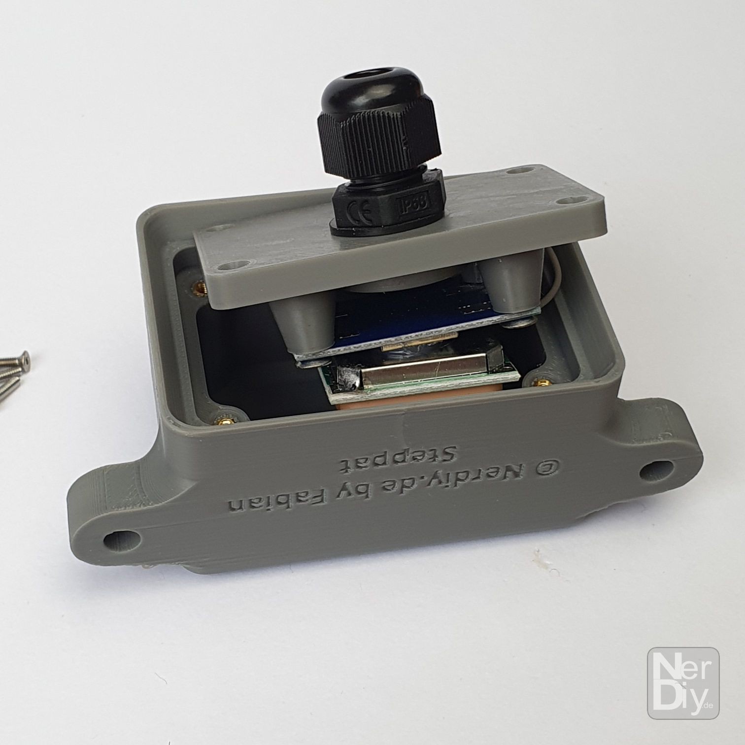
Splash proof NEO7MV2 GPS receiver housing
04/22/2024 at 18:51 • 0 commentsIn order for the control electronics of the Sunchronizer to calculate the correct sun angle, it needs to know the exact time as well as the current position.
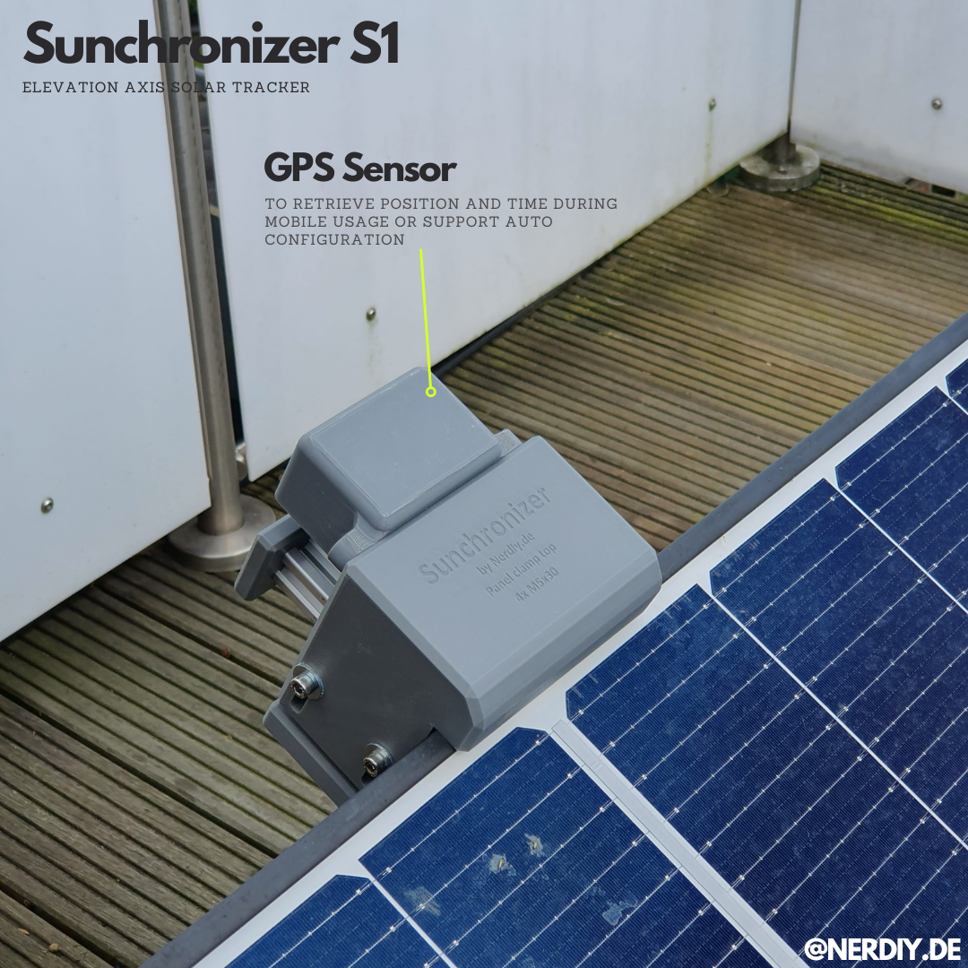
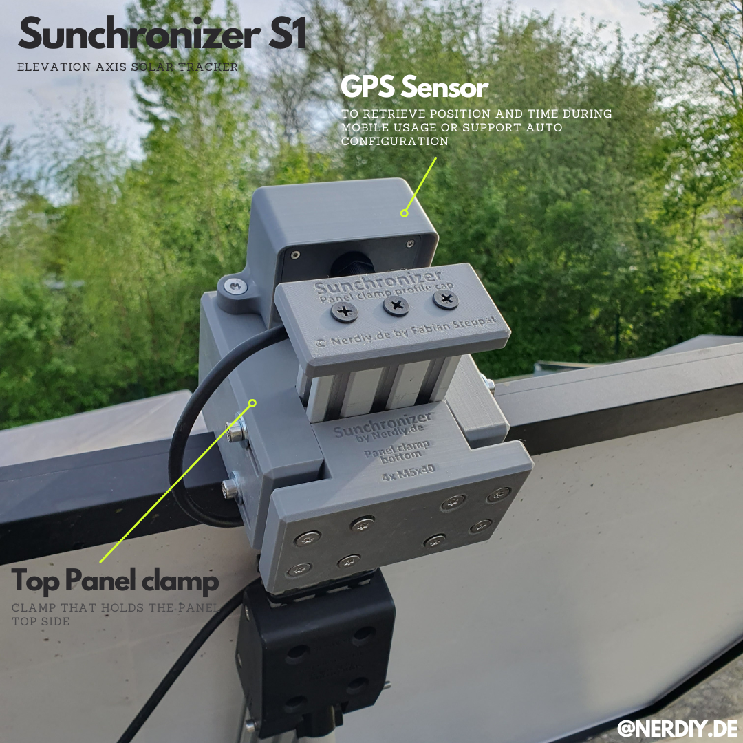
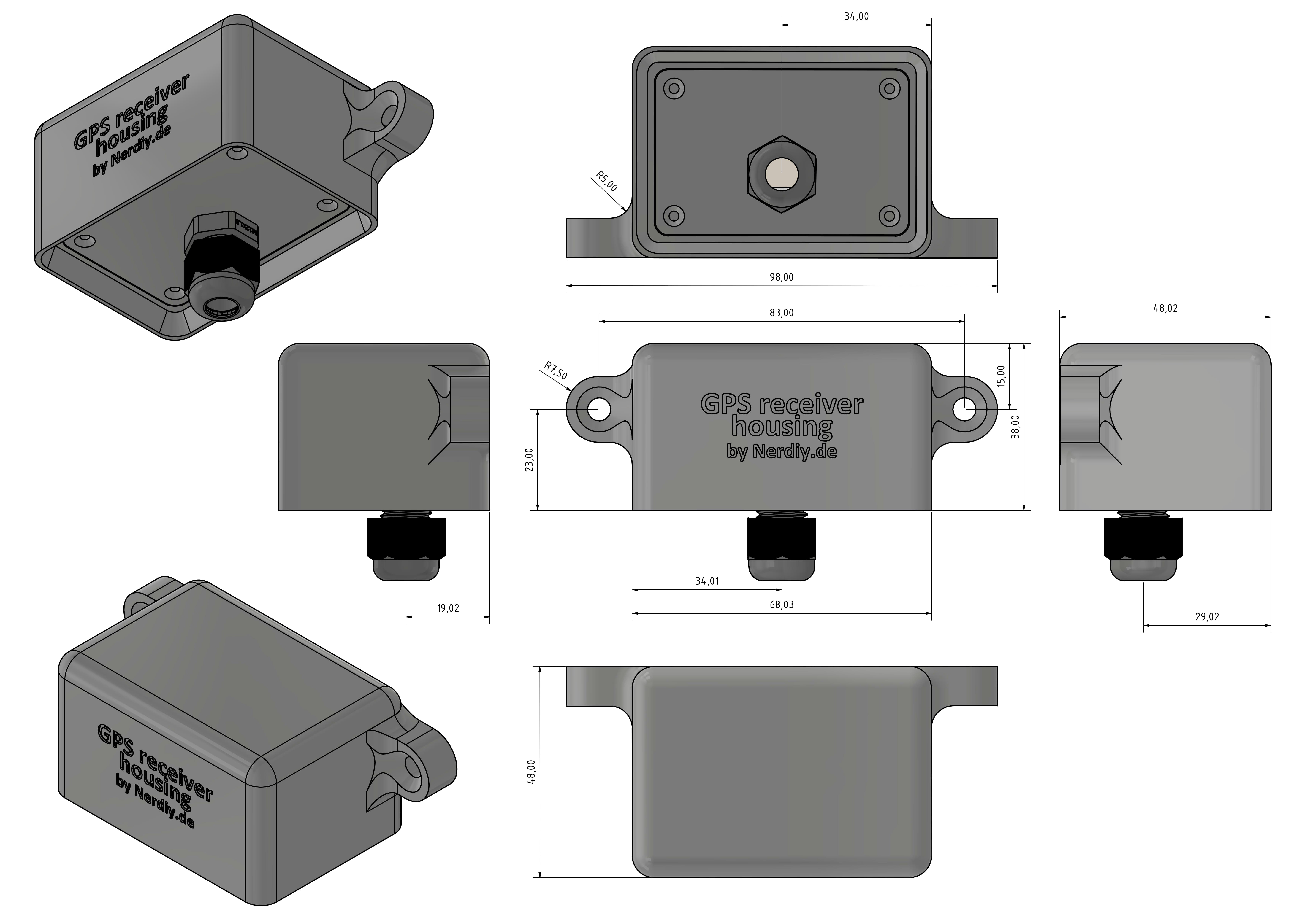
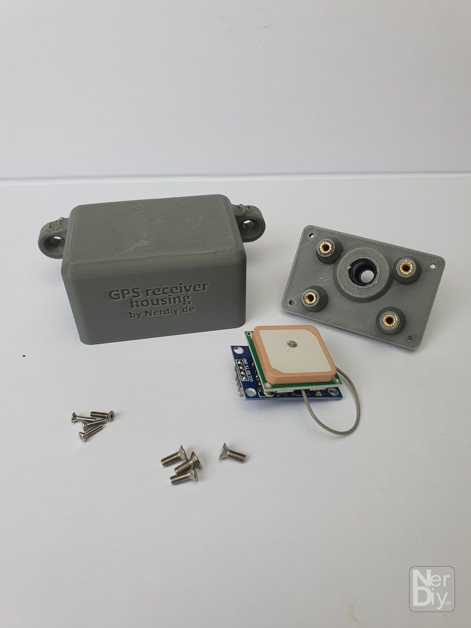
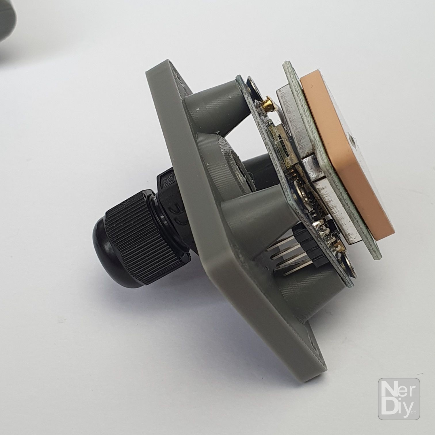
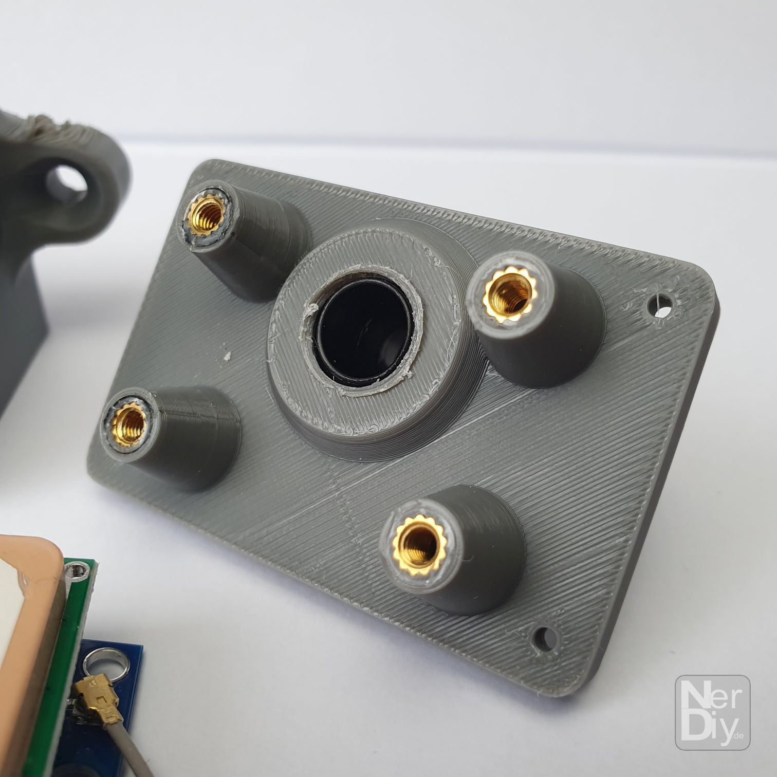
For this purpose, I installed a GPS receiver on the Sunchronizer. I designed the housing shown so that the GPS antenna has a clear view of the sky and is protected from splash water/rain at the same time.
The GPS module can be installed in it and then attached to the aluminum profiles of the Sunchronizer with the housing and two M5 screws.
The STLs of the housing can be found on my blog at: https://nerdiy.de/produkt/neo7mv2-gps-empfaenger-modul-gehaeuse-3d-druckbar-stl-dateien/
![]()
![]()
![]()
![]()
![]()
![]()
![]()
![]()
![]()
![]()
Sunchronizer - Single/Dual Axis Solar Tracker
3D printable ESPHome based 400W Single or Dual Axis Solar Tracker