-
1Overview
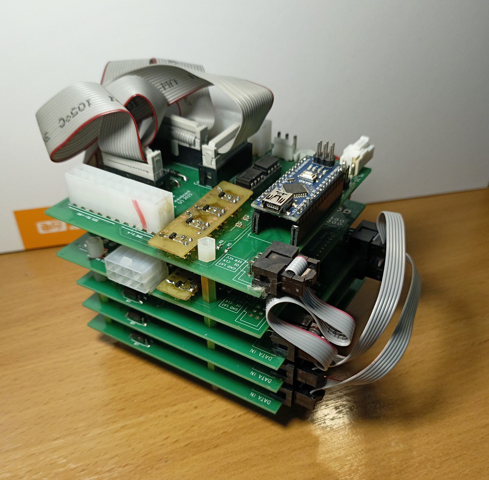
The control unit is assembled from five boards - three blinker key boards at the bottom and two control boards at the top, installed one above the other like a sandwich:
![]()
-
2Blinker keys boards
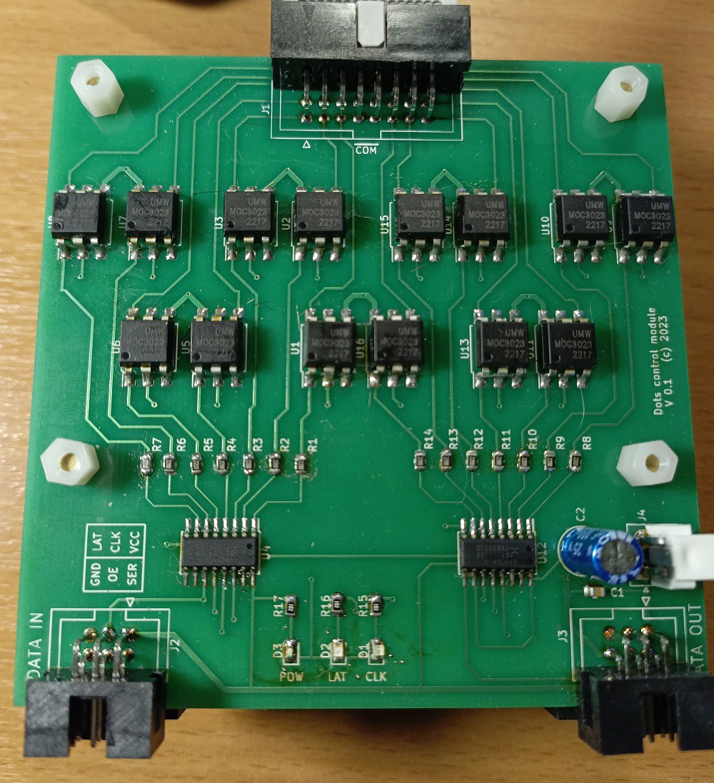
The purpose of the board is to switch of individual blinkers. Each board contains 14 optotriacs controlled by two shift registers. The shift registers of the three boards are chained, allowing up to 42 outputs to be controlled. Since the number of flip-dots on each digit block is only 35; seven outputs on the bottom board are not used.
![]()
-
3Main board
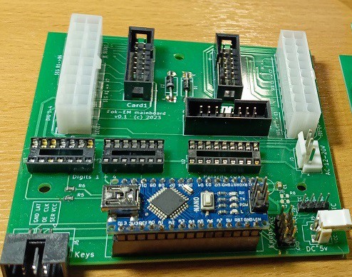
The main board is a heard of the control module. It contains a Arduino Nano board and two polarity switches. Most of the panel is occupied by connectors linked it to key boards and blinker blocks
![]()
-
4Button board
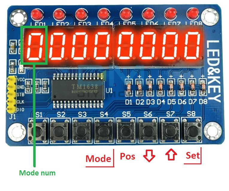
To set the time and date, a button module based on TM1638 was used
Flip-dot clock control board
Controlling flip-dot clock modules by AC - now you don't need complex polarity reversal circuits
 board707


Discussions
Become a Hackaday.io Member
Create an account to leave a comment. Already have an account? Log In.