I searched for a silicone mould kit and the first result had a nice colour so I used it in the model:

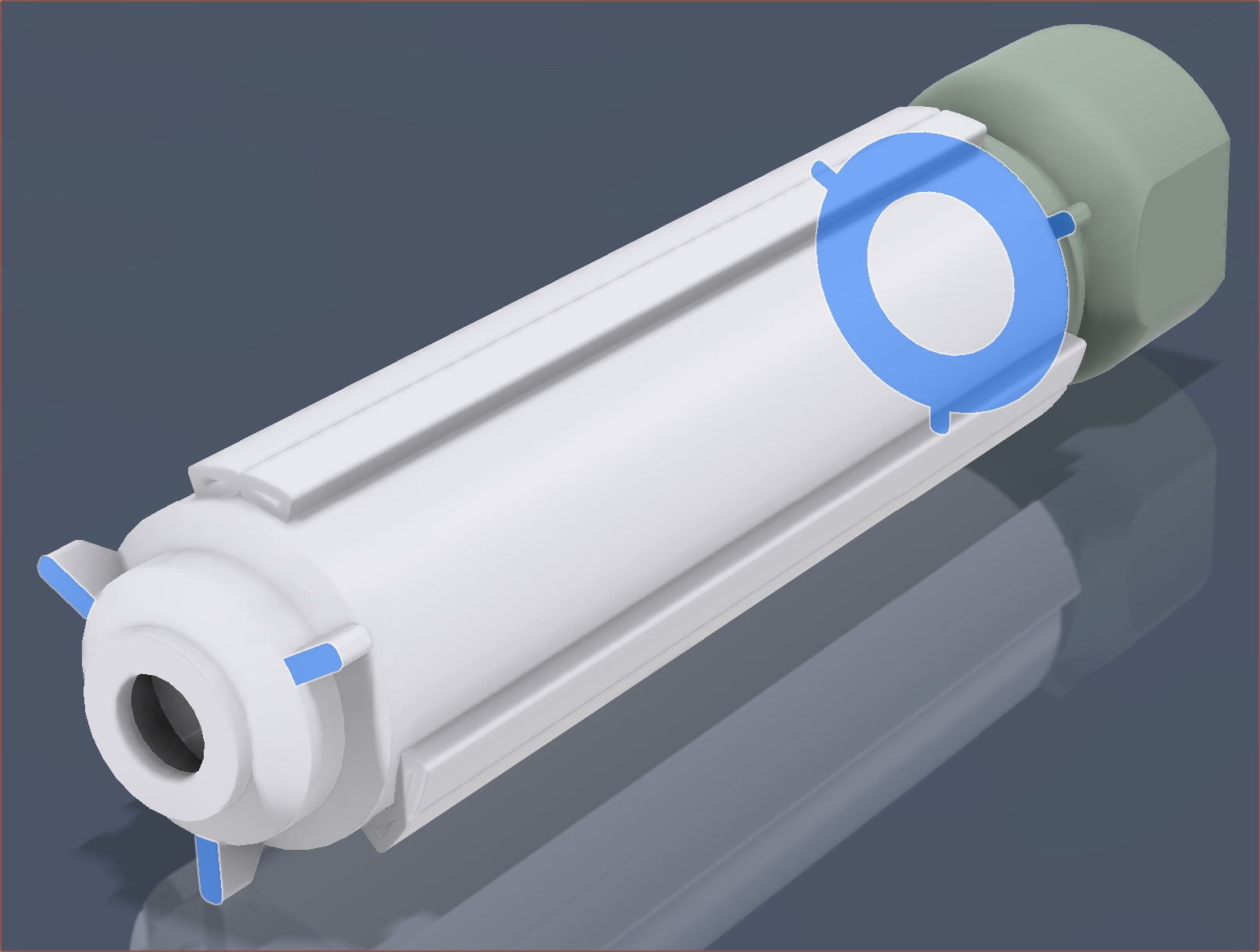
The bell and overmould have 3 spokes that help align to the toroid and front cap respectively:
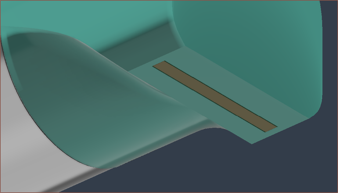
I also confirmed that FR-4 does not absorb water, so I should be fine in the bottom of the PCB being exposed:
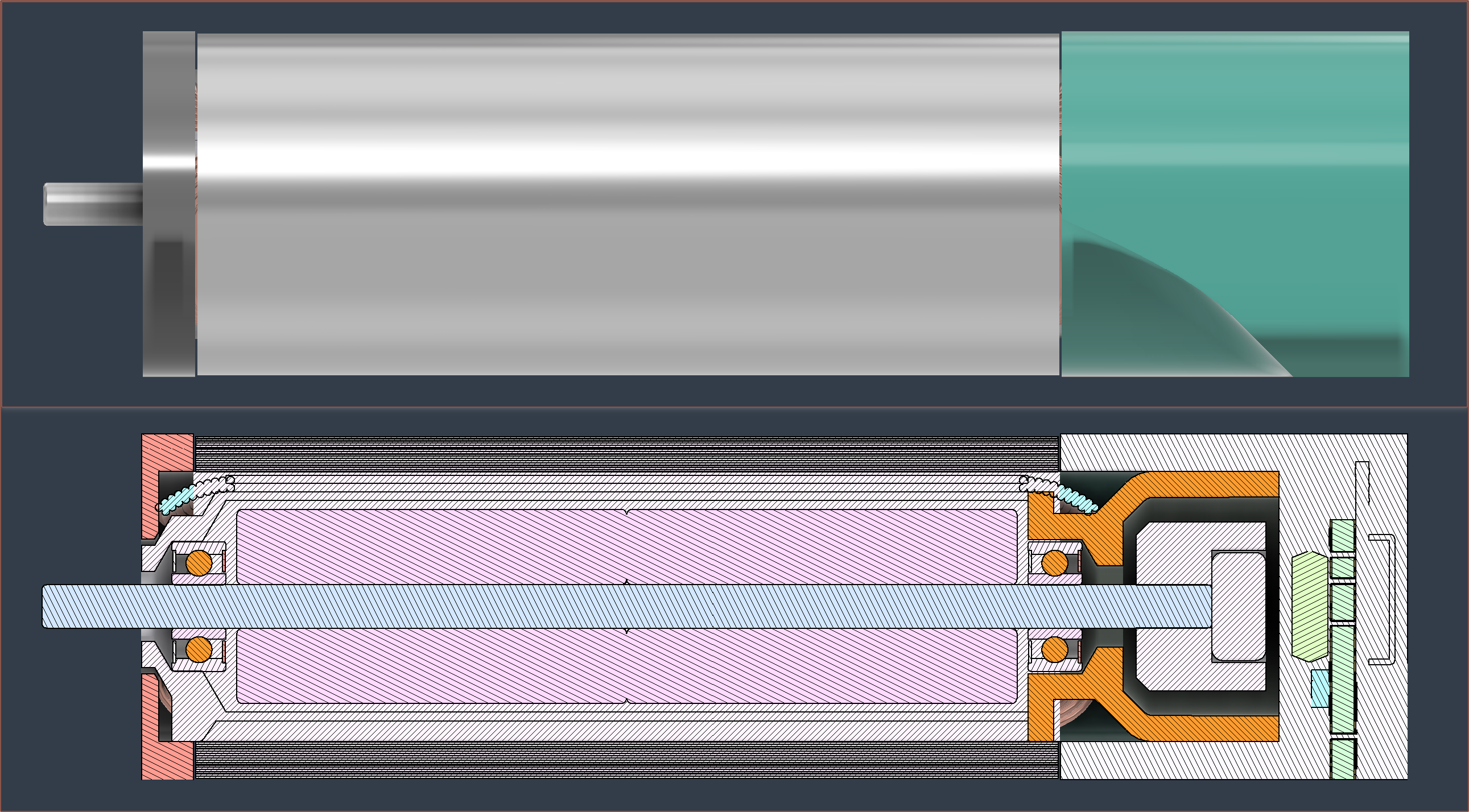
I like that the final result looks like it's just a standard servo inside a manufacturer's product catalog:
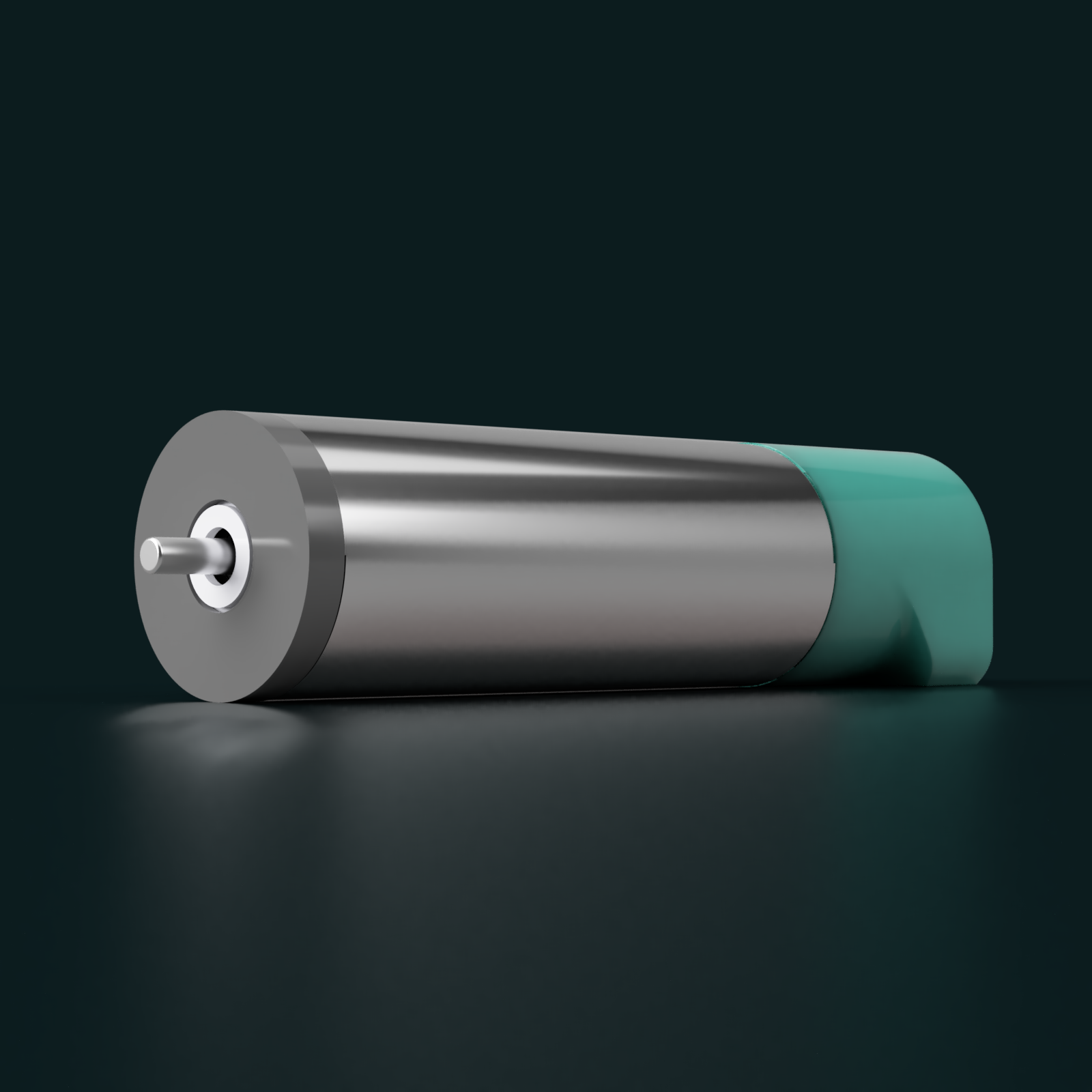
Next steps would be to create the buildables for the servo.
- .3MF files that can be used with vase mode
- Silicone mould jig, perhaps adding draft angles
- JLC assembly files
- etc
In other news, I received a progress update from ABM Magnetics:
We have completed the production of rotor samples.
However, the tolerance of the shaft was increased during production, resulting in the outer diameter of the product reaching about 9.20mm after the magnet was assembled, which exceeded the tolerance of the drawing.
Our plan is to re-produce the shaft for production, which will be around August 25th.
Essentially, the range of diameters was between 9.00 and 9.20mm but the tolerance specified in my drawing was 9.00 - 9.05mm. The reason for the tight tolerances is because
- changes in diameter affect the torque constant, and
- the rotor needs to be able to spin freely in the overmould.
 kelvinA
Discussions
Become a Hackaday.io Member
Create an account to leave a comment. Already have an account? Log In.