 kelvinA
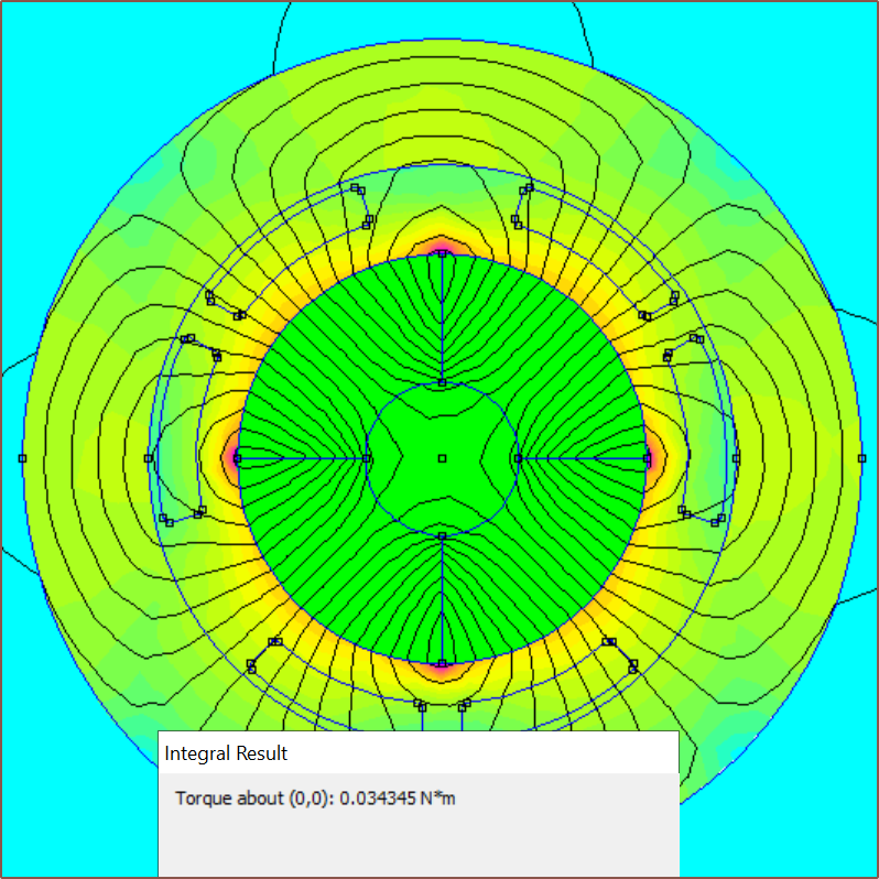
During my research, I stumbled on this tutorial article that describes how to set up a BLDC motor simulation. Almost immediately, I was downloading and installing FEMM and exporting the simulation sketch from Fusion.
The first thing I learned was that, as far as the simulation is concerned, if the item isn't conductive and/or magnetic, it might as well be air. Thus, the overmould isn't part of these simulations because it wouldn't change the result.
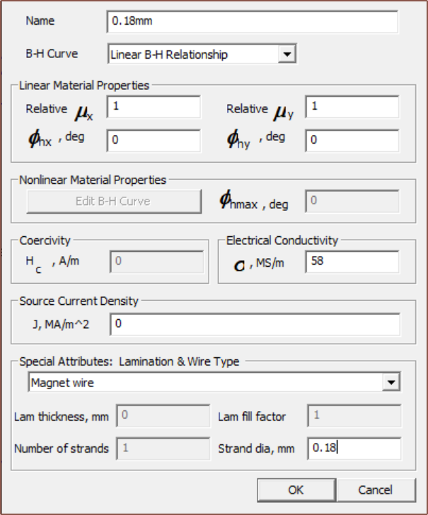
I started with at 0.2mm copper wire option, but I later found out that I can customise the material so I (eventually) renamed it to simply "Coil" and changed the wire diameter to whatever I wanted to simulate. Usually this value was 0.18mm but I did run some simulations with 0.25mm wire.
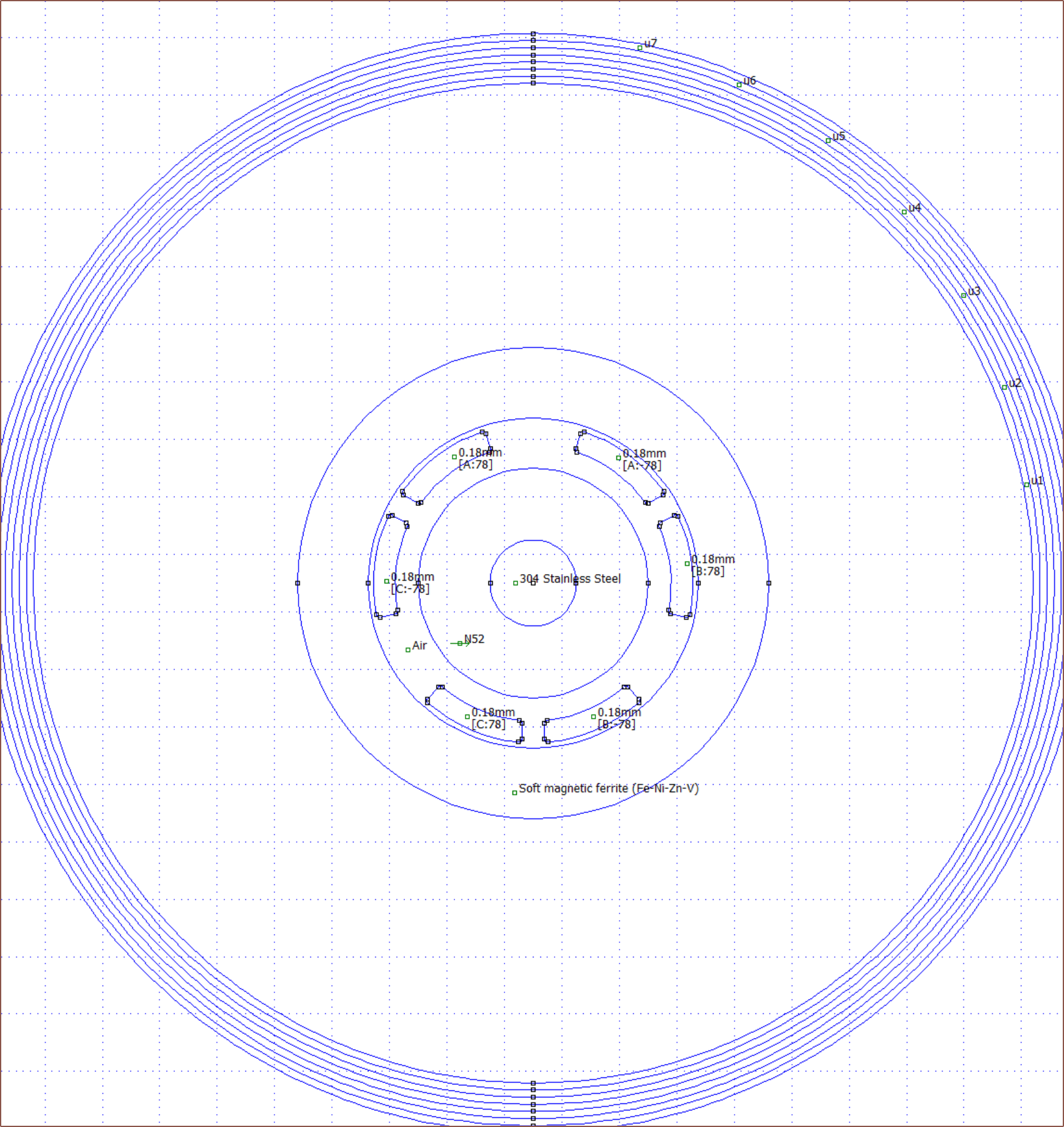
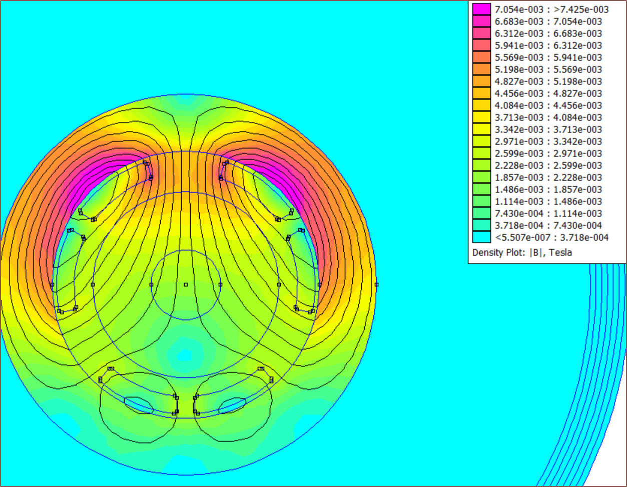
So I soon had my first simulation actually set up. I've been spending months on-and-off researching for a simulation solution for #Tetrinsic [gd0041] and I now had something at a time when I should actually be in bed. This is the first simulation result of the magnetic field:
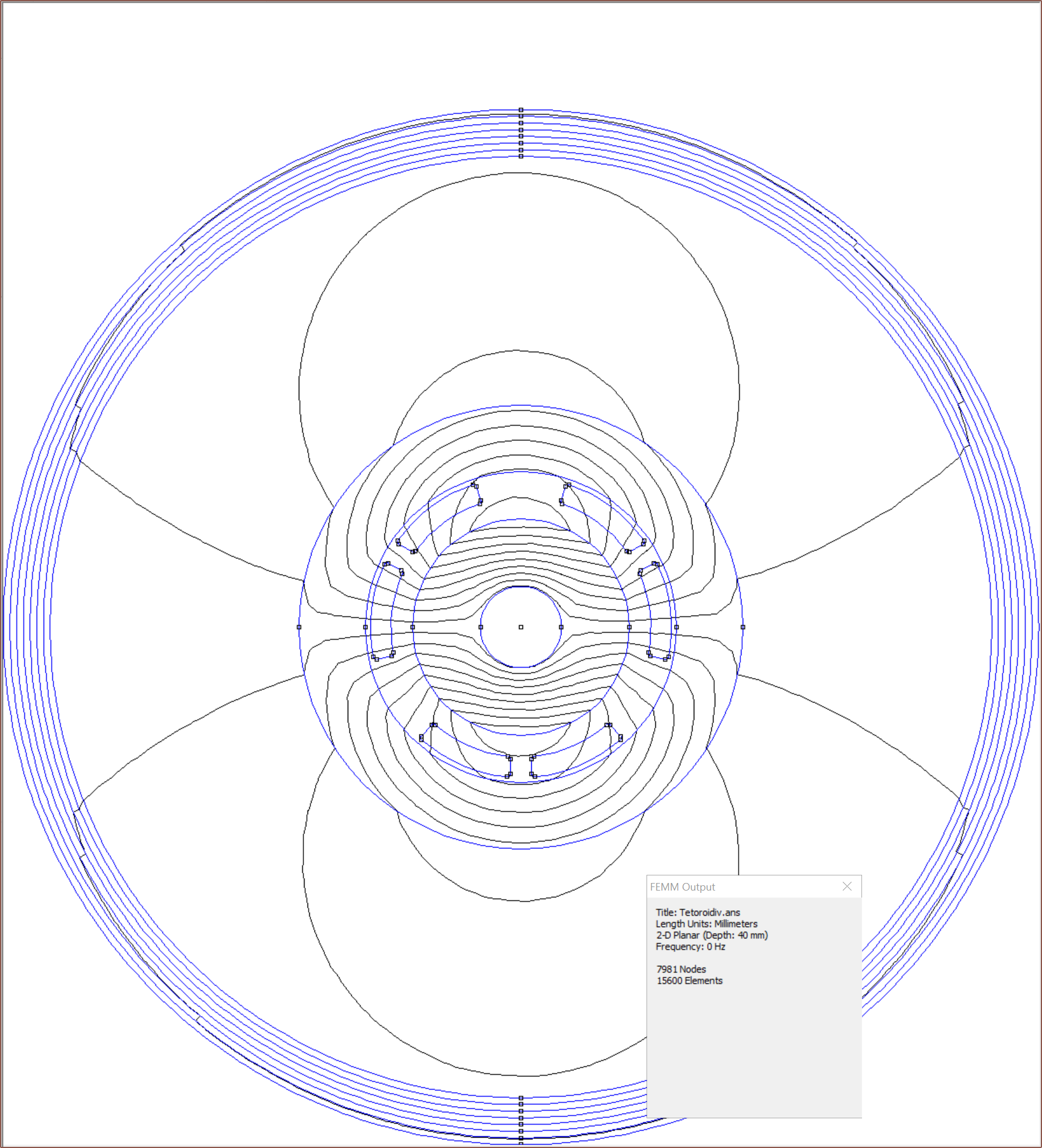
I found out how to turn on the nice colours. I also turned off the magnet to confirm that the coils are actually configured correctly:
Fast forward, I tried quite a few configurations with 1A though the coils so that I could get the torque constant directly.
- 2 pole pairs increased torque essentially by a factor of 2. Additionally, the flux is better contained inside the toroid than 1 pole pair.
- 3 pole pairs had almost no torque. Allegedly, such a configuration is "unbalanced".
- 6 coils (20T) were much weaker than 3.
- Diverging from 8mm rotor reduced performance.
- 0.18mm wire seemed like the best balance of turn count and resistance.
Effectively, 1 pole pair is not ideal. It means I need twice the current and thus 4x the power to get the same torque out as a 2-pole pair motor. I'm currently asking around on Alibaba to see what my options are.
Discussions
Become a Hackaday.io Member
Create an account to leave a comment. Already have an account? Log In.