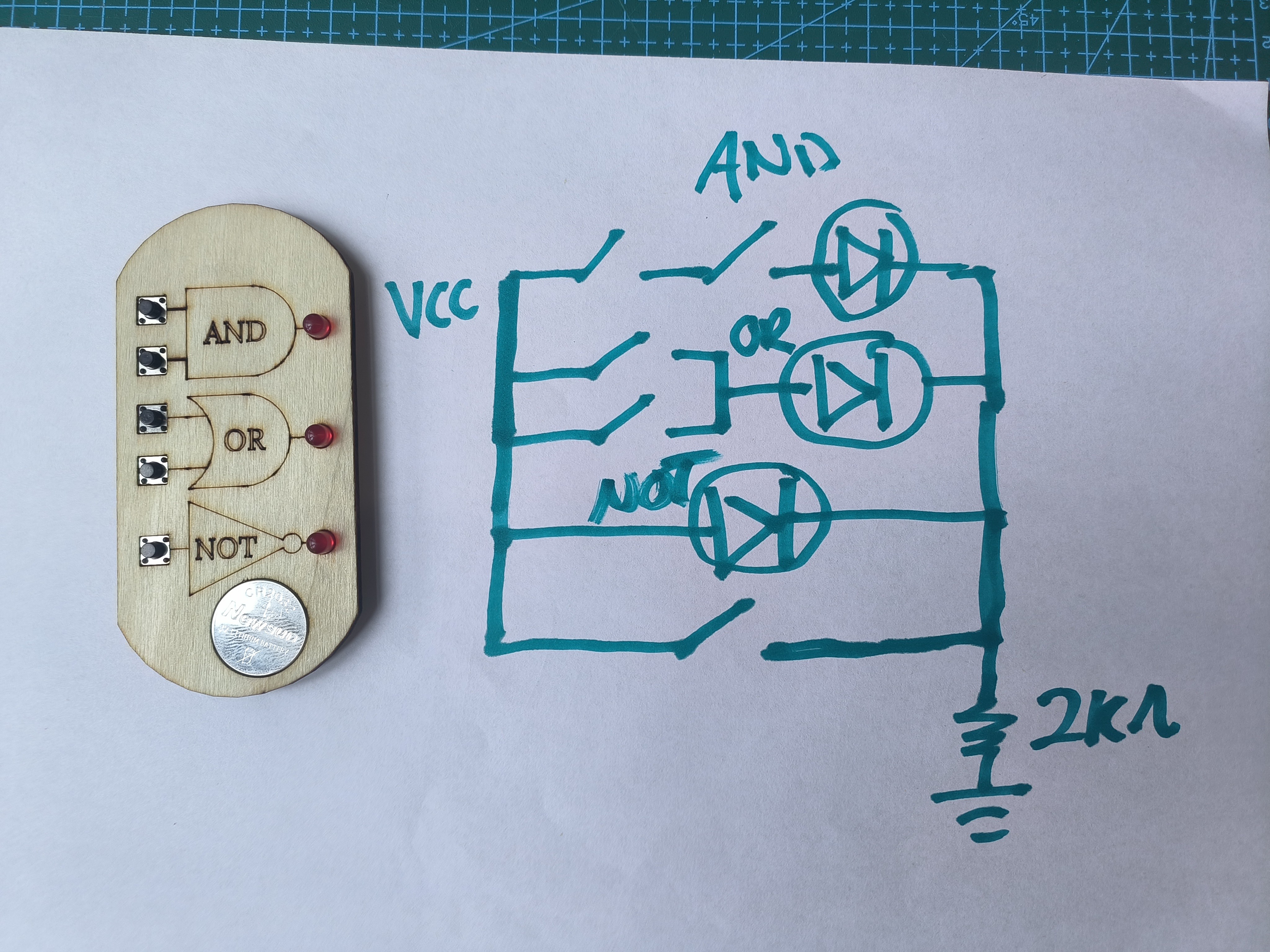
Circuit Diagram
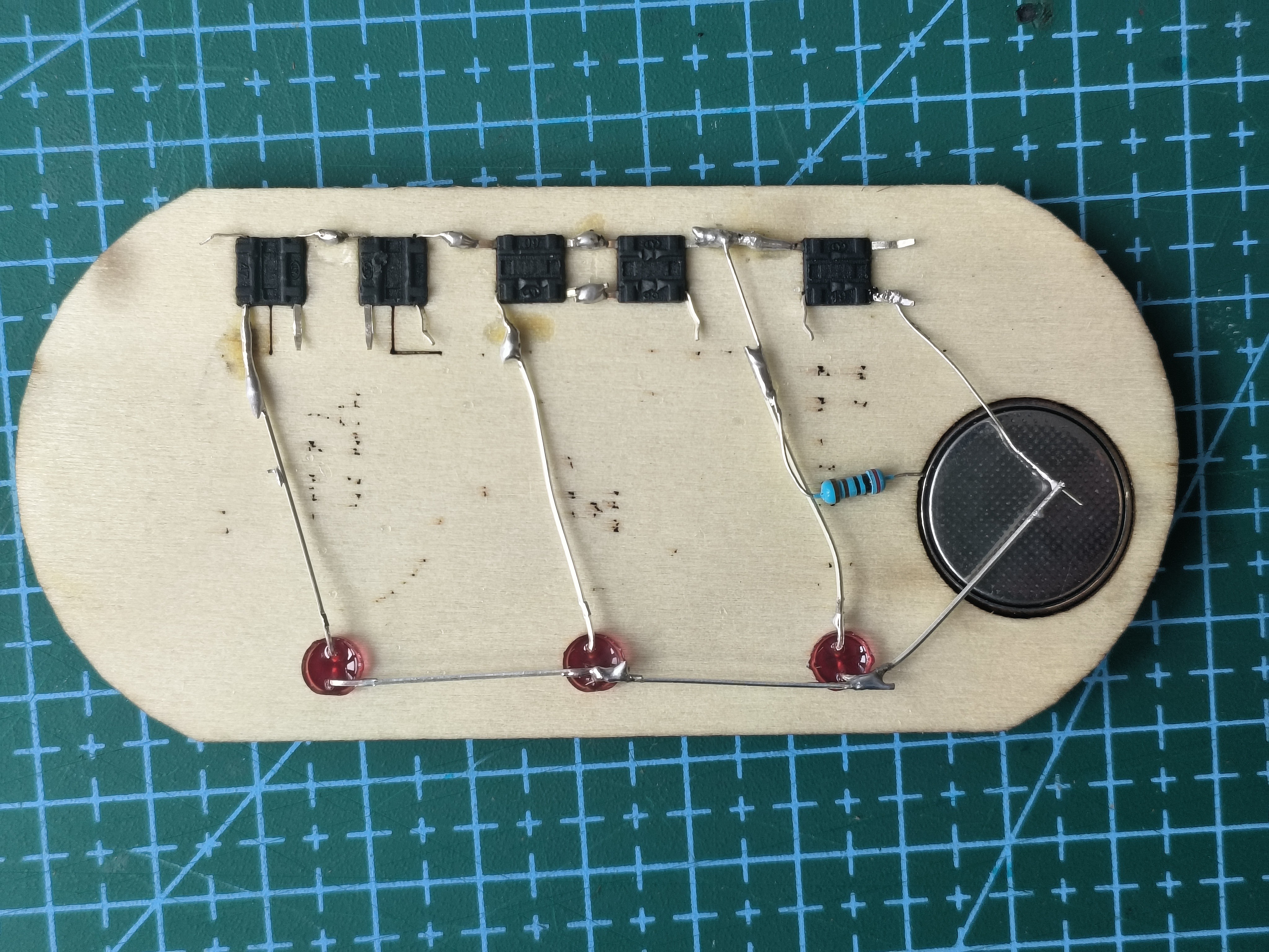
The Soldering
Powered by 3V CR2032 coin battery.
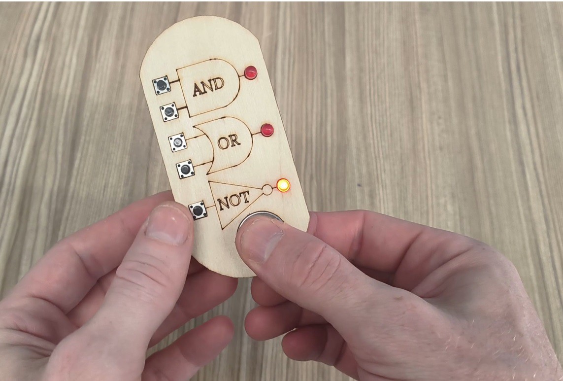
Final Product
This project requires minimal components:
3 LEDs
5 Buttons
1 Resistor
PCB or access to a 3D printer/laser cutter.
Join me as we delve into the fascinating world of logic gates in a hands-on and enjoyable manner!
Link to the Schematic and laser cutter files and be downloaded here.
https://drive.google.com/drive/folder...
This is a very simple project, but I still sorta like it.
There is one thing though I do not fully understand.
From the schematic (and the photograph of the backside of the PCB) it looks there is no on/off switch and the battery will be quickly drained by the led on the NOT gate.
Maybe you intend to use the two wires over the battery as a switch, so the thing only turns on when the battery is pinched as in the last photograph, but neither the battery nor this implied switch is in the schematic and you may want to add those to the schematic or at least mention it in the description.