Using a solder paste dispensing needle, we first add solder paste to each component pad, one by one. We're using standard 37/63 solder paste here.
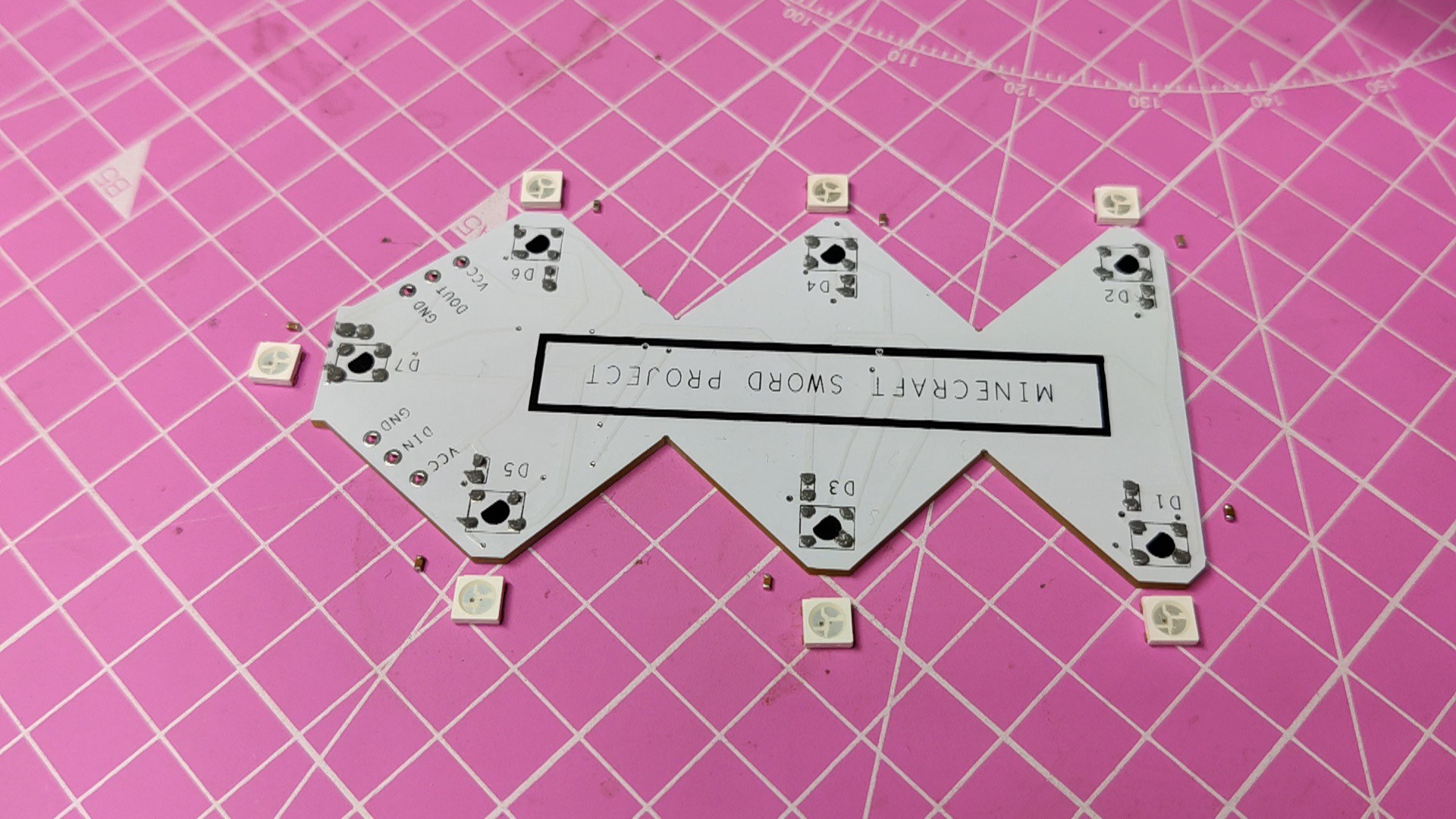
Next, we pick and place all the SMD components in their places on the PCB using an ESD tweezer.
With extreme caution, we lifted the complete circuit board and placed it on the SMT hotplate, which increases the PCB's temperature to the point at which the solder paste melts and all of the components are connected to their pads.
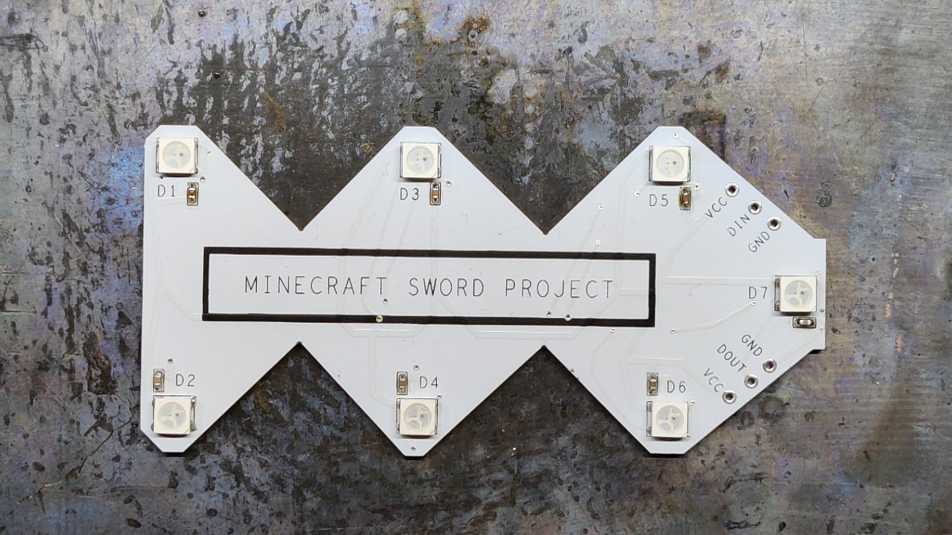
We are preparing a total of five LED boards to be used in the Sword Assembly.
2
CIRCUIT ASSEMBLY
After preparing the LED board, we prepare the main circuit board, which starts by adding solder paste to each component pad one by one.
Next, we all place the SMD components in their positions using a tweezer.
We then pick the whole circuit and place it on the SMT Reflow hotplate for the reflow process, which heats the PCB up to the solder paste melting temperature, reflowing all the SMD components with the PCB.
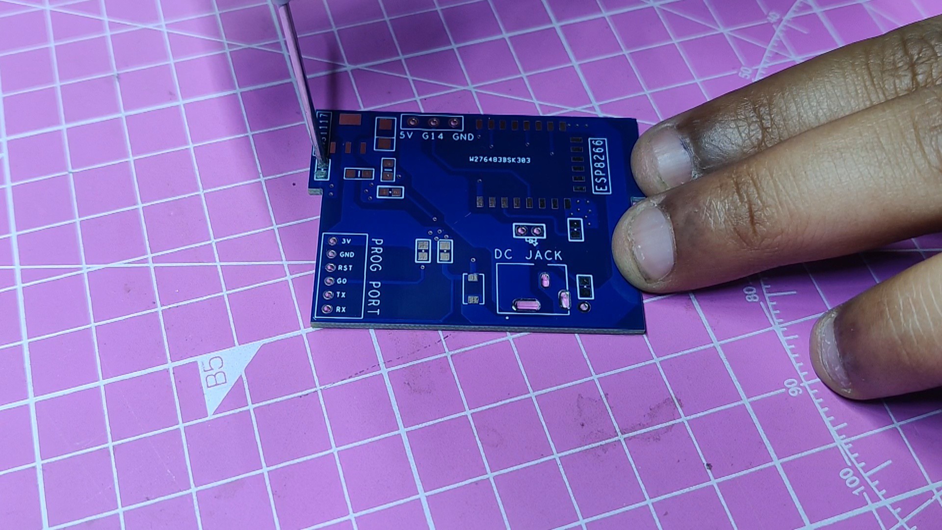
Next, we add the remaining THT components on the PCB which were the DC Barrel jack and the indicator LED.
We then soldered their pads using a soldering iron and the Circuit PCB is now complete.
3
Flashing the ESP12
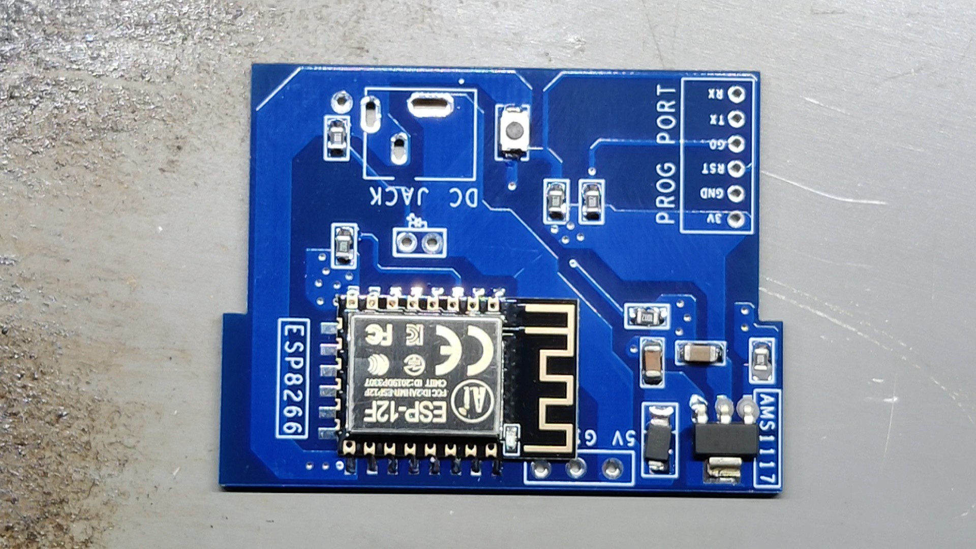
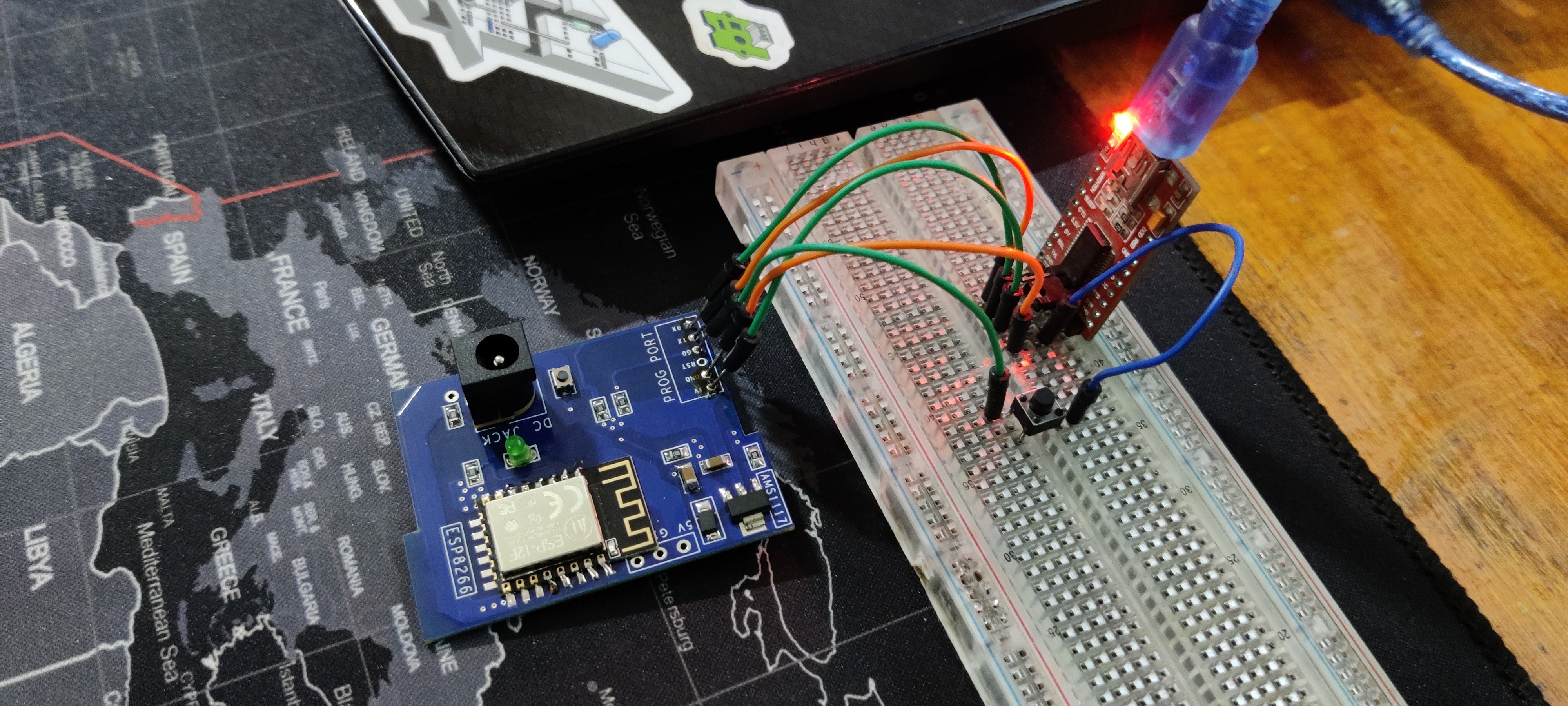
Next is the Flashing process of the main circuit's ESP12F Module.
The usual FTDI board method, which requires connecting a flashing button between GPIO 0 and GND Port, is being used to program the ESP12F Module. During uploading, the ESP12F enters programming mode by long pressing the Flash button first, followed by the reset button.
Here's an article about programming ESP12F with FTDI Board for more details:
Here's the code which was used in this project and its a simple one.
#define FASTLED_ALLOW_INTERRUPTS 0#include<FastLED.h>
FASTLED_USING_NAMESPACE
#define DATA_PIN 14#define NUM_LEDS 28#define MAX_POWER_MILLIAMPS 600#define LED_TYPE WS2812B#define COLOR_ORDER GRB//////////////////////////////////////////////////////////////////////////
CRGB leds[NUM_LEDS];
voidsetup(){
delay( 3000); // 3 second delay for boot recovery, and a moment of silence
FastLED.addLeds<LED_TYPE,DATA_PIN,COLOR_ORDER>(leds, NUM_LEDS)
.setCorrection( TypicalLEDStrip );
FastLED.setMaxPowerInVoltsAndMilliamps( 5, MAX_POWER_MILLIAMPS);
}
voidloop(){
EVERY_N_MILLISECONDS( 20) {
pacifica_loop();
FastLED.show();
}
}
CRGBPalette16 pacifica_palette_1 =
{ 0x000507, 0x000409, 0x00030B, 0x00030D, 0x000210, 0x000212, 0x000114, 0x000117,
0x000019, 0x00001C, 0x000026, 0x000031, 0x00003B, 0x000046, 0x14554B, 0x28AA50 };
CRGBPalette16 pacifica_palette_2 =
{ 0x000507, 0x000409, 0x00030B, 0x00030D, 0x000210, 0x000212, 0x000114, 0x000117,
0x000019, 0x00001C, 0x000026, 0x000031, 0x00003B, 0x000046, 0x0C5F52, 0x19BE5F };
CRGBPalette16 pacifica_palette_3 =
{ 0x000208, 0x00030E, 0x000514, 0x00061A, 0x000820, 0x000927, 0x000B2D, 0x000C33,
0x000E39, 0x001040, 0x001450, 0x001860, 0x001C70, 0x002080, 0x1040BF, 0x2060FF };
voidpacifica_loop(){
// Increment the four "color index start" counters, one for each wave layer.// Each is incremented at a different speed, and the speeds vary over time.staticuint16_t sCIStart1, sCIStart2, sCIStart3, sCIStart4;
staticuint32_t sLastms = 0;
uint32_t ms = GET_MILLIS();
uint32_t deltams = ms - sLastms;
sLastms = ms;
uint16_t speedfactor1 = beatsin16(3, 179, 269);
uint16_t speedfactor2 = beatsin16(4, 179, 269);
uint32_t deltams1 = (deltams * speedfactor1) / 256;
uint32_t deltams2 = (deltams * speedfactor2) / 256;
uint32_t deltams21 = (deltams1 + deltams2) / 2;
sCIStart1 += (deltams1 * beatsin88(1011,10,13));
sCIStart2 -= (deltams21 * beatsin88(777,8,11));
sCIStart3 -= (deltams1 * beatsin88(501,5,7));
sCIStart4 -= (deltams2 * beatsin88(257,4,6));
// Clear out the LED array to a dim background blue-green
fill_solid( leds, NUM_LEDS, CRGB( 2, 6, 10));
// Render each of four layers, with different scales and speeds, that vary over time
pacifica_one_layer( pacifica_palette_1, sCIStart1, beatsin16( 3, 11 * 256, 14 * 256), beatsin8( 10, 70, 130), 0-beat16( 301) );
pacifica_one_layer( pacifica_palette_2, sCIStart2, beatsin16( 4, 6 * 256, 9 * 256), beatsin8( 17, 40, 80), beat16( 401) );
pacifica_one_layer( pacifica_palette_3, sCIStart3, 6 * 256, beatsin8( 9, 10,38), 0-beat16(503));
pacifica_one_layer( pacifica_palette_3, sCIStart4, 5 * 256, beatsin8( 8, 10,28), beat16(601));
// Add brighter 'whitecaps' where the waves lines up more
pacifica_add_whitecaps();
// Deepen the blues and greens a bit
pacifica_deepen_colors();
}
// Add one layer of waves into the led arrayvoidpacifica_one_layer( CRGBPalette16& p, uint16_t cistart, uint16_t wavescale, uint8_t bri, uint16_t ioff){
uint16_t ci = cistart;
uint16_t waveangle = ioff;
uint16_t wavescale_half = (wavescale / 2) + 20;
for( uint16_t i = 0; i < NUM_LEDS; i++) {
waveangle += 250;
uint16_t s16 = sin16( waveangle ) + 32768;
uint16_t cs = scale16( s16 , wavescale_half ) + wavescale_half;
ci += cs;
uint16_t sindex16 = sin16( ci) + 32768;
uint8_t sindex8 = scale16( sindex16, 240);
CRGB c = ColorFromPalette( p, sindex8, bri, LINEARBLEND);
leds[i] += c;
}
}
// Add extra 'white' to areas where the four layers of light have lined up brightlyvoidpacifica_add_whitecaps(){
uint8_t basethreshold = beatsin8( 9, 55, 65);
uint8_t wave = beat8( 7 );
for( uint16_t i = 0; i < NUM_LEDS; i++) {
uint8_t threshold = scale8( sin8( wave), 20) + basethreshold;
wave += 7;
uint8_t l = leds[i].getAverageLight();
if( l > threshold) {
uint8_t overage = l - threshold;
uint8_t overage2 = qadd8( overage, overage);
leds[i] += CRGB( overage, overage2, qadd8( overage2, overage2));
}
}
}
// Deepen the blues and greensvoidpacifica_deepen_colors(){
for( uint16_t i = 0; i < NUM_LEDS; i++) {
leds[i].blue = scale8( leds[i].blue, 145);
leds[i].green= scale8( leds[i].green, 200);
leds[i] |= CRGB( 2, 5, 7);
}
}
This code is for creating a mesmerizing animation called "Pacifica" using addressable WS2812B LEDs with the FastLED library, which you need to install first before trying this code.
The animation creates a dynamic and visually appealing effect, resembling ocean waves with changing colors and brightness.
4
BASE Assembly Process
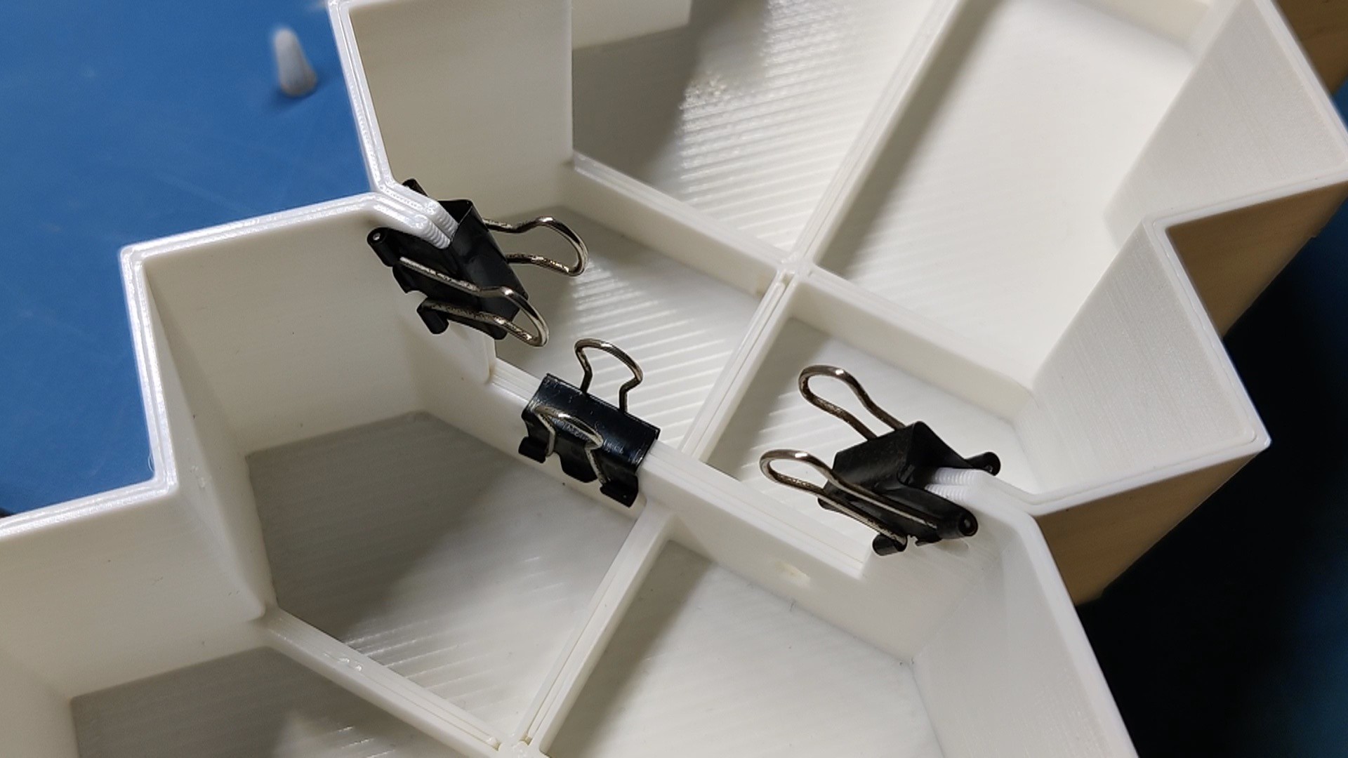
The Sword's Blade part is assembled first by applying super glue on one side of it. Next, in order to maintain a firm grasp between the two components, we attach the second part to the first one by using paper clips to join the two.
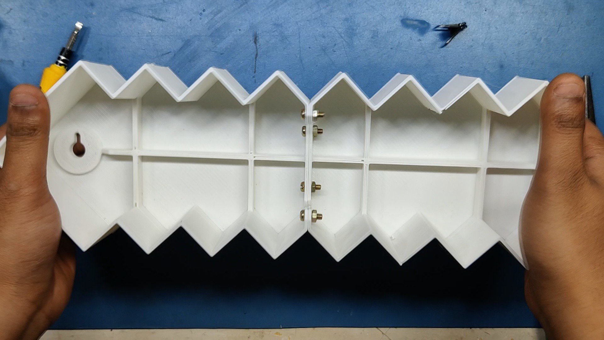
After letting the superglue cure for half an hour, we fastened four M3 nuts and bolts to the holes on each component. This kept the two pieces attached.
Following that, the cross-guard assembly and the handle part are attached to one another using superglue. Paper clips are then used to firmly hold the two pieces together, and four M3 nuts and bolts are used to fasten both assemblies together.
Using the same procedure, we were able to finally link the sword's blade assembly to the cross-guard handle assembly.
5
Adding LED Board inside Base
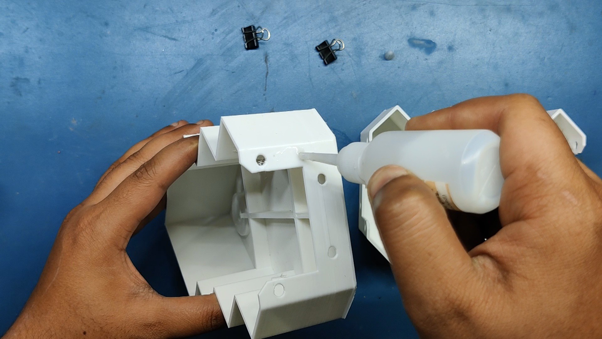
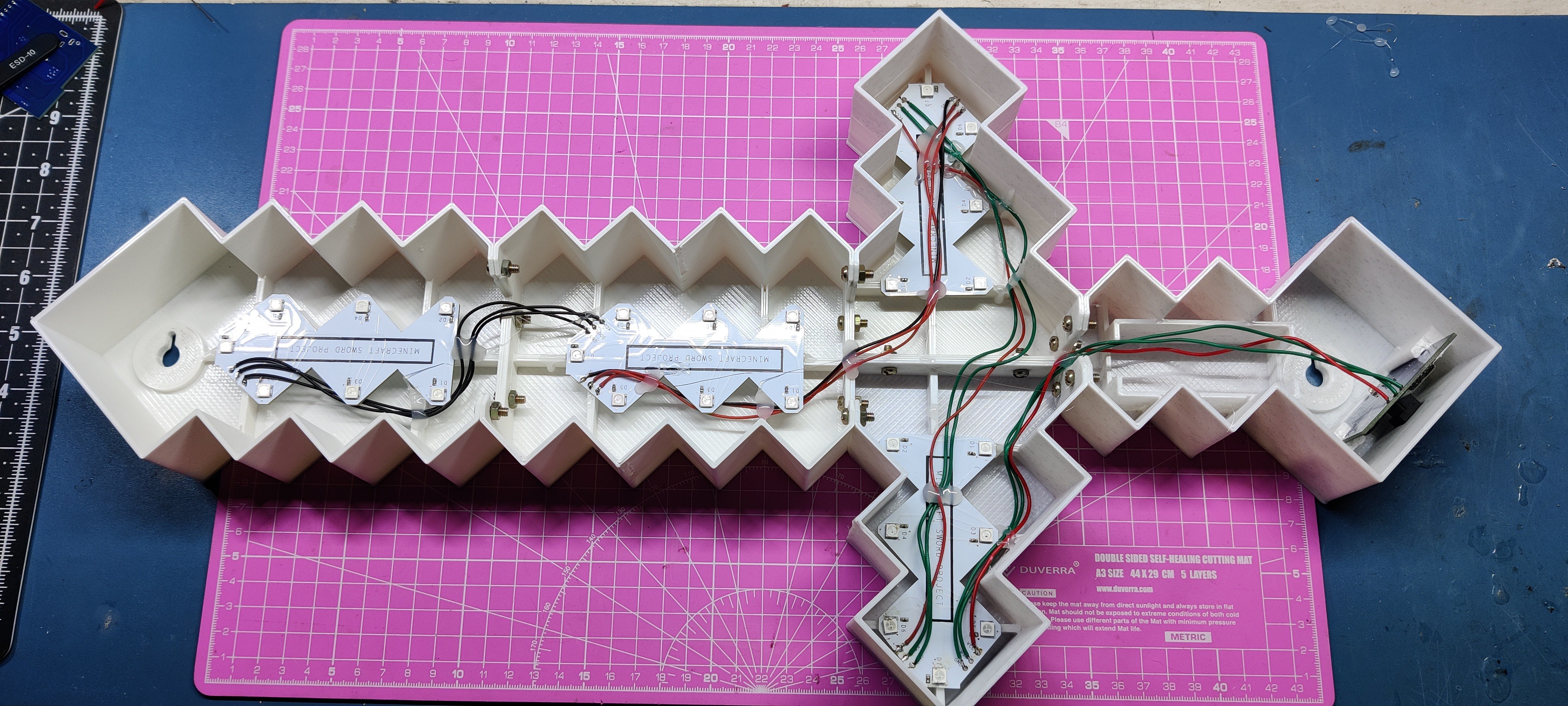
After assembling all parts of the sword together, we start the LED board placement process, which starts by adding the LED board inside the sword blade section first.
We use hot glue to secure the LED board in its place.
We add the LED board to all sections of the sword except the grip section.
6
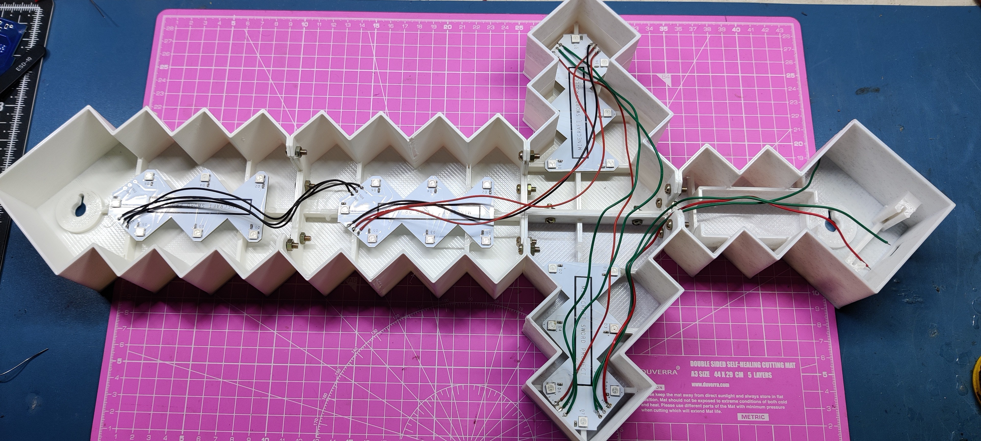
Wiring Process
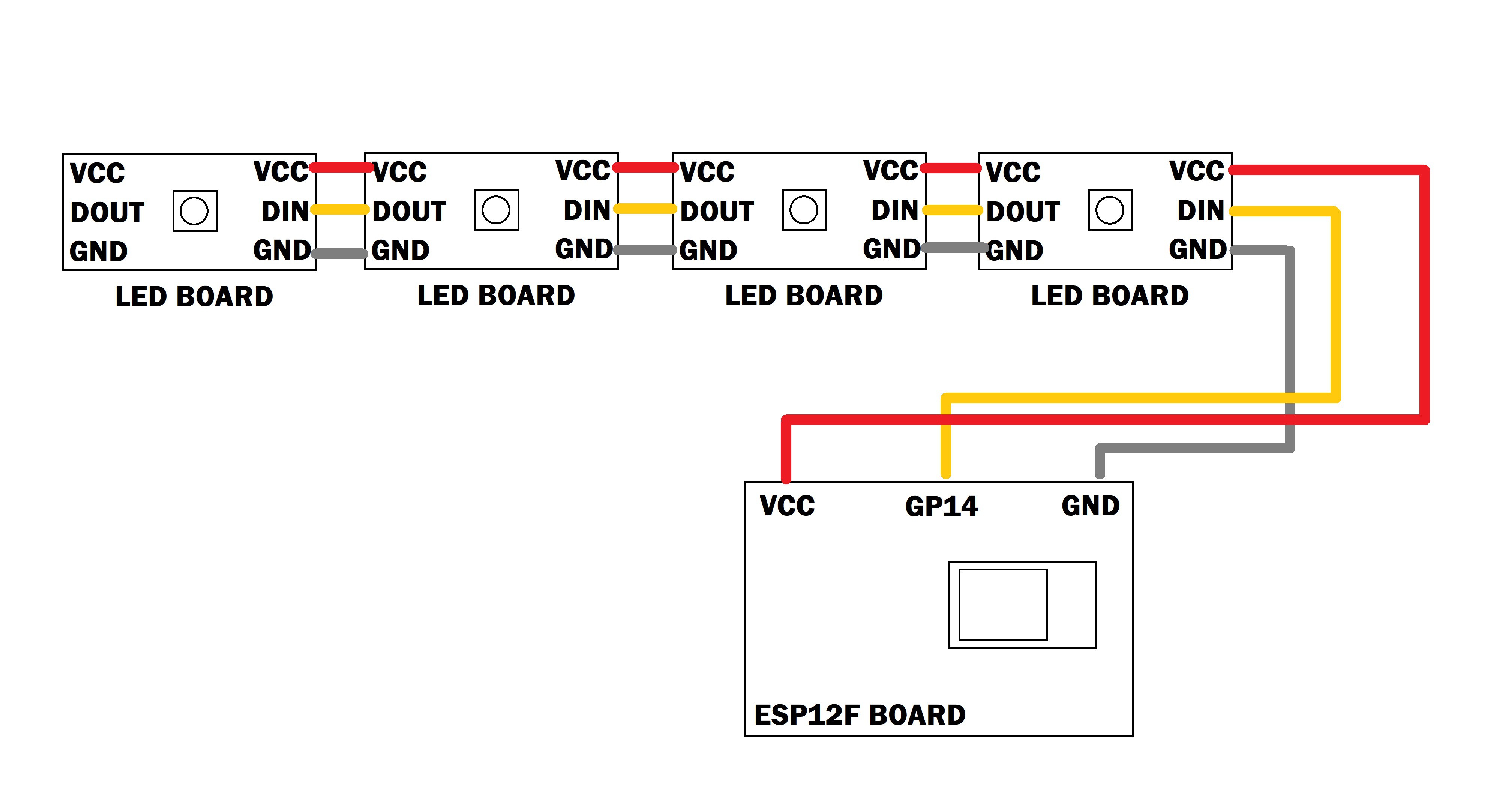
We begin by connecting all of the LED boards' VCC and GND in parallel with one another as specified in the wiring schematic.
The first LED board's Dout is then connected to the second LED board's Din, the second LED board's Dout is connected to the third LED board's Din, and finally the third LED board's Dout is connected to the fourth LED board's Din.
The Din of the first LED board is attached to the GPIO14 pin, and the VCC and GND are connected to the circuit's VCC and GND.
The wiring has been completed.
7
Final Assembly Process
In the final assembly stage, we first slide down the main circuit in its place, modeled inside the lower grip part.
The bundle of wires inside the body is next secured using hot glue; this procedure is done for wire management.
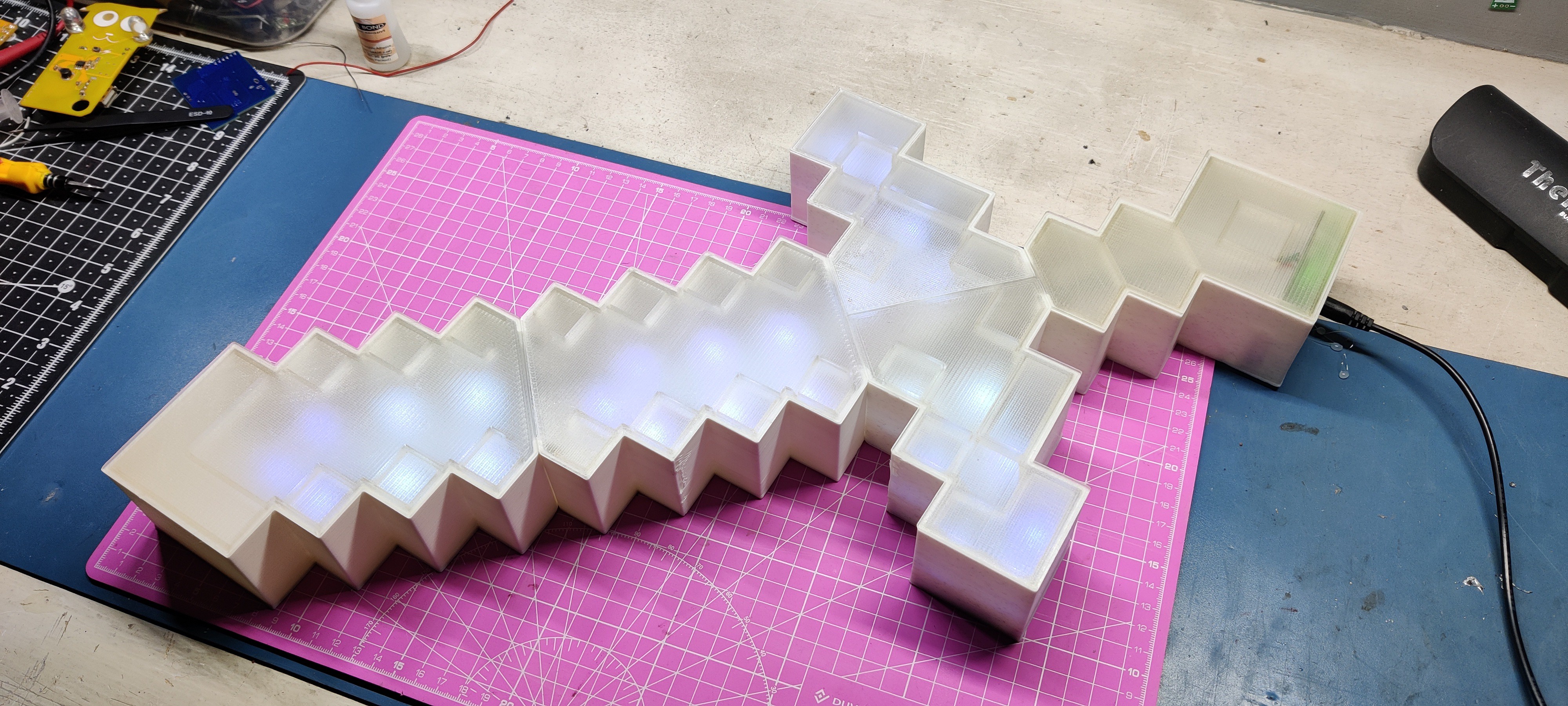
We take the lid portion and place it on top of the assembled sword, Two parts fit perfectly because there is less tolerance between the inner walls of the two parts, this is also called pressure fit.
One by one, we set each lid in its proper place, and the assembly is now finished.
8
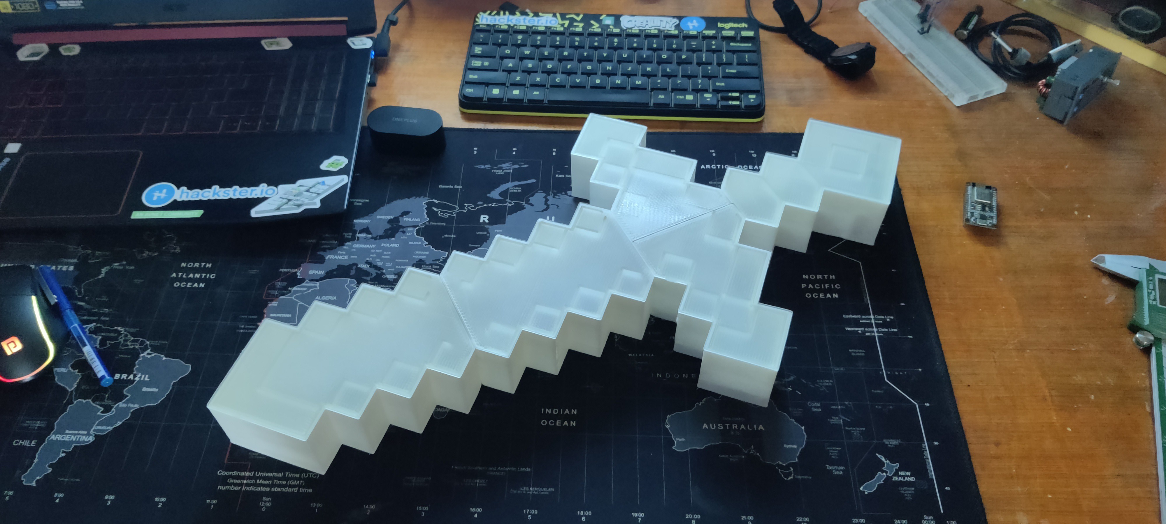
RESULT
This is the end result of my little build: a functioning, illuminated, life-size Minecraft sword that I built from scratch using 3D printed parts and custom PCBs.
We are using a barrel DC Jack to USB Port cable that is connected to a 5V 2A power source to power this system.
By using two nails, we were able to mount this setup on a wall thanks to the keyholes made during the model design process.
The best thing about this project was how the parts were printed with a small 3D printer and divided into smaller printable bits so that anyone with a small printer could easily build it.
Overall, this project is complete and needs no further revisions.
A special thank to PCBWAY for supporting this project; visit them to get a wide range of services, including CNC and PCB services.
 Arnov Sharma
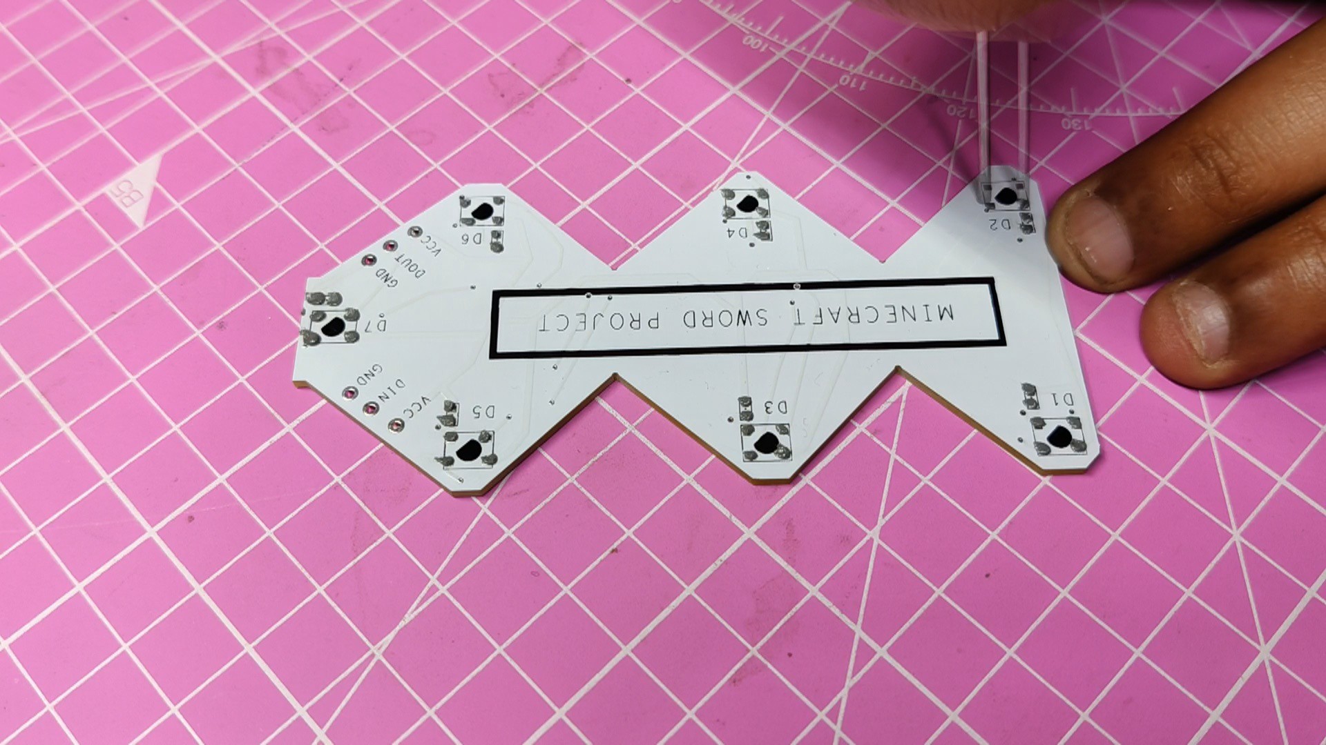


Discussions
Become a Hackaday.io Member
Create an account to leave a comment. Already have an account? Log In.