While trying to work out how the lightsaber would be powered, I found out that the LED strip consumed 70mA even when all of the pixels were off. Since the plan was to program the lightsaber to go into a low-power mode if it was inactive, this presented a problem. Even if the Nano and the audio amplifier were completely shut down, the lightsaber would still consume power until it was switched off. This also would have required a more expensive switch, since the switch would have to be able to switch the full current of the LEDs.
To fix this, I added a MOSFET which could turn the power to the LED strip on and off. I also separated the LED and Arduino/amplifier grounds. This allows the Arduino to be powered through the protection circuit on the battery charger board and through a cheaper, lower-current switch and the LEDs to be powered directly from the battery. If the battery protection circuit cuts off power to the Arduino, or the user opens the switch, then the MOSFET turns off and the LEDs are also disconnected.
A simplified schematic is shown below. A full schematic can be found on this project's Github page.

Two level shifter circuits were required to make this change work. If the gate of the MOSFET were connected directly to an output of the Arduino, then when the Arduino is switched off (either by the user or the protection circuit), the ground of the Arduino circuit would float up towards Vcc, and so would all of the outputs. This would cause the MOSFET to turn on whenever the Arduino was off, defeating the purpose of having a MOSFET in the first place. Thus, I added a level shifter circuit consisting of Q7 and the supporting resistors. When the /SW output goes low, Q7 turns on, supplying voltage to the gate of the MOSFET and turning it on.
The second level shifter circuit consists of D4 and R12. This ensures that the voltage on the DATA output to the LEDs is not negative with respect to the LED ground.
Finally, I added C7 to fix an issue with the V1 PCB, where switching noise from the LEDs coupled into the audio amplifier.
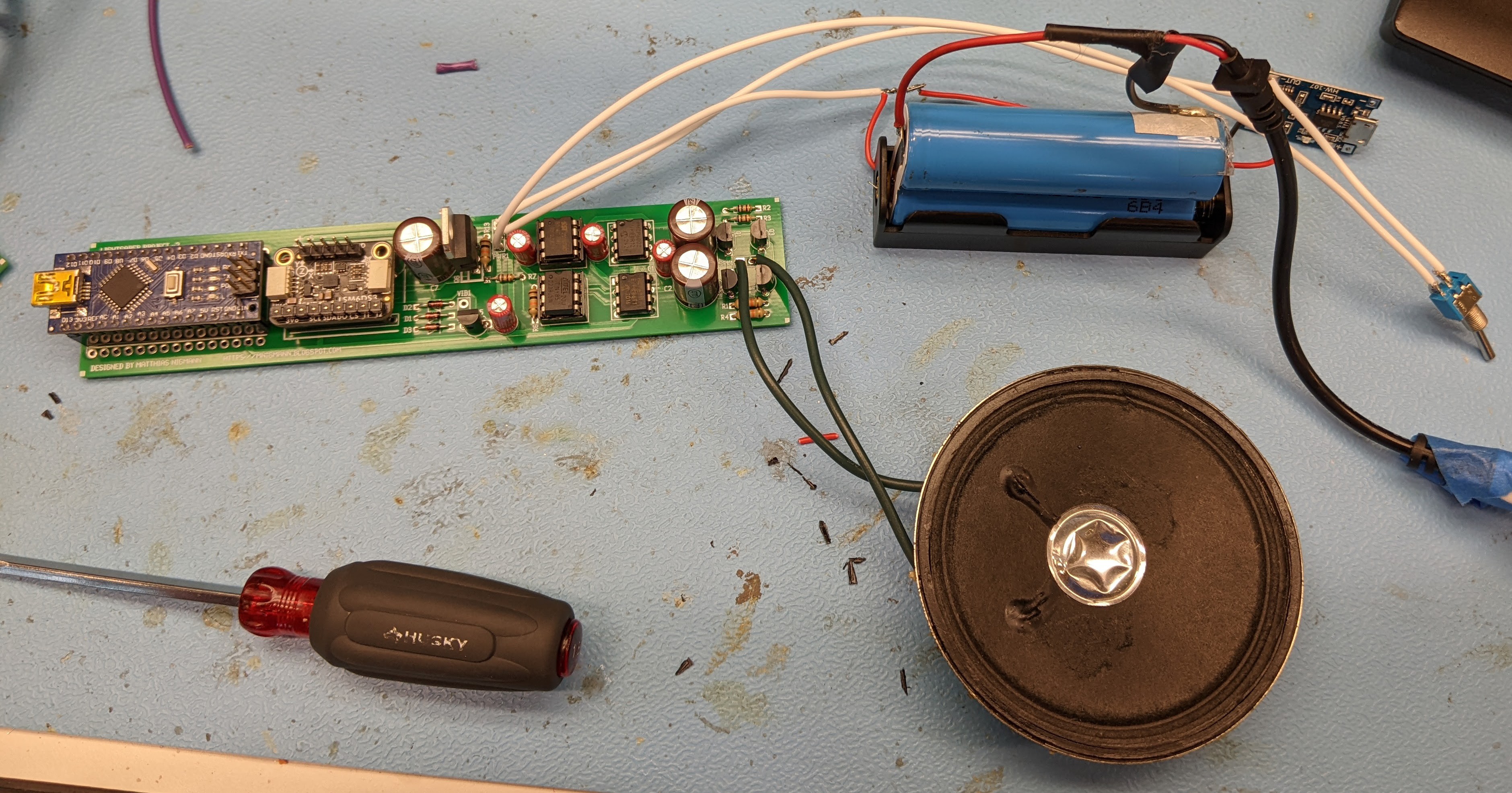
I updates the PCB design to reflect these changes. To fit in the new components, I had to rearrange the audio amplifier to make it smaller. The assembled V2 board is shown below:

Discussions
Become a Hackaday.io Member
Create an account to leave a comment. Already have an account? Log In.