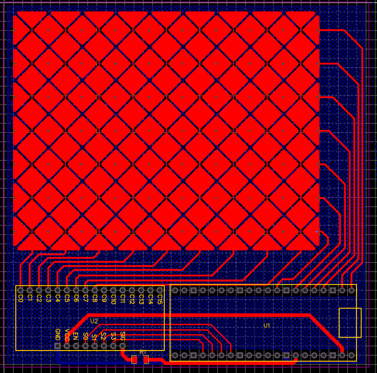
Heya! So, in the spirit of sprinting so fast that I forgot all (two) rules of good PCB design that I ever knew, I sat down some time last week and drafted the very first PCB design for the project. Ain't she a beauty?
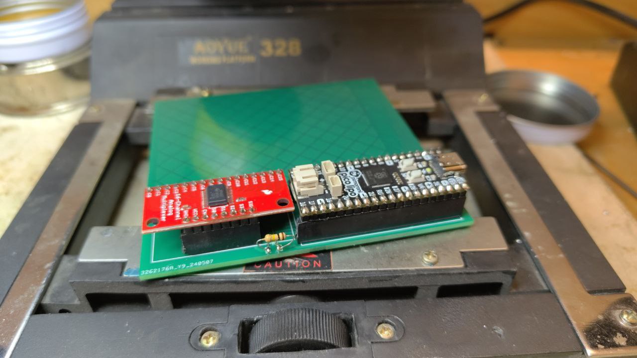
...I don't remember much of what has followed, but somewhere between 4 and 5AM I must've ordered it into production because mere 4 days later it showed up at my doorstep. Somewhere between those two events I started writing code for it, which is now up on the Github along with the schematic-PCB-notes and everything. Anyway, with the board all starry-eyed and begging to be soldered, felt only fair to oblige:
---------- more ----------
Now, see that suspiciously proud R1 between SparkFun's CD74HC4067 breakout board's "SIG" and Pi Pico's ADC? Yeah, that's a 100kOhm resistor that SHOULD NOT BE THERE. What should have been there were 9x 100k resistors pulling the RX lines down to the ground to discharge them gracefully between scans but oh well - first board, first botch. It's the circle of life, a constant, much like the unrelenting march of entropy.
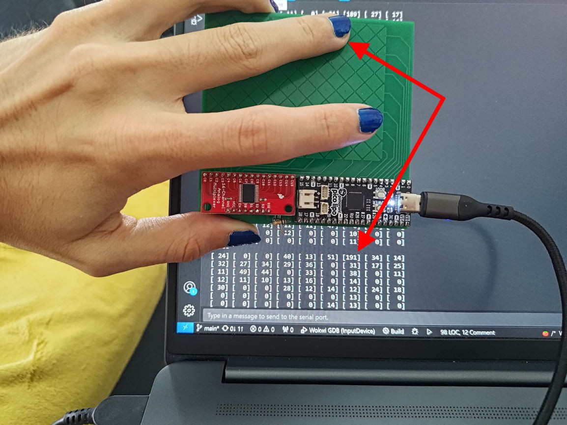
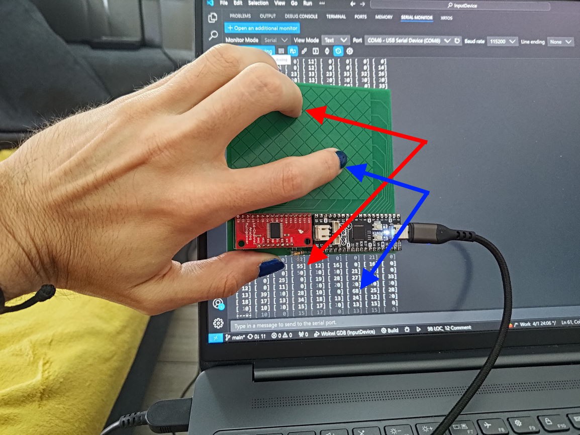
So you might be asking - Tau, how in the world does it work, even after the ad-hoc fixes? BADLY. The answer is it works badly. But it works!
MULTIPASSPORT ahem, multi-touch. Yes, there's a whole host of issues with it - I had to jumper around that R1, I had to add those missing draining resistors; there's no buffer for ADC's input and remember, the plan was to swing TX lines with 10MHz signal, and ADC sampling takes whopping 2us (500ksps doesn't seem so fast now, does it?) - hello aliasing and weird levels and shit! But that's not the point, the point is that even with this smoothbrain attempt it manages to output something plausible. And the good news are that I now have a better idea of what it's gonna take to turn this into an actually usable hardware!
Next time on "internet person attempts to wrangle fiddly pixies":
simulating RX line read-out circuitry!
proper-er circuit design! With drains, Op-Amp buffer to preserve signal integrity, buffer line before ADC to integrate the signal for ADC to have easier time scanning it, and maybe even probe points!
smarter, low-level code to do pin-switching in batches to cram the cell scan body into 4us (on default clock)!
tips on how to measure code latency in clock cycles on Pi Pico!
So I had the idea for this project for a whole of 3 days, and you know how sometimes you just... get an itch to do the thing... Well, yesterday I did the thing.
The thing was - run a single-cell button off my Pi Pico (okay, fine, it's Pimoroni's Pico Lipo - but it's pin-compatible so it still counts! And it still has the shitty ADC). I did that, and managed to see a swing of 0.8V - 1.6V between notouch-touch. nice.
Basically, this proves the concept - you CAN swing a line at 10MHz, 25% duty PWM (dear lord whomever made RP2040/'s IO deserves a medal, "PWM on any and all pins? Go for it, we gotchu."), then feed it into ADC, and read back measurable difference between the sensor being touched or not touched.
---------- more ----------
Before we go any further, my basic-bitch code:
#include<stdio.h>#include"pico/stdlib.h"#include"hardware/gpio.h"#include"hardware/pwm.h"#include"hardware/adc.h"intmain(){
// Set CPU frequency to 100MHz
set_sys_clock_khz( 100000, true );
// PWM setup on pin 26
gpio_init( 26 );
gpio_set_function( 26, GPIO_FUNC_PWM );
uint slice_num = pwm_gpio_to_slice_num( 26 );
// Set up PWM clock & wrapping// To achieve 10MHz frequency we divide main clock by 10; but then multiply by 4 so our 4 counts complete a cycle.// "wrap" is inclusive; "chan_level" is at which count we flip the value
pwm_set_clkdiv( slice_num, 10.0/4.0 );
pwm_set_wrap( slice_num, 3 );
pwm_set_chan_level( slice_num, PWM_CHAN_A, 1 );
pwm_set_enabled( slice_num, true );
// ADC setup
adc_init();
adc_gpio_init( 28 );
adc_select_input( 2 );
stdio_init_all();
// Keep the program runningwhile( 1 ) {
constfloat conversion_factor = 3.3f /(1 << 12);
uint16_t result = adc_read();
printf( "v: %f V\n", result * conversion_factor );
sleep_ms( 100 );
}
return0;
}
Clock is dropped to 100MHz to make PWM divider math easier (also, this is a live example of how you can configure your PWM frequency on Pi Pico/RP2040, free of charge!), and other than that there's really nothing to it - pump the TX line, read off RX line. EZ.
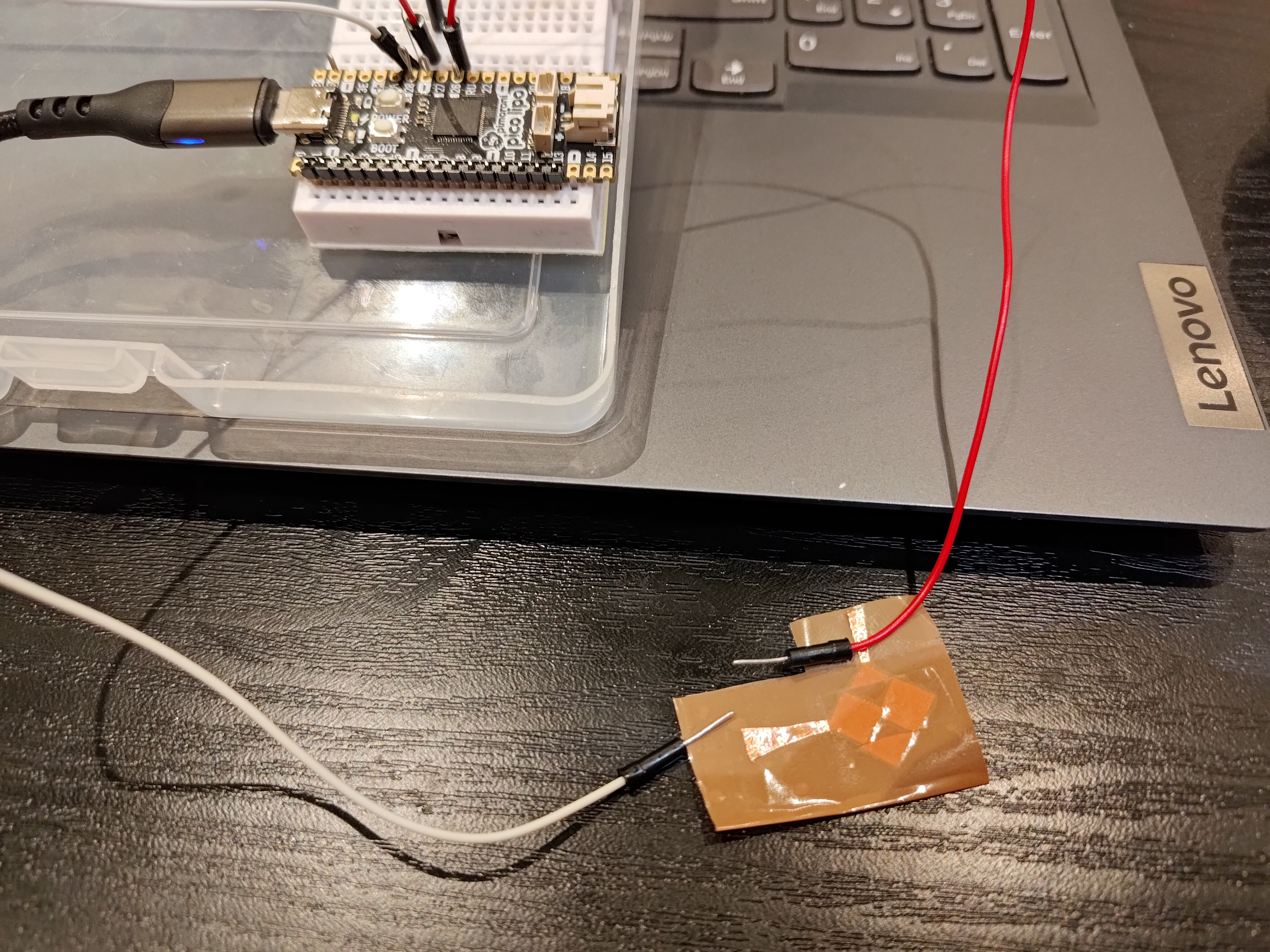
I dunno how much physical time adc_read() takes up, so there's still that unknown (I'll need to find that out so the math can be mathin' for matrix scanning), but we're primed and ready to take it to the next level - scanning a matrix. And for that we'll need a PCB, which should also help with all the uncertainties of my ghetto setup where I'm hand-holding leads to raw-dogged sticky copper foil chopped by multitool scissors :D
 Tykhon