-
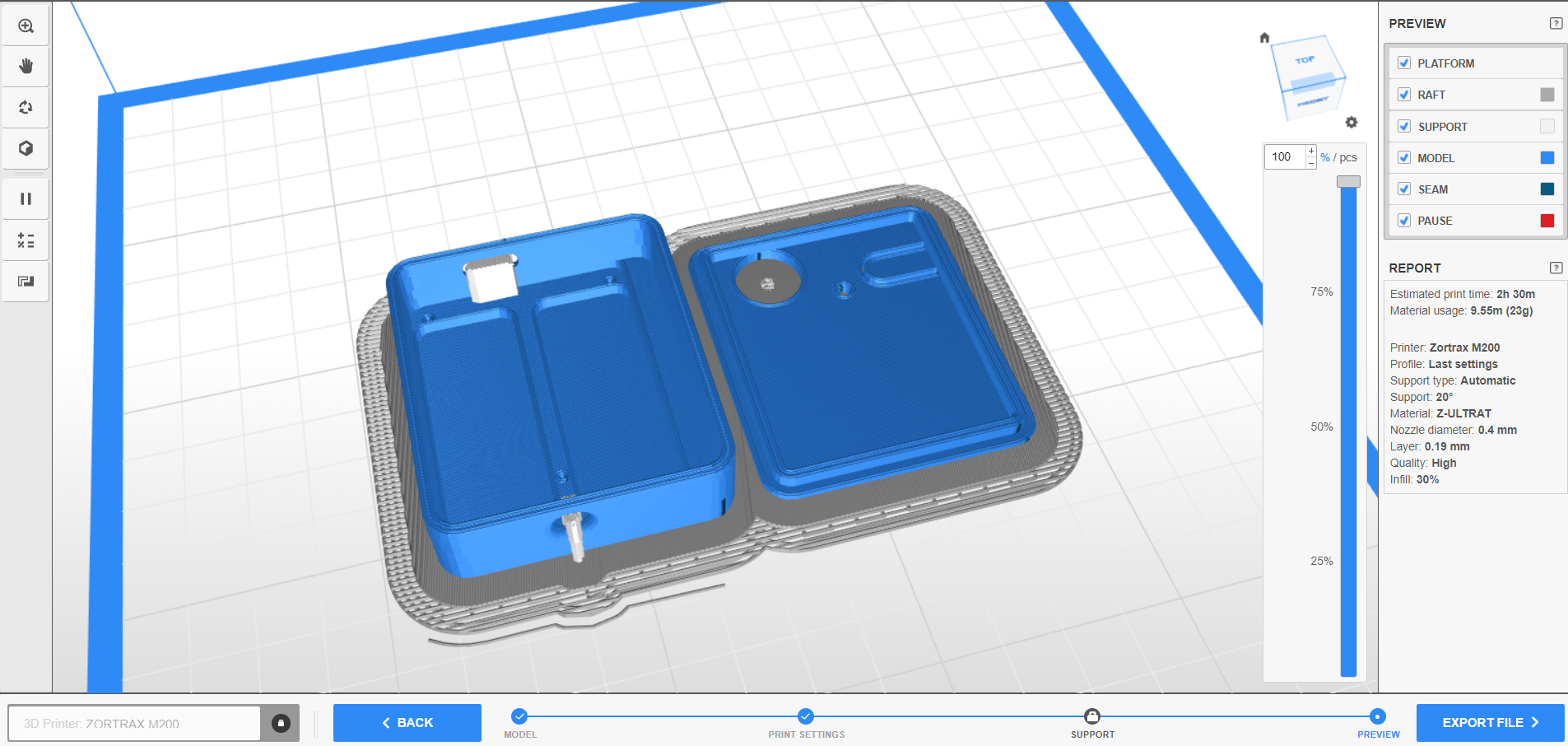
1ENCLOSURE : 3D Printing
Print the two stl files : base and top -
2ELECTRONIC ASSEMBLY
Individually prepare the components :
![]()
- Solder 2*6 headers on the ADAFRUIT QTPY RP2040 (pins A1--TX and RX--GND)
![]()
- Solder 2 headers on the 3.5mm jack breakout (pin TIP ans SLEEVE)
![]()
![]()
- Cut two platsic pins under the tactile switch, cut two pins on the switch
![]()
![]()
- Cut two wires : 3.5cm and 4cm
![]()
Solder the components :
- Solder the ADAFRUIT QTPY RP2040 on the protoboard : B1 to B6 and F1 to F6)
![]()
- Solder the tactile switch on the protoboard G1 and G3
![]()
- Solder the 3.5mm jack breakout (F11 and E11)
![]()
- Connect A3 QTPY's pin to RING02 with the 3.5 cm wire, solder
![]()
- Connect GND QTPY's to TIP with the 4cm wire, (J1- J11), solder
![]()
Cut of the excess lenght of the pins
-
3MECHANICAL ASSEMBLY
- Insert the electronic onto the base part
![]()
- Snap the two parts of the enclosure
![]()
![]()
- Insert the electronic onto the base part
-
4PROGRAMING
- While maintain the boot button pressed, plug the QTPY RP2040 in a computer with a USB C CABLE
![]()
- A drive name RPI-RP2 appears
- Drag and drop the UF2 file onto this drive
- The QTPY's reboot, the program runs
- While maintain the boot button pressed, plug the QTPY RP2040 in a computer with a USB C CABLE
-
5USE
- Plug a USB C cable from Assist to a computer or a smartphone
- Plug an assistive switch in the jack port of the assist
- When you press the assistive switch the ASSIST emulate a HID Function
- To change the HID mode, press the ASSIST Mode Button, the color's led change
![]()
Blue : Spacebar Key
red : Return key
yellow : Left mouse click
green : assistive switch is pressed
Assistive Single Switch interface Switch tester
ASSIST is an interface for one assistive switch. Test, play and access
 Julien OUDIN


Discussions
Become a Hackaday.io Member
Create an account to leave a comment. Already have an account? Log In.