-
11Adding Battery
![]()
![]()
![]()
![]()
![]()
![]()
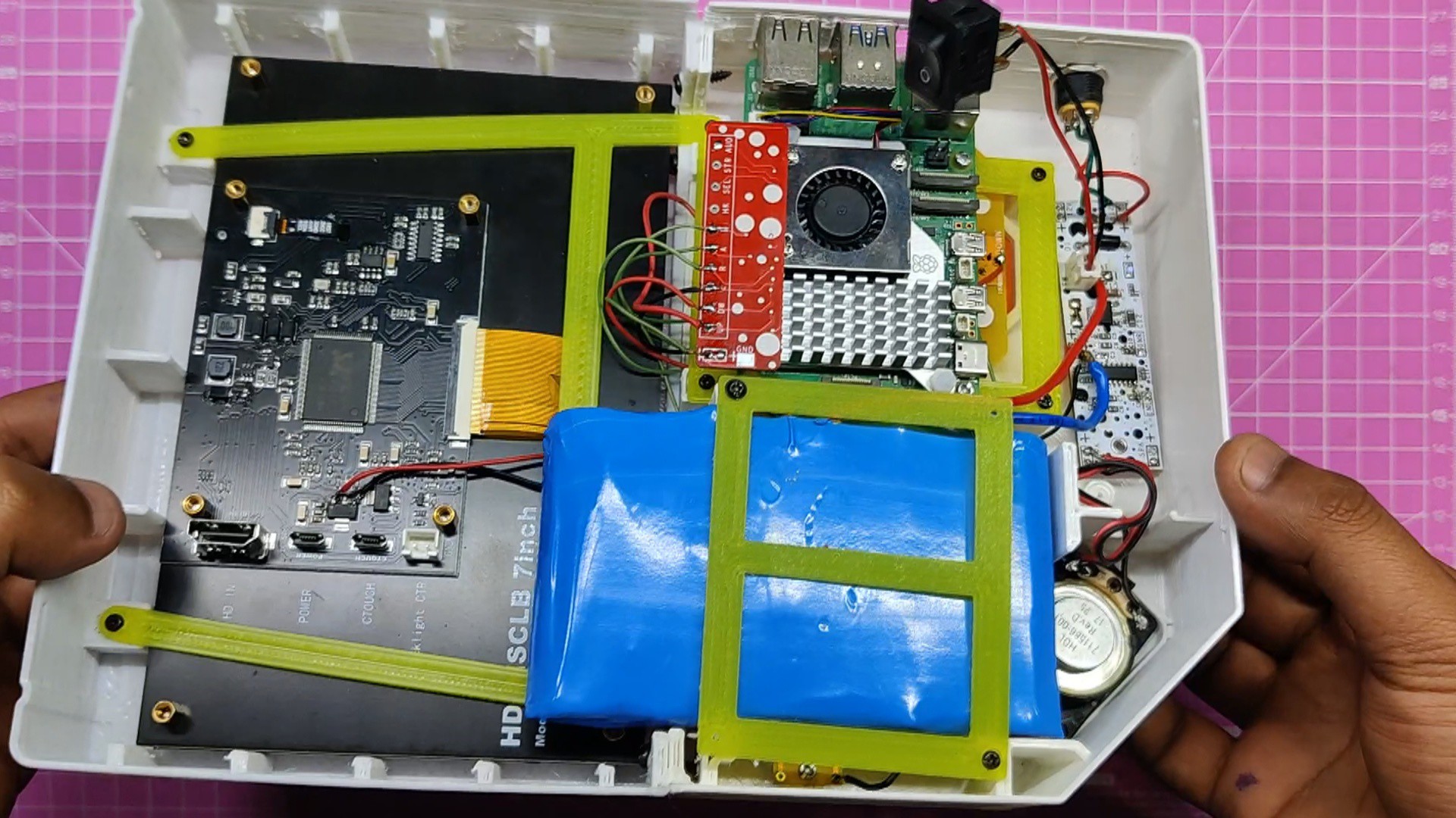
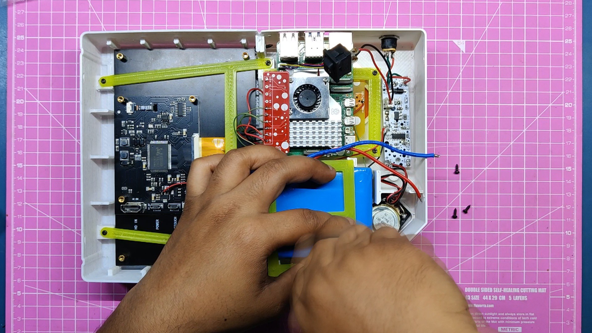
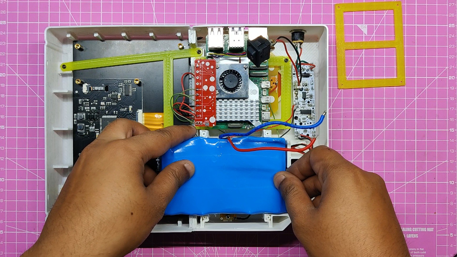
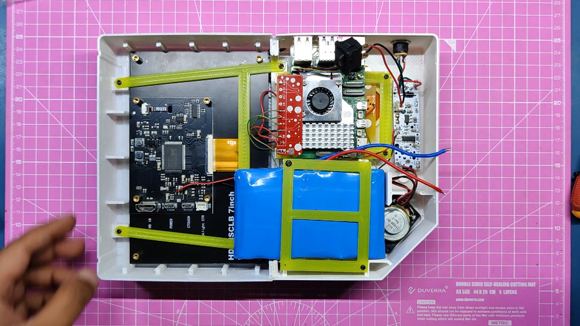
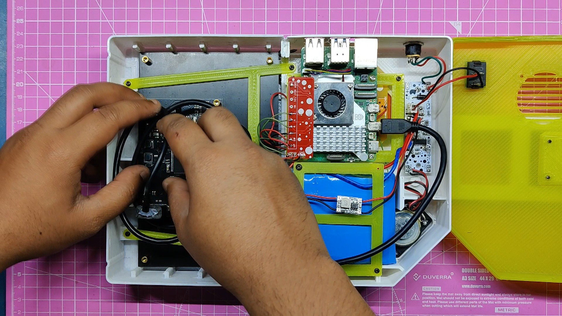
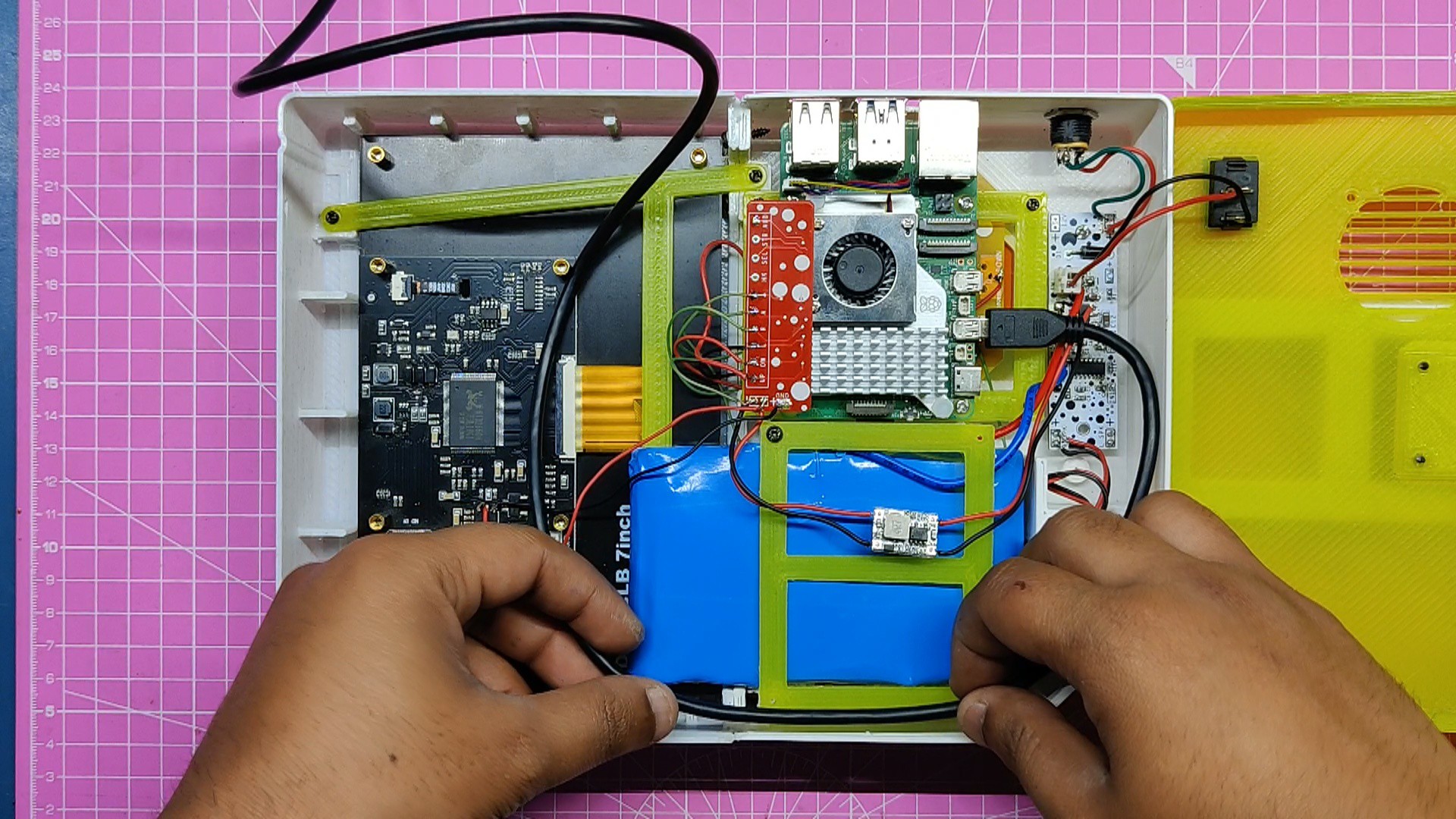
- We have now positioned the battery in its proper location. We have modeled a whole mounting area for the battery, which is made up of ribs that hold the battery in place and support it. These ribs work similarly to the ribs supporting the display.
- The battery is mounted permanently by utilizing a battery clamp, which is placed on top of the battery and secured with four M2 screws.
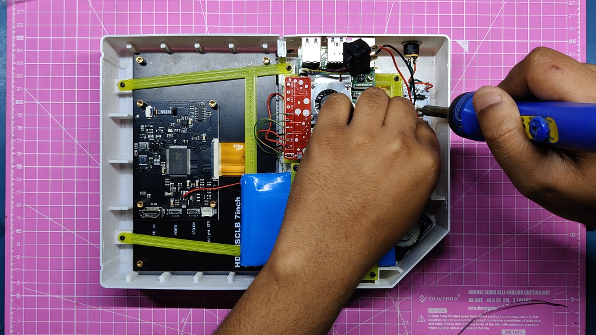
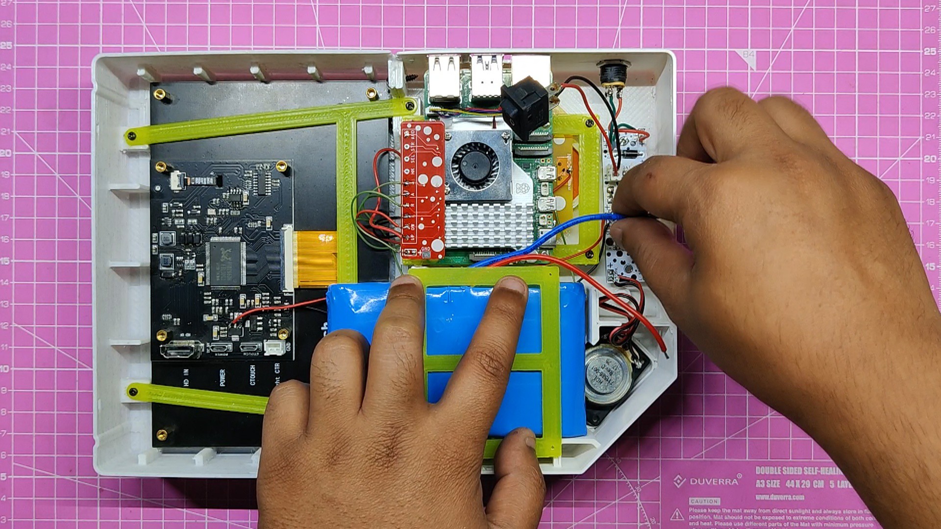
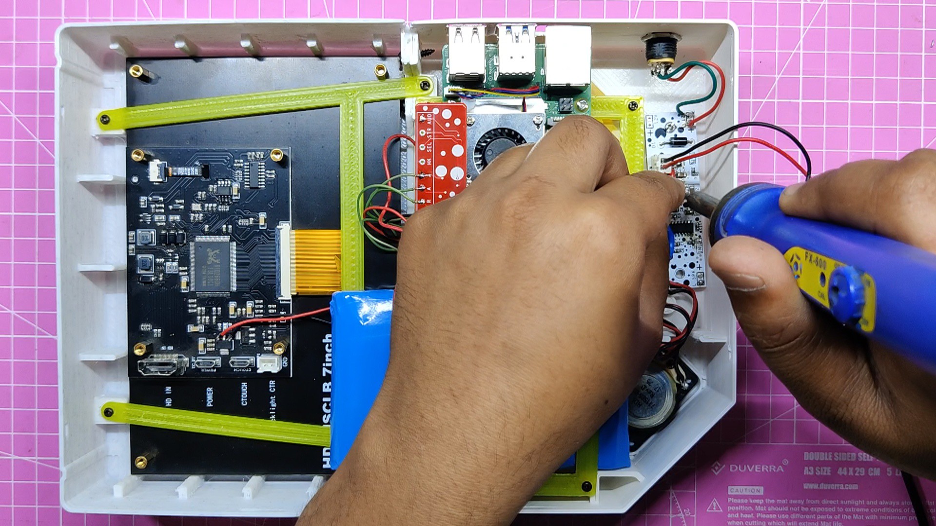
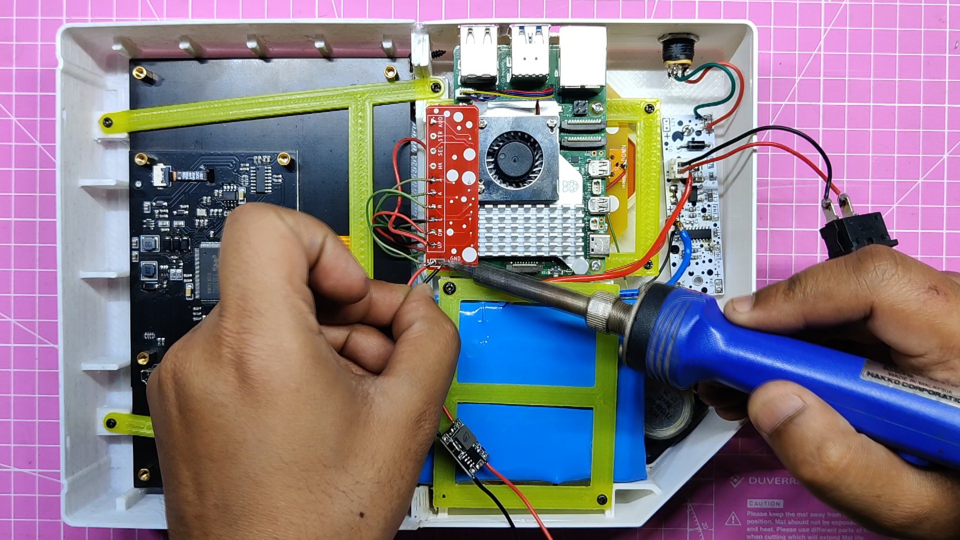
- We attach the battery terminals to the battery connector on the Aduio Board. The power board, which has an AMS1117, an indicator, and a diode for mounting the display and audio section of the board, is also connected to the audio board using a soldering iron.
- Finally, we flip the model over and click the rocker switch, to turn on the display, indicating that the battery assembly was successful and that the AMS1117 is powering the display.
-
12DC-DC Buck Converter
![]()
![]()
![]()
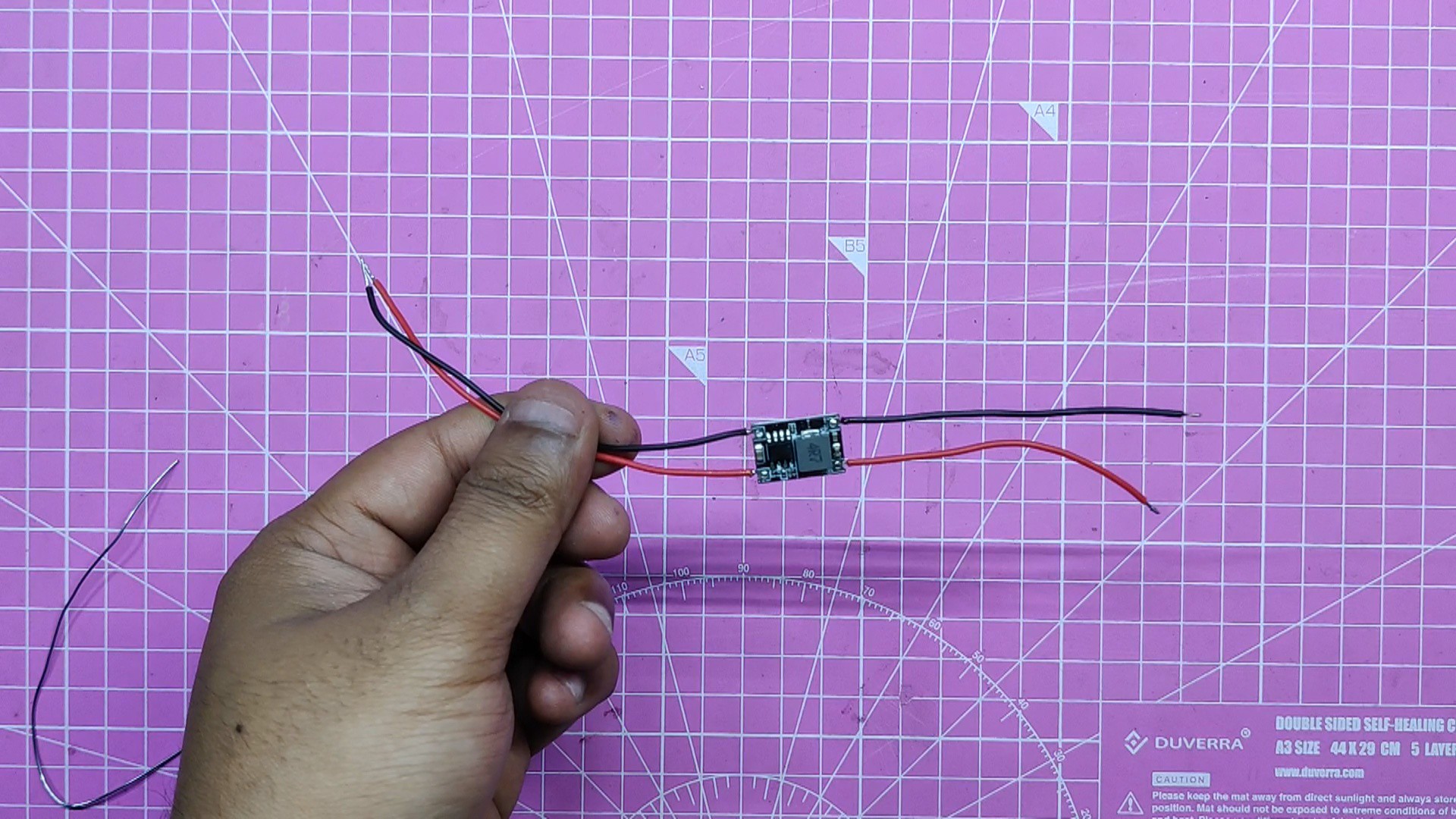
We needed to utilize a buck converter to power the power-hungry Raspberry Pi 5 from a 12V supply, but we did not just need any old buck converter—we needed one with a consistent 5V/3A output. After some research, we chose this sucker, which can provide stable 5V/3A from a 12V to 28V source.
- First, we solder connection wires to the buck converter's input and output terminals.
- Next, we linked the buck converter's input to the audio board's 12V.
- We can toggle power using the rocker switch on the audio board's 12V port, which has a switch between the 12V battery and the 12V con2 connector.
- The GPIO breakout board's output terminals were then connected to 5V and GND, which will power the Pi.
-
13Back Lid: Adding Logo
![]()
![]()
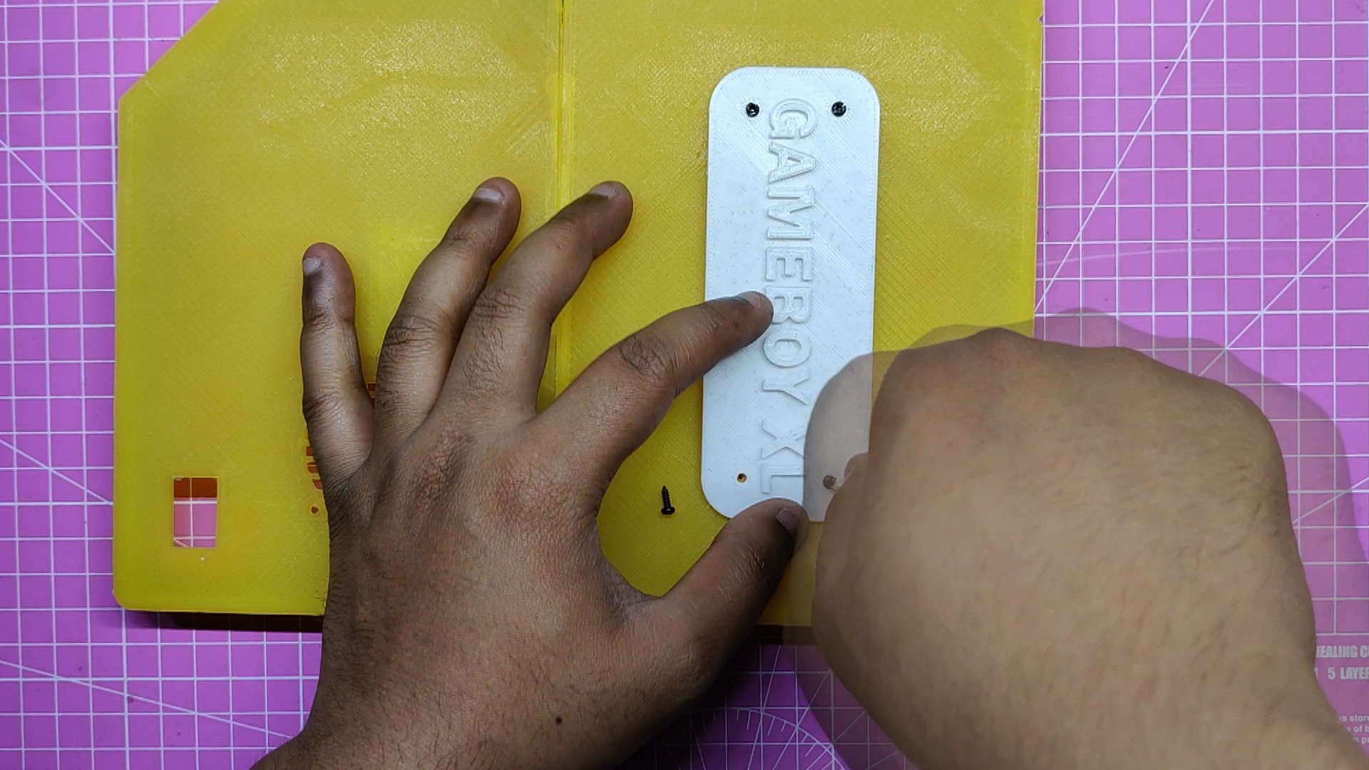
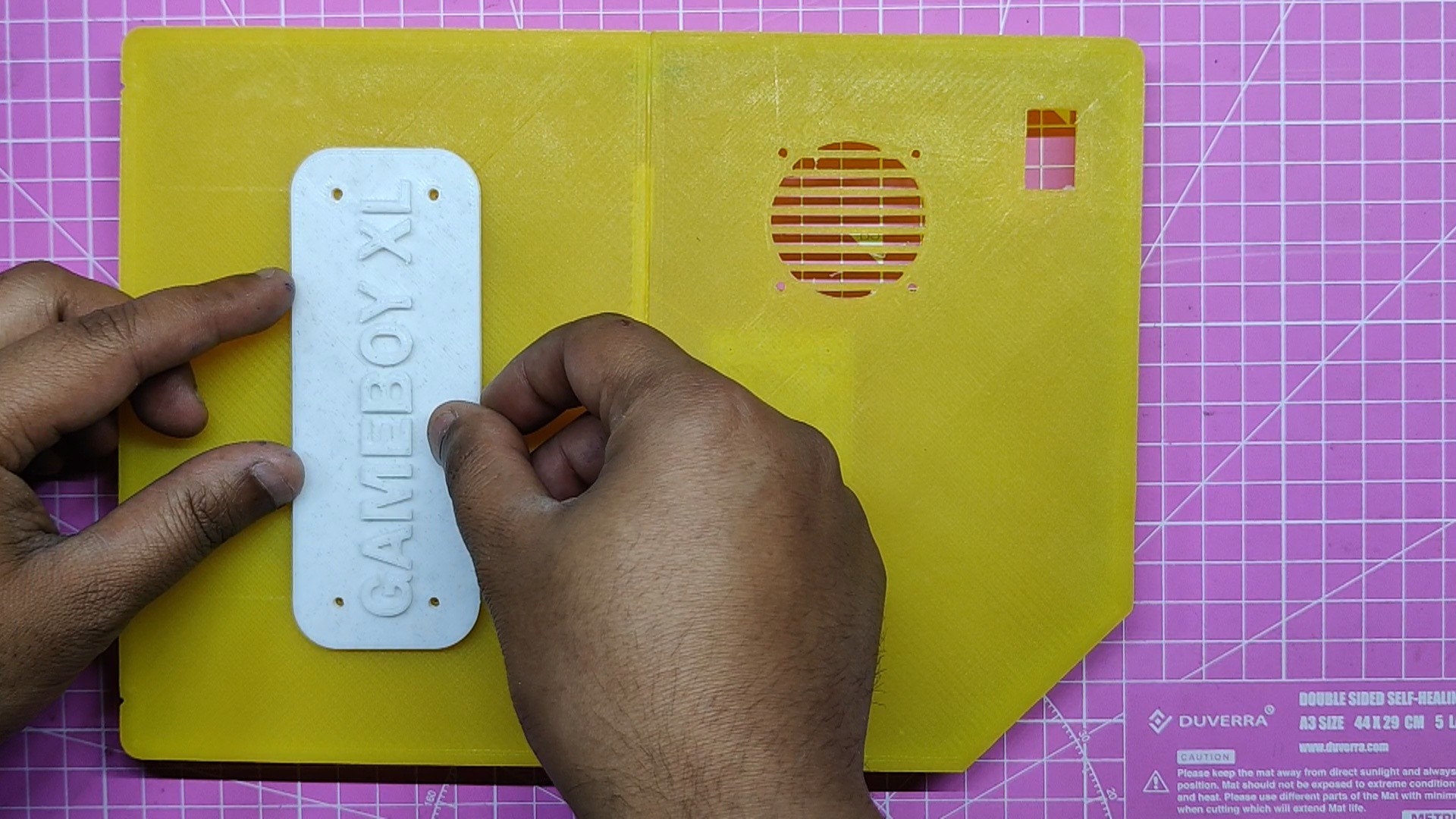
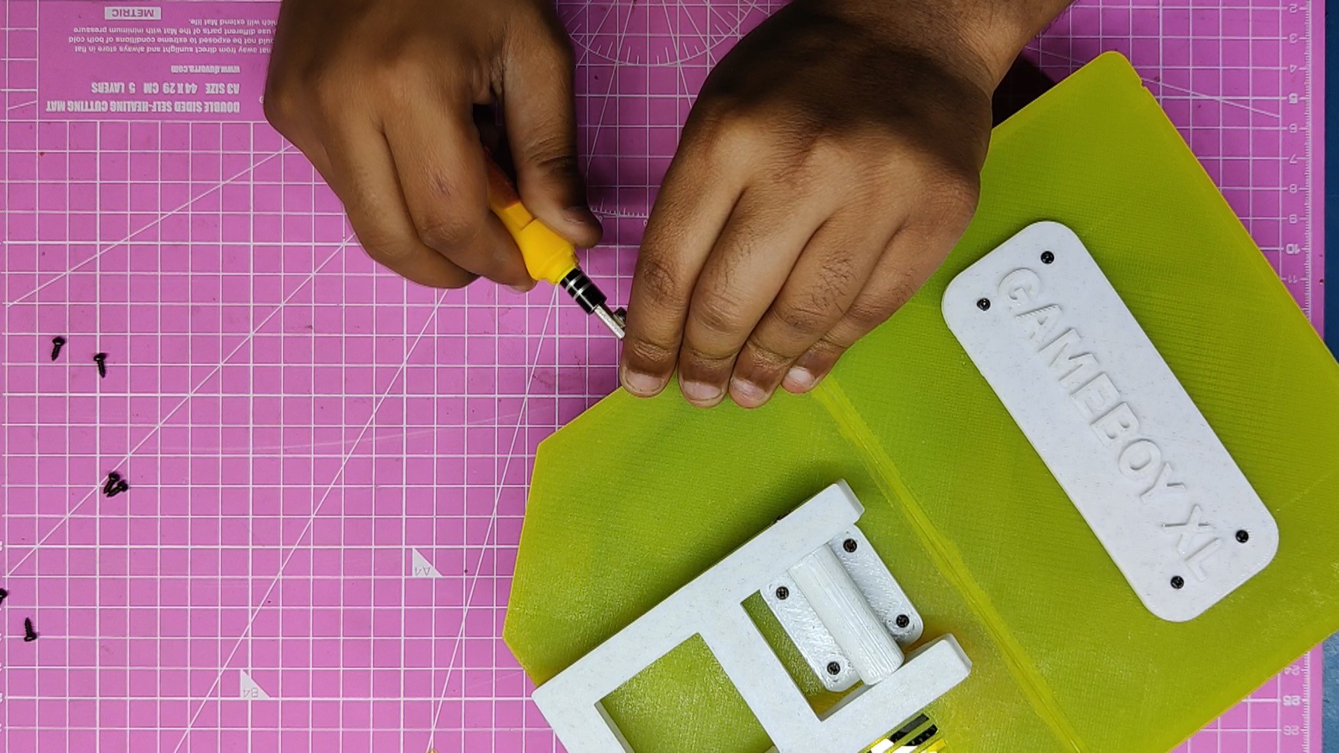
We put the name tag in its place on the Gameboy lid and fasten it to the lid with four M2 screws
-
14Stand Assembly
![]()
![]()
![]()
![]()
![]()
![]()
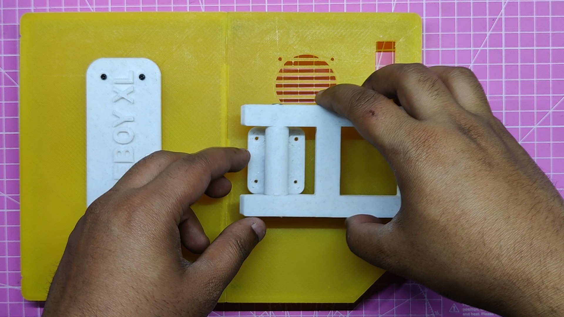
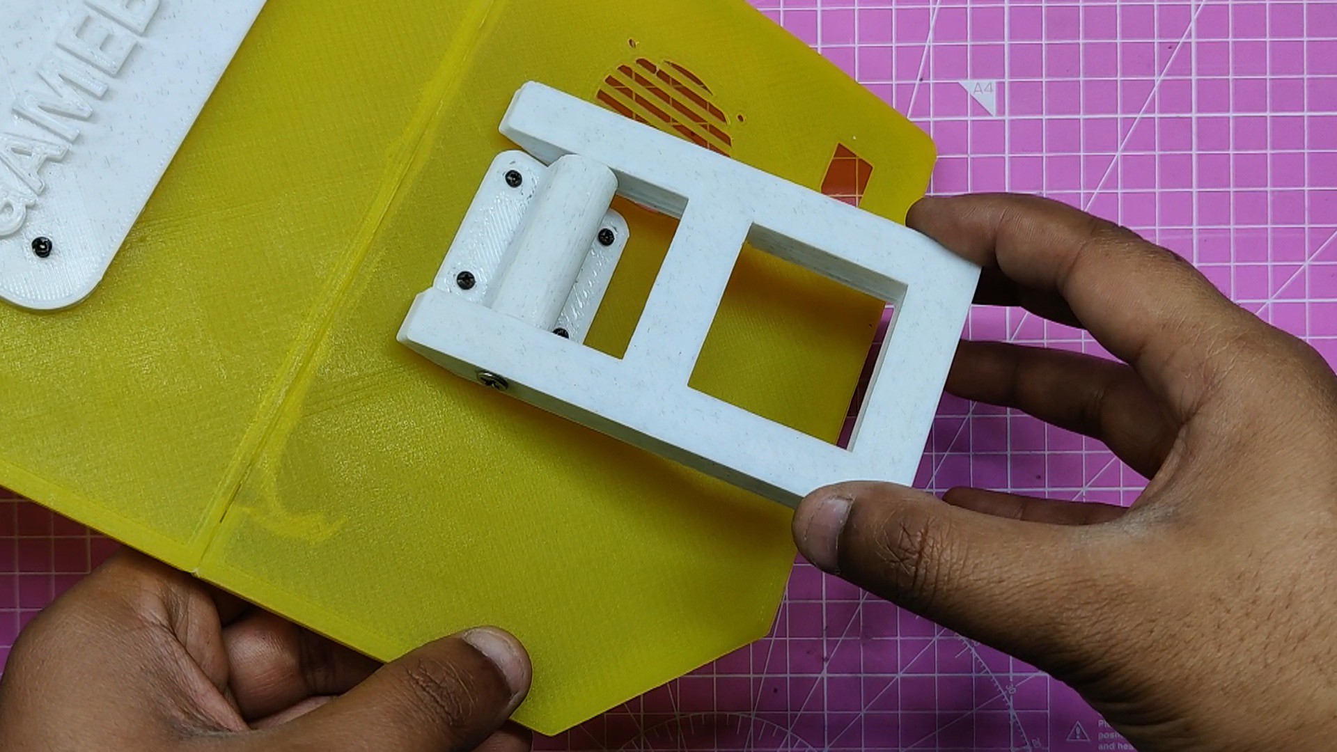
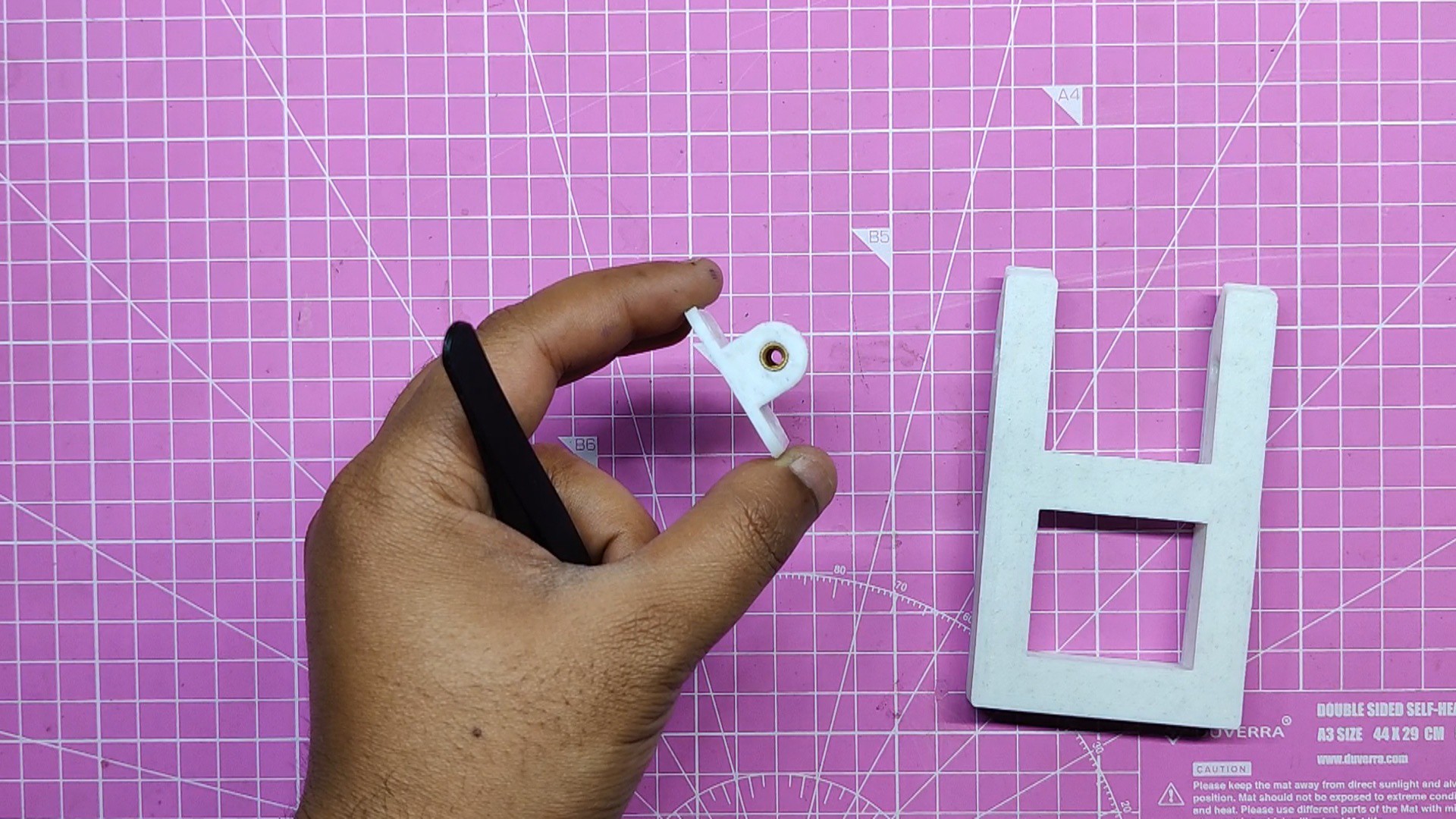
- The stand assembly is the next component, and it is made up of two parts: the stand and the holder section.
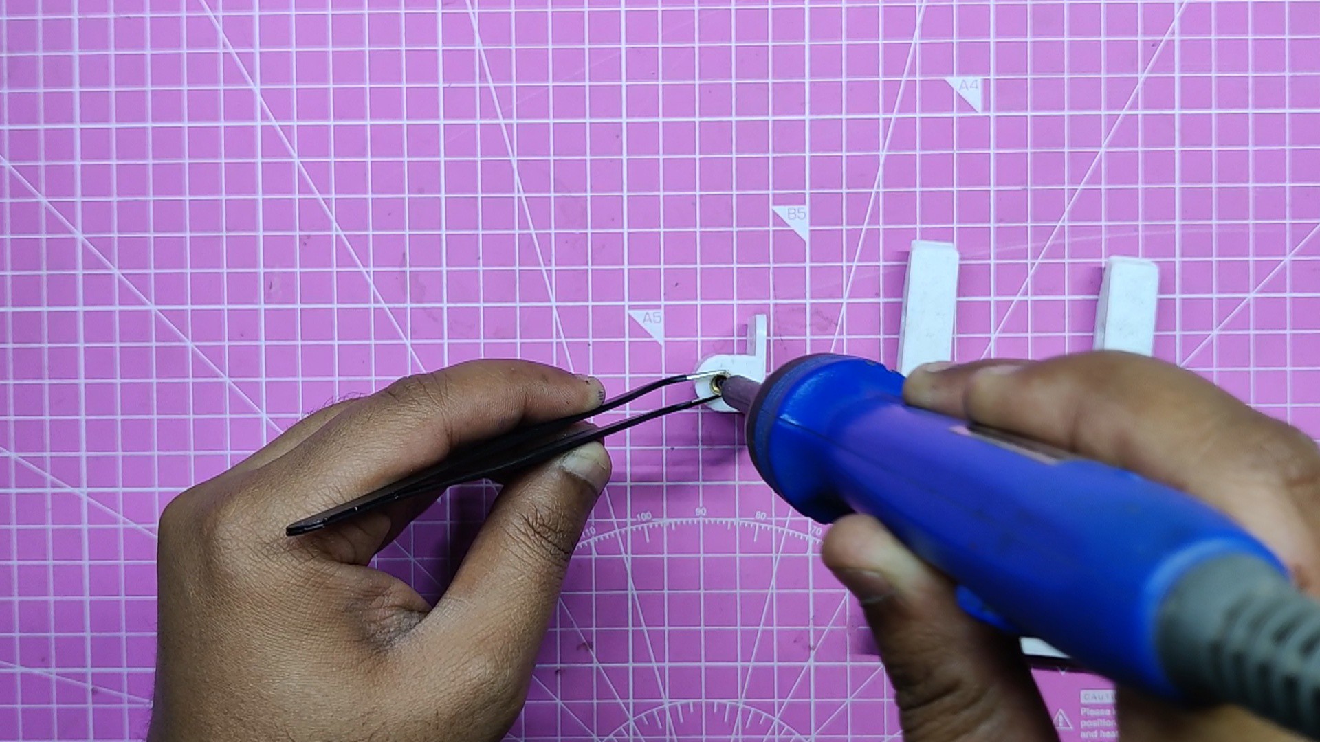
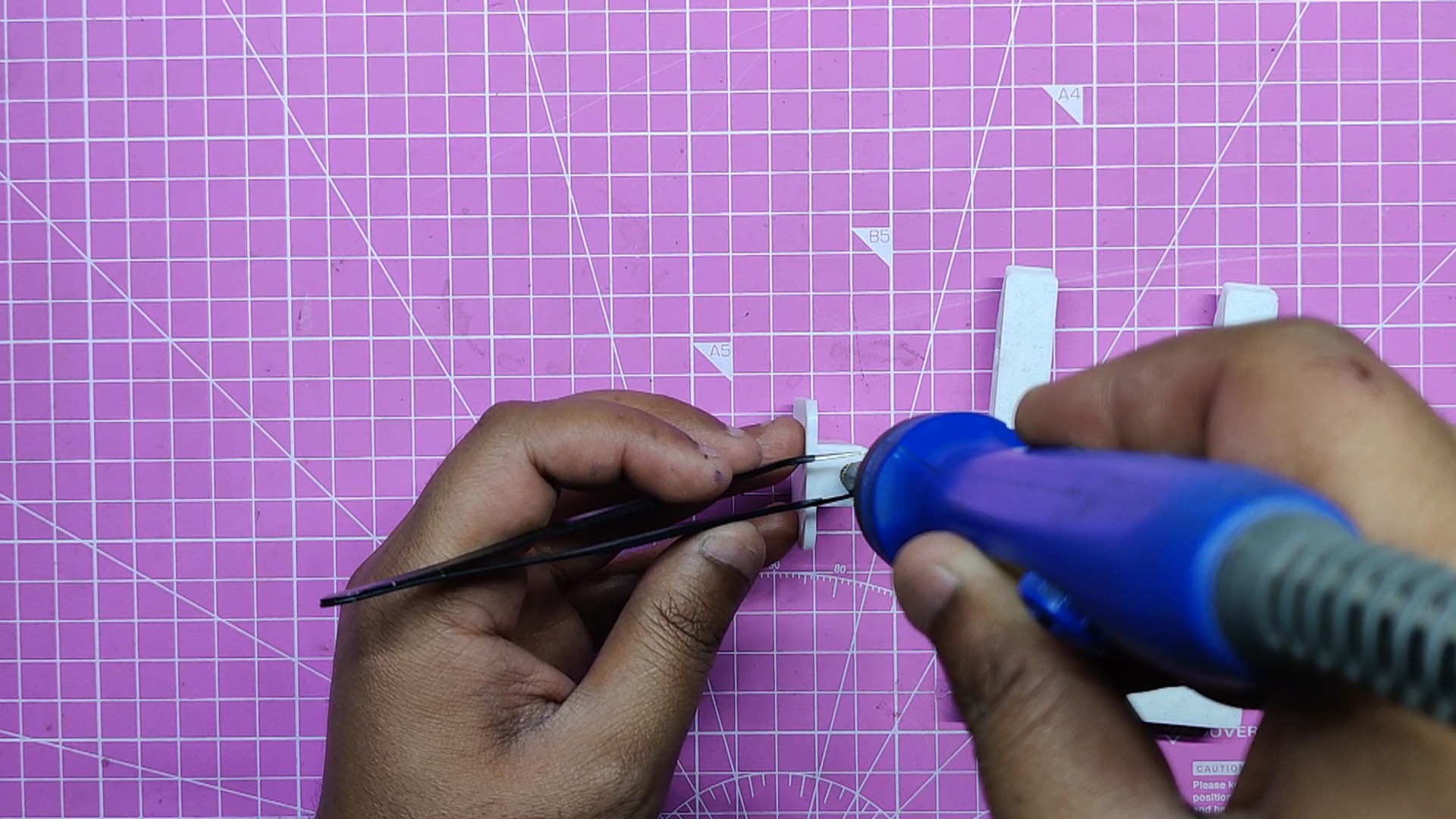
- Using tweezers and a soldering iron, we must first install M3 threaded inserts on both ends. It is recommended to set the soldering iron temperature to 150 degrees Celsius while working with PLA.
- Next, we use two M3 bolts from each side to fasten the stand and holder components together. The M3 bolts attach the two sections together using M3 threaded inserts.
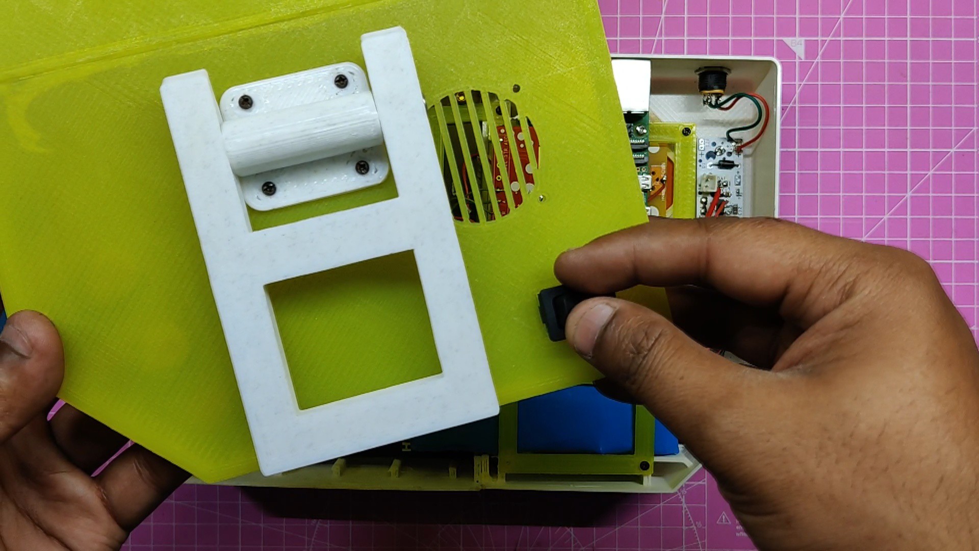
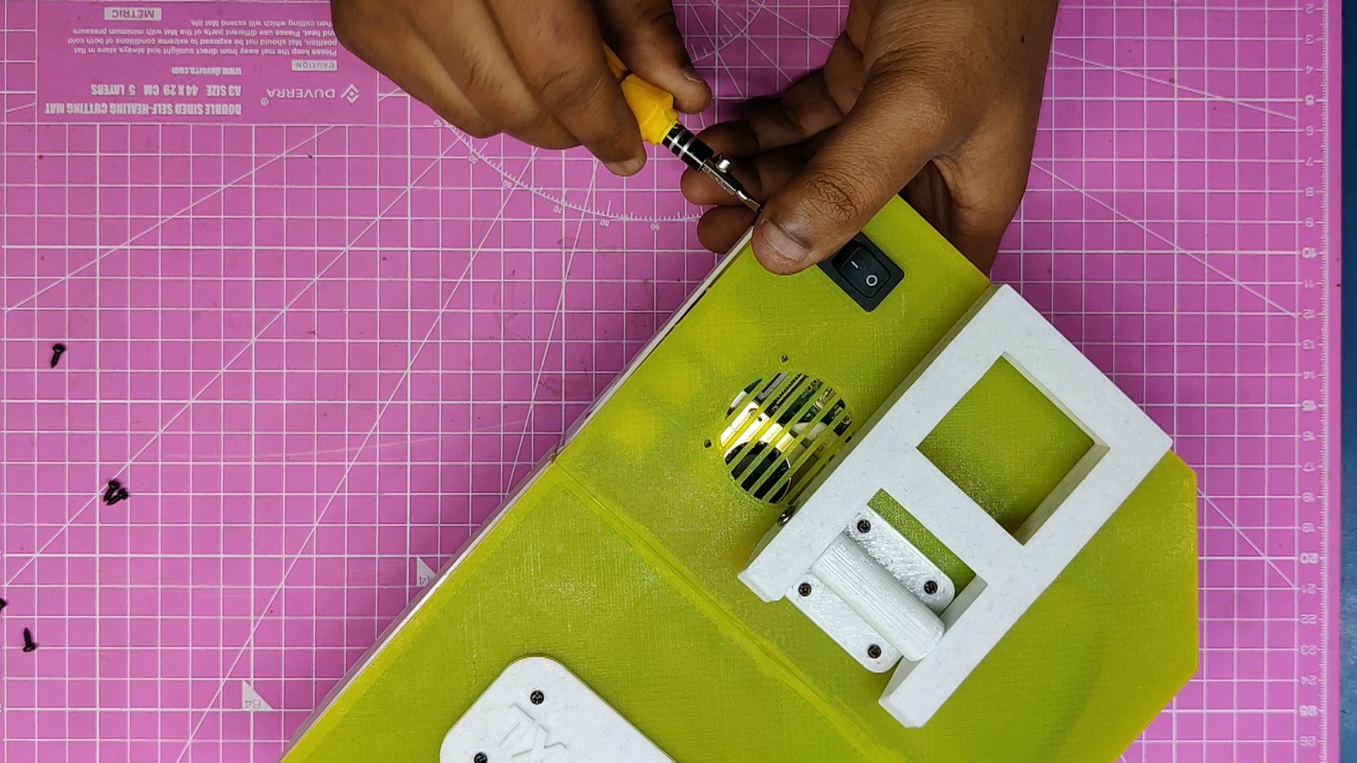
- The stand holder assembly portion is then positioned on the rear side of the lid, and four m2 screws are used to secure the stand part to the lid.
Lid assembly is now complete
-
15Final Assembly
![]()
![]()
![]()
![]()
![]()
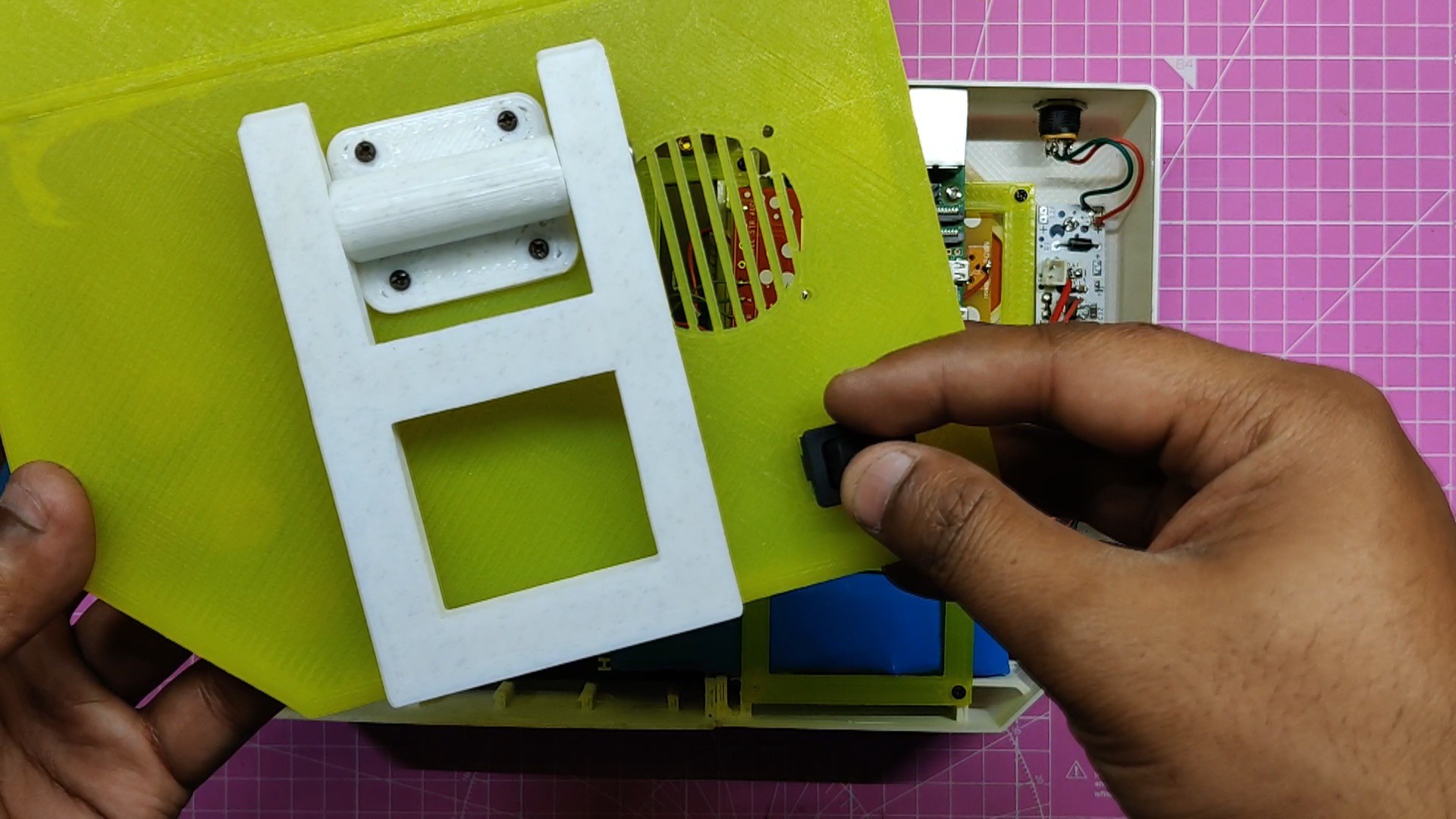
On the lid, we added a Rocker switch in the given slot and then connected the rocker switch with the audio board. This rocker switch turns the setup ON or OFF.
- A standard-size HDMI cable was inserted inside the Gameboy body to link the Pi5 to the display. Since the Gameboy is an XL version, there is ample room within the body, so the space issue was not an issue. Since the flat cable I had was short and we required a slightly longer one, we ended up using HDMI cable. A better solution that may be employed in this situation would be flat cable HDMI ports, which would save a lot of space.
- We place the lid on the back side in its proper location and fasten it to the body with eight M2 screws.
The assembly process was completed.
-
16RECALBOX OS
Gameboy is nothing more than an empty shell with RP5 and other items inside of it without the OS.
The core of this project was the Retro Arch-based RecalBox game emulator operating system. RecalBox is a great OS to use because it has a lot of games pre-installed. Installing this OS on the Pi allows us to play popular games like Doom, Wolfenstein, and Quake right out of the box.
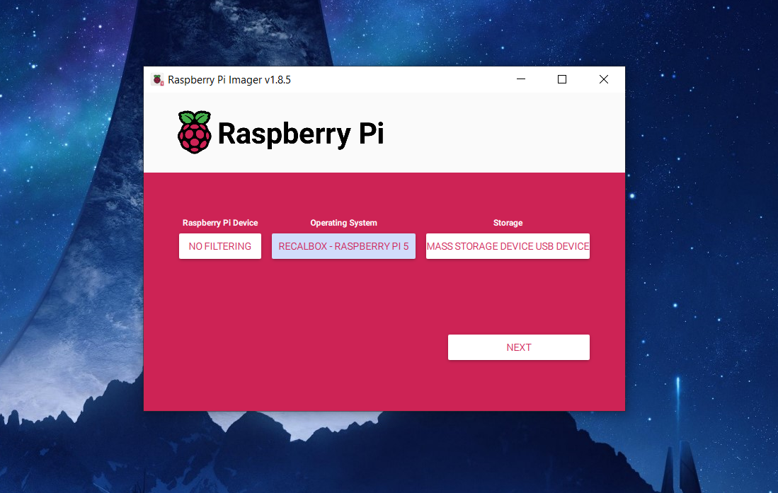
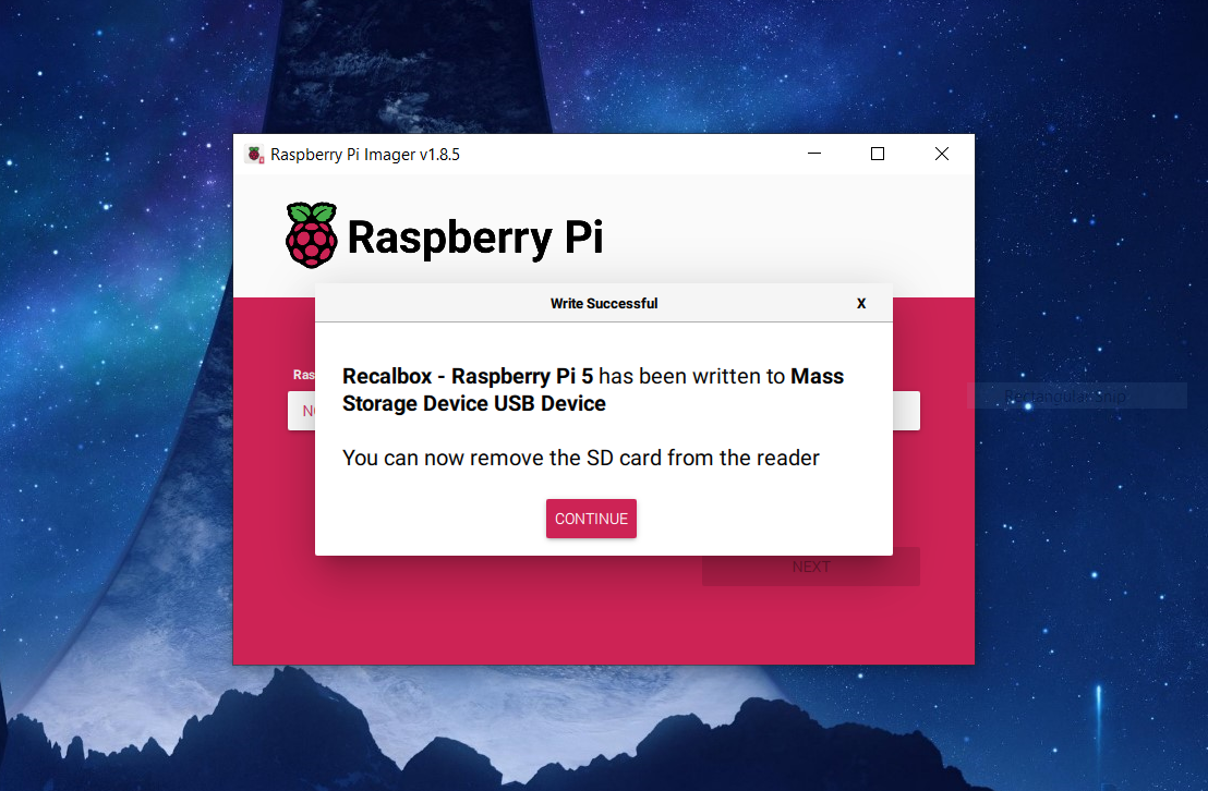
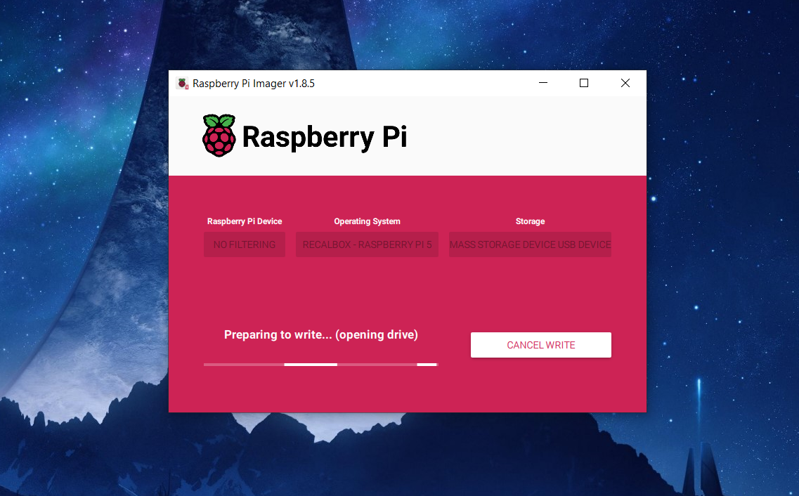
Recalbox is quite simple to install; all you need is a 32GB SD card and a Raspberry Pi imager. Then, all you have to do is choose the OS—Recalbox for Rpi5—and install it on the SD card.
Rufus and a Recalbox ISO file may be used to accomplish the same task, but a Raspberry Pi imager is more efficient and quicker.
-
17Configure GPIO Buttons
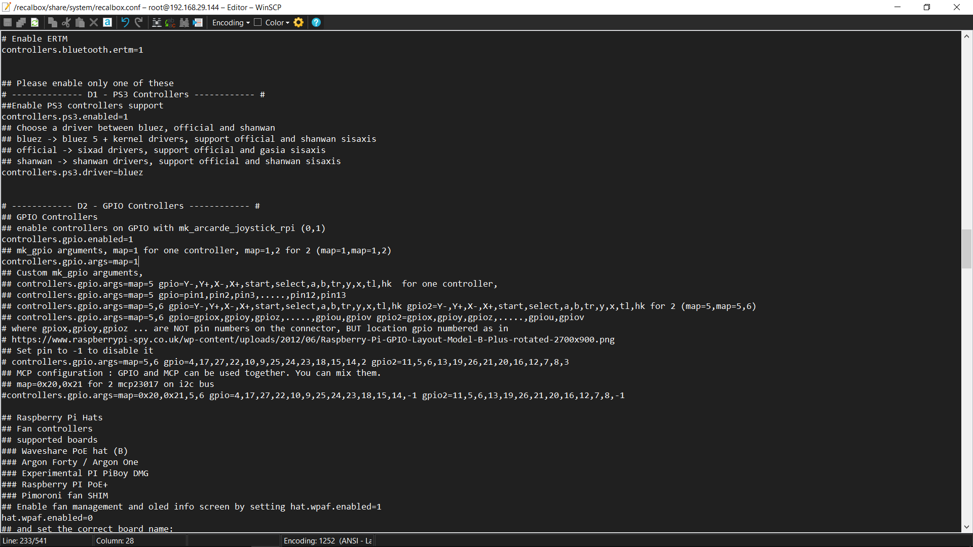
To enable GPIO buttons, we need to edit the Raspberry pi config file, which is located in this path. recalbox>share>system>recalbox.conf
- Because Recablox needs some time to load up, we must first boot the device before connecting to the Raspberry Pi. This will take a few minutes.
- We choose Network Settings from the Settings menu after booting up. By choosing the router's SSID and entering a password, we activate WiFi and establish a connection to the local network using the network settings.
- We obtain Pi's IP address from the network settings.
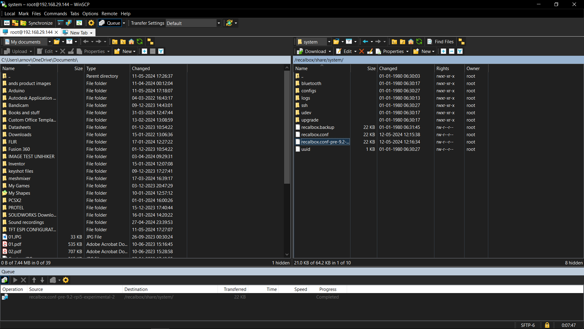
- Next, we open winSCH and establish a connection with the Pi by entering its IP address, password, and user name. These are recalboxroot and root, respectively.
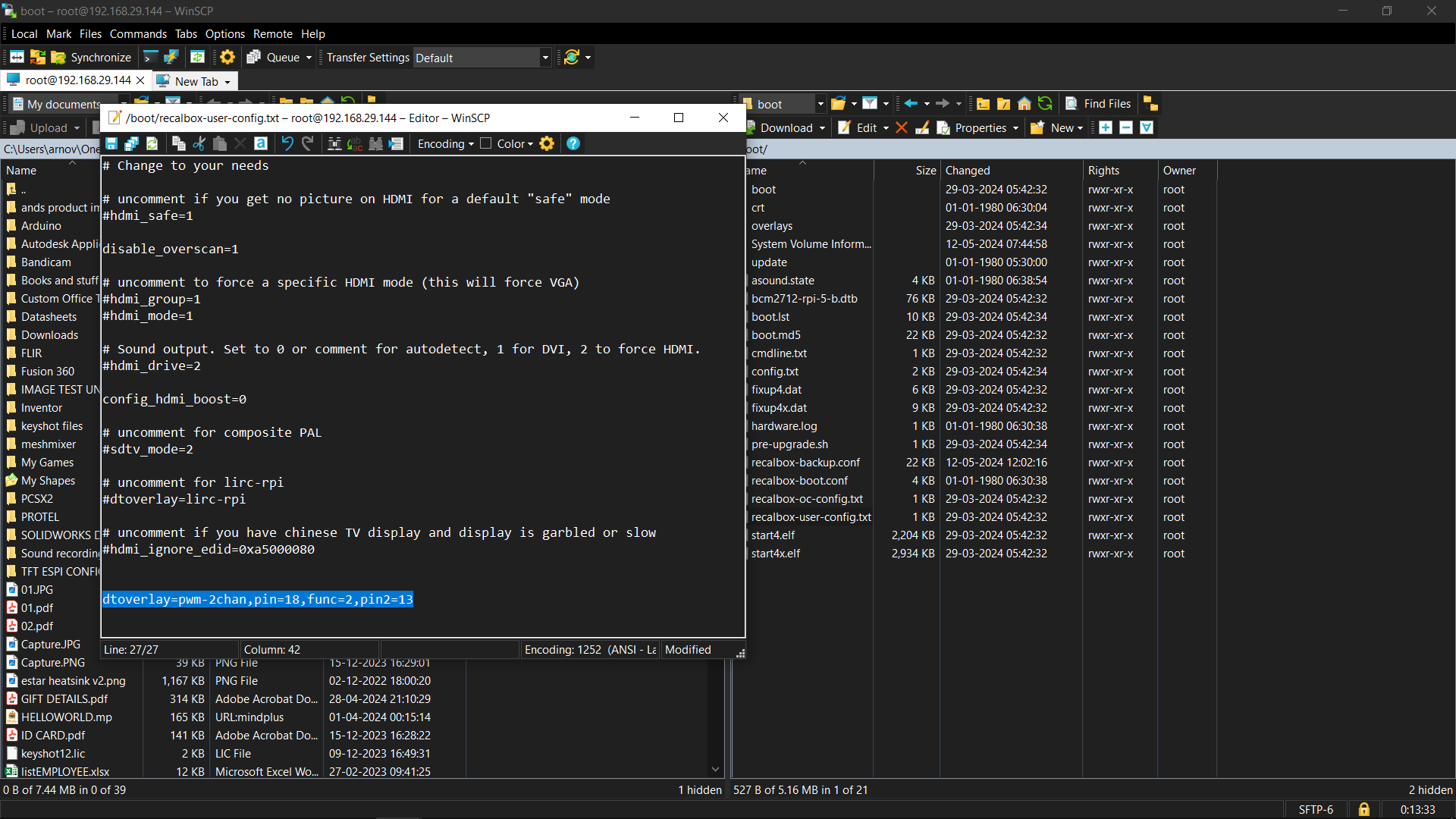
- We now go to the following path: recalbox>share>system>recalbox.conf and open the recalbox config file.
- We edited the below line, which will enable the GPIO buttons.
set controller.gpio.enabled = 1 (It was 0 before) and change controller.gpio.args.map=1, 2 to controller.gpio.args.map=1 (2 is second player controlls)
-
18Adding Games
![]()
![]()
![]()
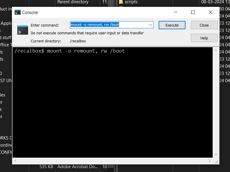
We must use the same procedure as before to enable the GPIO pins in order to add games to the Recalbox OS.
To add ROMs, you must first obtain the ROMs of the games you wish to play on this emulator. While it is not advised, most roms are obtained by piracy; however, since I enjoy being a pirate, you are free to obtain the rom file however you see fit.
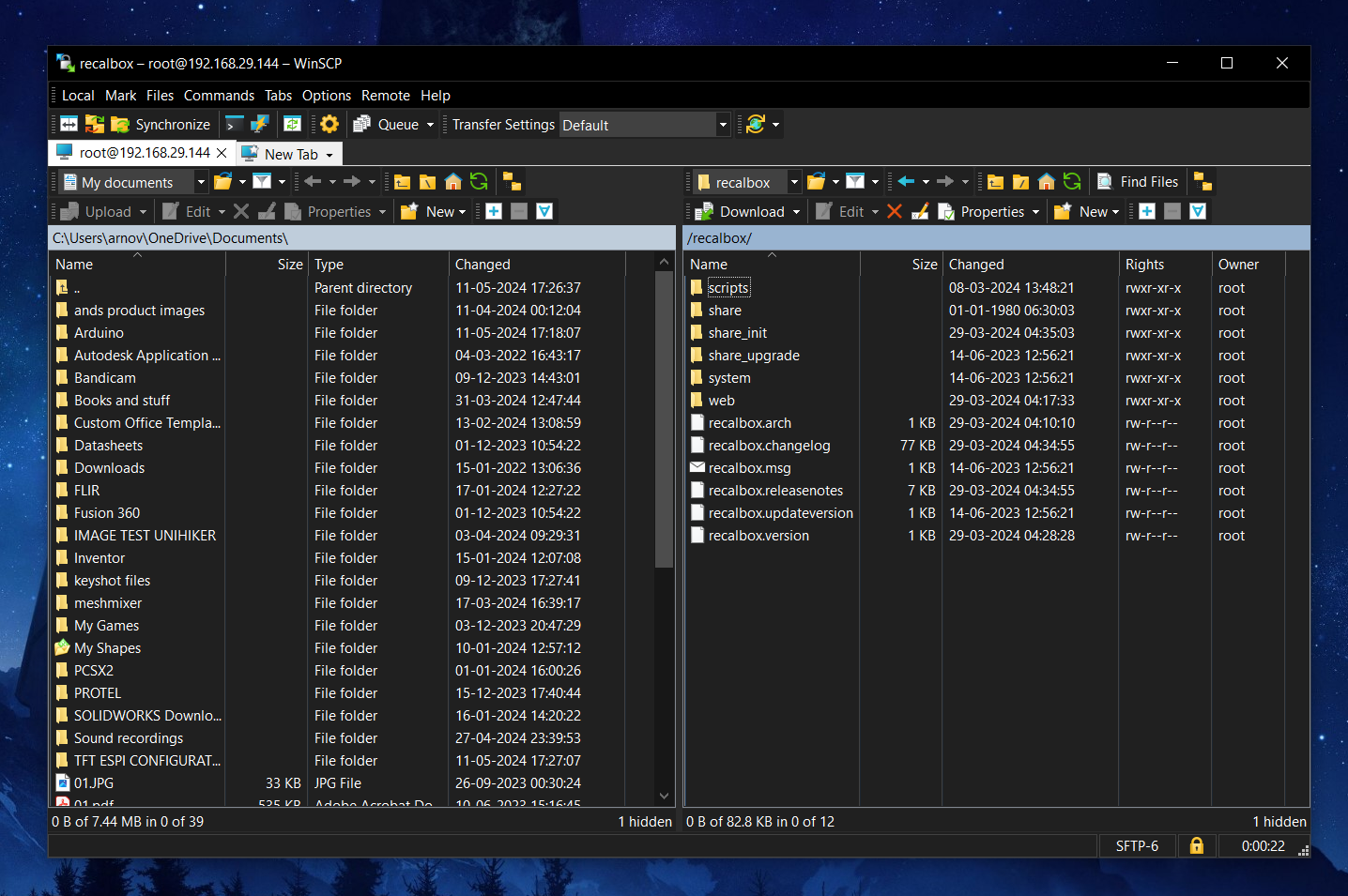
We use WinSCP again and get into the RecalBox OS by adding its IP address, username, and password.
Next, we go to this path, which contains all the ROM folders.
recalbox>share>rom
To play a game on the SNES emulator, for instance, we only need to add the game file to the SNES folder. Otherwise, we simply need to copy the unzipped game file or folder inside the ROM folders.
The procedure is quite easy to follow; all we have to do is download the game file, copy it into the ROM folder, and restart the computer for everything to work flawlessly.
-
19Result
![]()
![]()
![]()
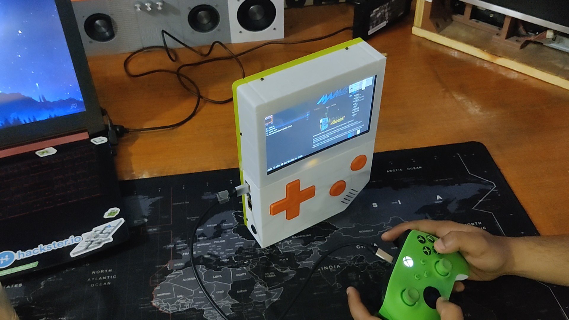
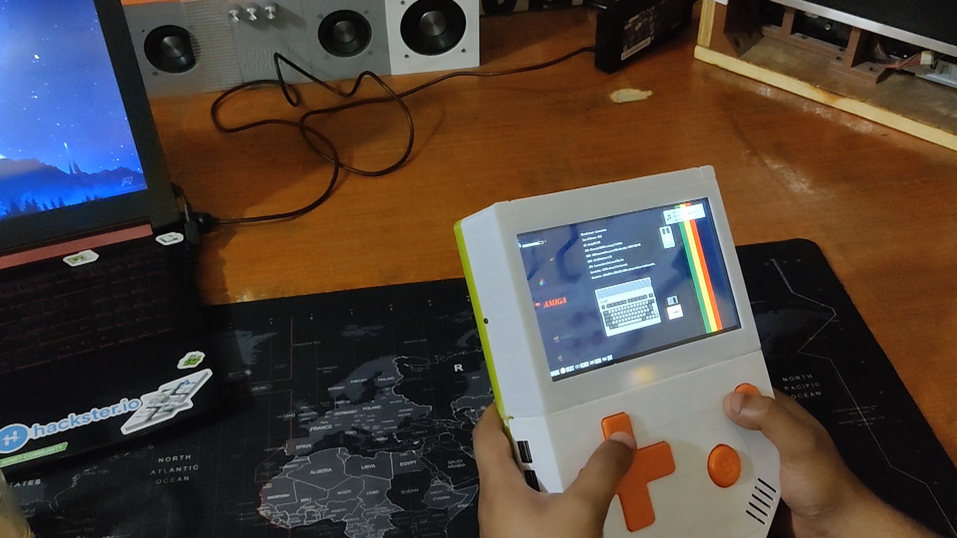
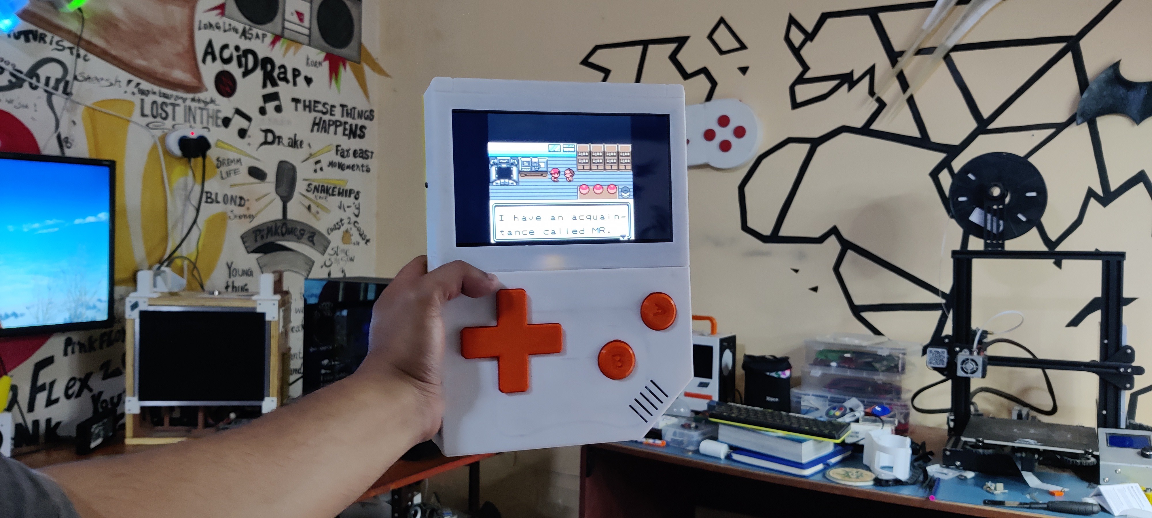
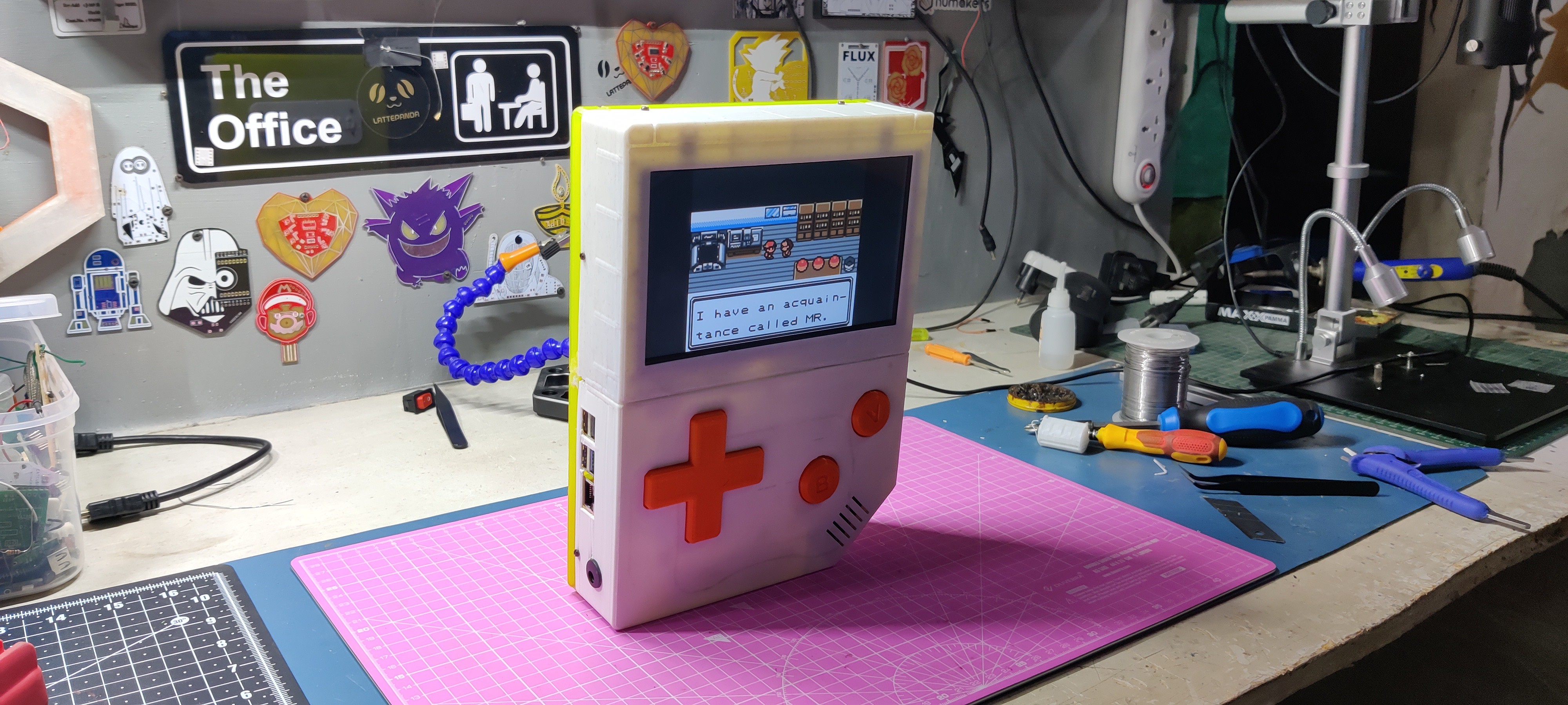
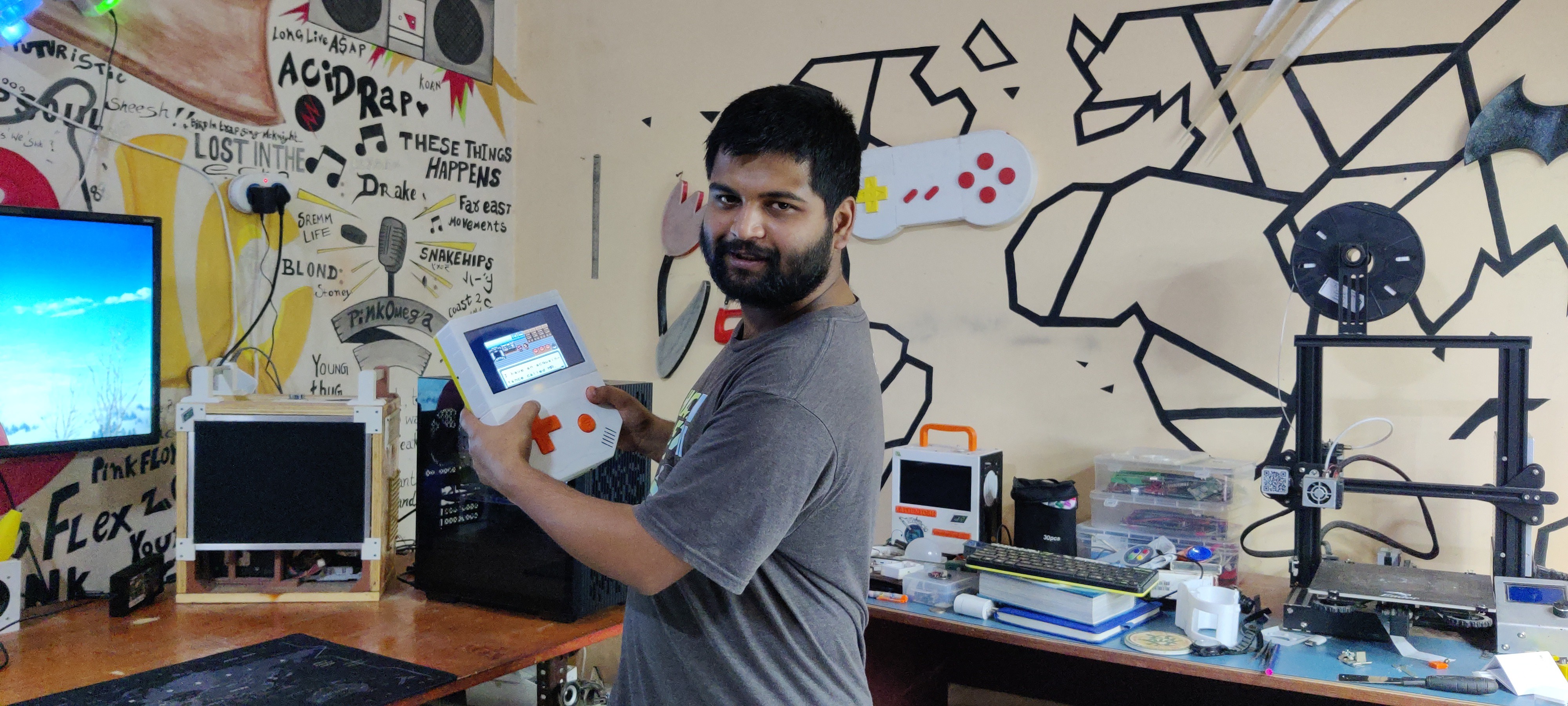
GameBox XL has been completed and here's how this project looks and works.
As you can see, this is no ordinary handheld console—it is thick and broad, slightly huge, and one hell of a chonky boy.
Thanks to the powerful Raspberry Pi 5, Recalbox is operating well (though not flawlessly; we will talk about that later). All of the games I played on this controller also worked without any problems.
For some reason, the BT Controller was not functioning correctly; it would connect for a short while before disconnecting. The USB controller functioned, so I connected my Xbox controller via a USB cable to play some classic titles, such as DOOM, Mortal Kombat, and Crash Bandicoo.
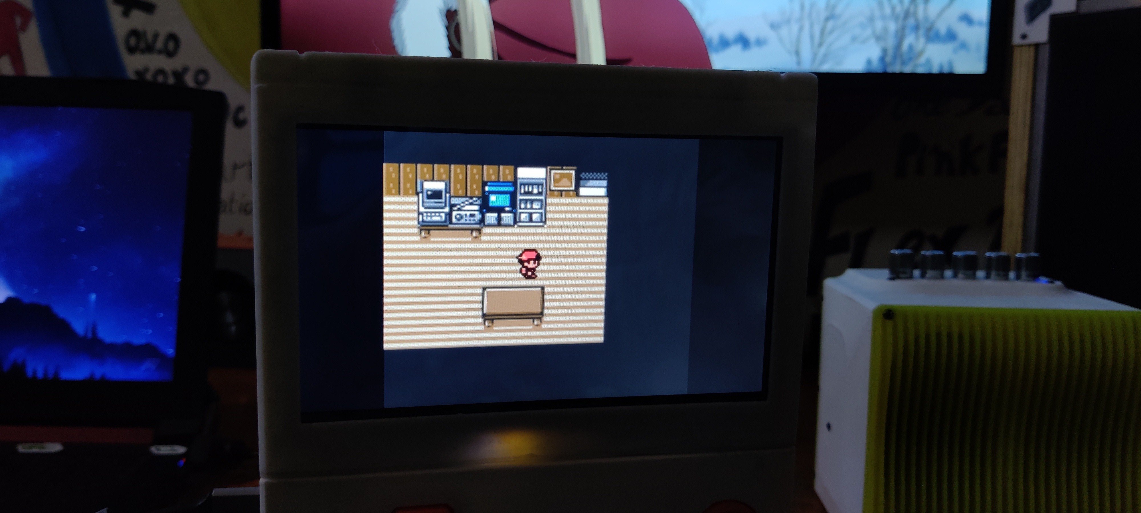
I even played a couple of older games, like the classic GBA Mario Kart and Pokemon Gold.
This gameboy ran everything I threw at it.
GPIO buttons were functional, but ultimately, there was a problem with the recalbox config file that kept overwriting my edits.
-
20Conclusion- What's next!
This project was successful overall; however, there were a few issues that needed to be fixed for the next iteration.
For example, the operating system that is presently running has a problem with the Raspberry Pi 5, which results in the jittering of the screen when choosing the emulator. Perhaps Reclabox will release a new build for the Pi5, or someone is already working on it; either way, this needs to be fixed.
Since the model's center of gravity is causing the stand to fail, the lid part needs to be redesigned. We also need to adjust the device's tilt angle.
Buttons function normally; however, occasionally GPIO buttons stop working. This appears to be a software problem, which I want to fix in the upcoming version.
Furthermore, the screen is really bad. It is dull and cannot be adjusted for brightness, so we cannot play games like Crash Bandicoo or Silent Hill on it. Crash Bandicoo is not even that dark, but it does not look nice due to the low brightness of the screen.
We will see if we can replace this screen with a vibrant IPS panel.
The battery life is decent, but in order to know how much juice is left, we need a battery power level monitoring device, which will be included in the next version.
Finally, in order to make this setup faster and more efficient, we will be using an M.2 NVME in the upcoming build.
These were the only few things that needed correction.
Leave a comment if you need any help regarding this project. This is it for today, folks.
Thanks to Seeed Studio for supporting this project.
You guys can check them out if you need great PCB and stencil service for less cost and great quality.
And I'll be back with a new project pretty soon!
 Arnov Sharma
Discussions
Become a Hackaday.io Member
Create an account to leave a comment. Already have an account? Log In.