-
1PCB Assembly Process
![]()
![]()
![]()
![]()
![]()
![]()
![]()
Three main PCBs must be assembled for this project in order to complete the PCB assembly process.
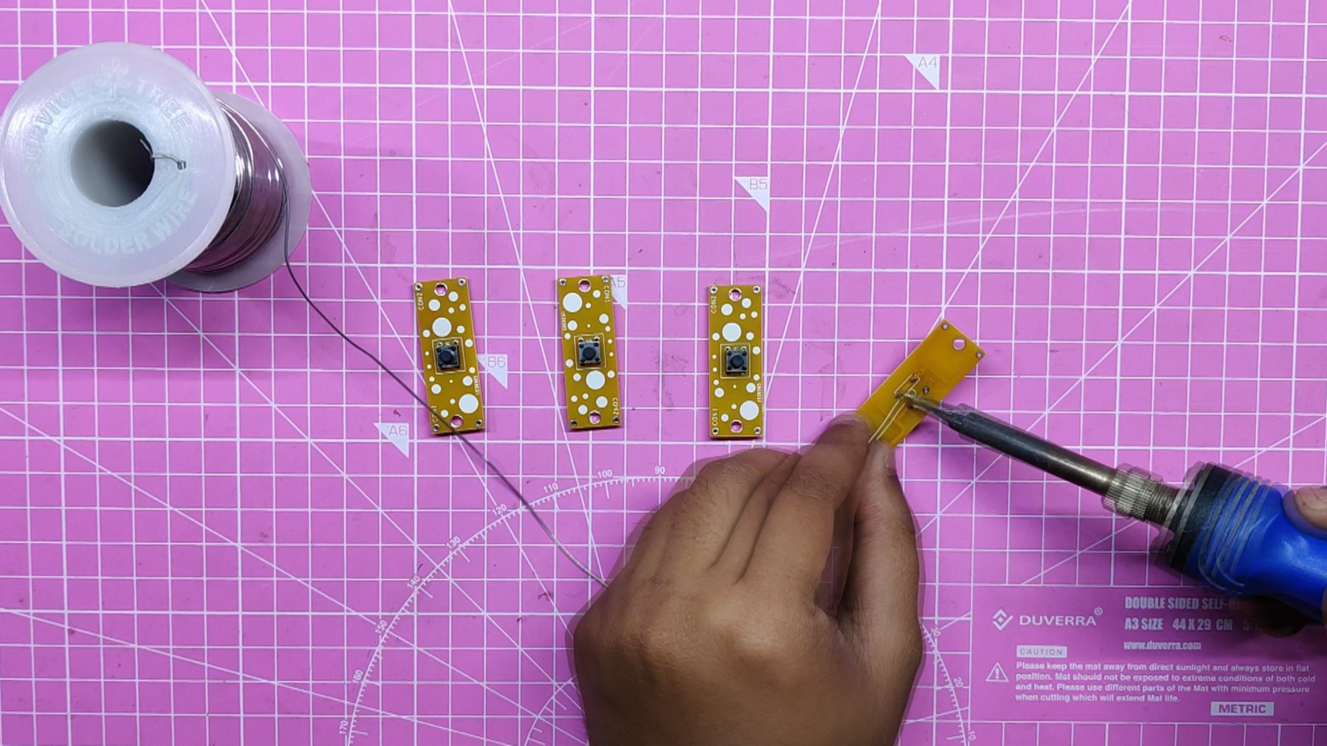
- The method of assembling the A-B Switch PCB begins with the installation of tactile switches to four Switch PCBs. (Even though we only need two PCBs, we make four.)
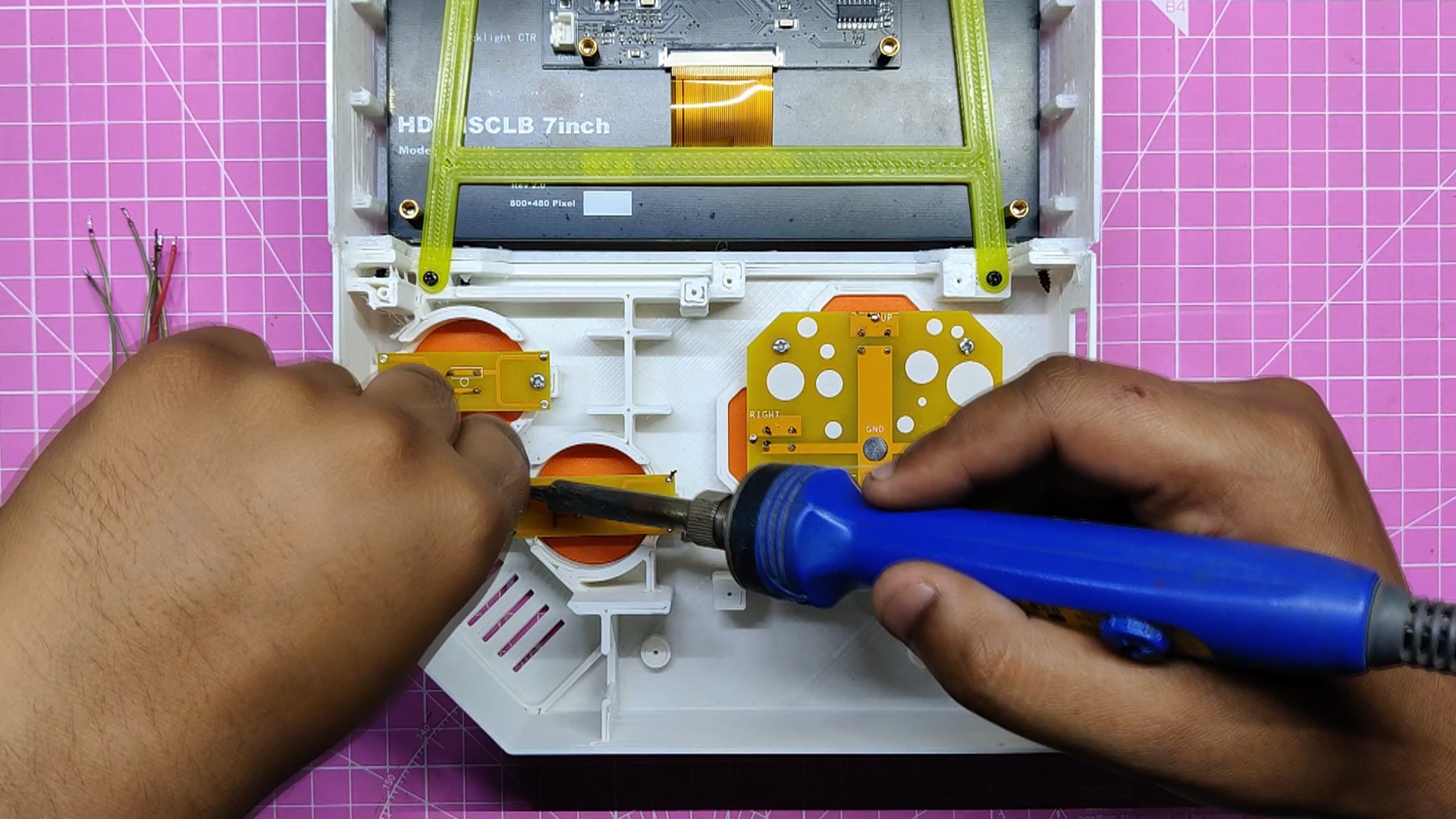
- The board is then turned over, and we use a soldering iron to solder the tactile switch pads.
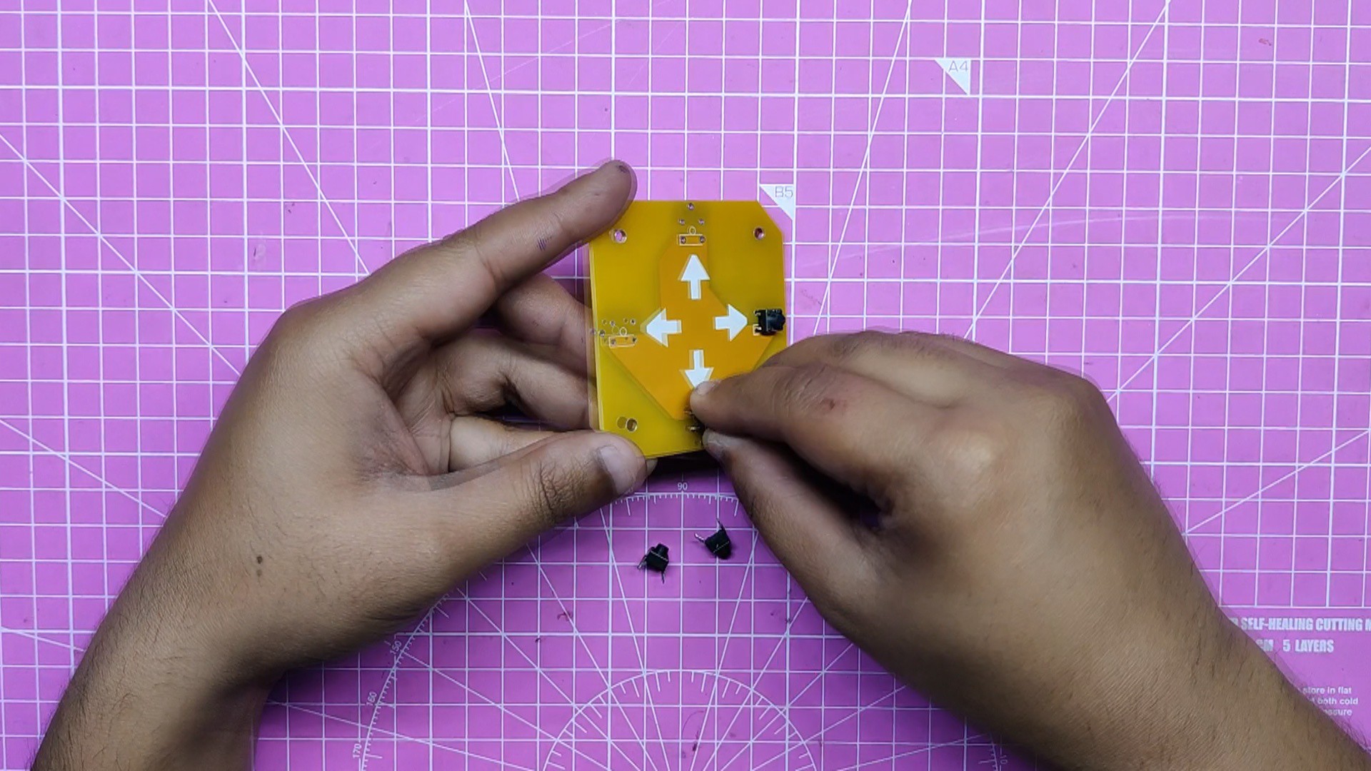
- For the DPad PCB, we repeat the same procedure, starting with the addition of four tactile switches to a single Dpad PCB.
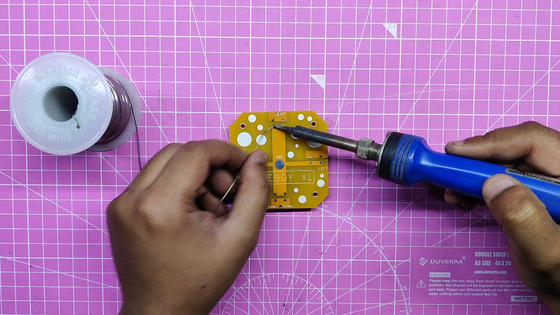
- We soldered the pads of the tactile switches using a soldering iron.
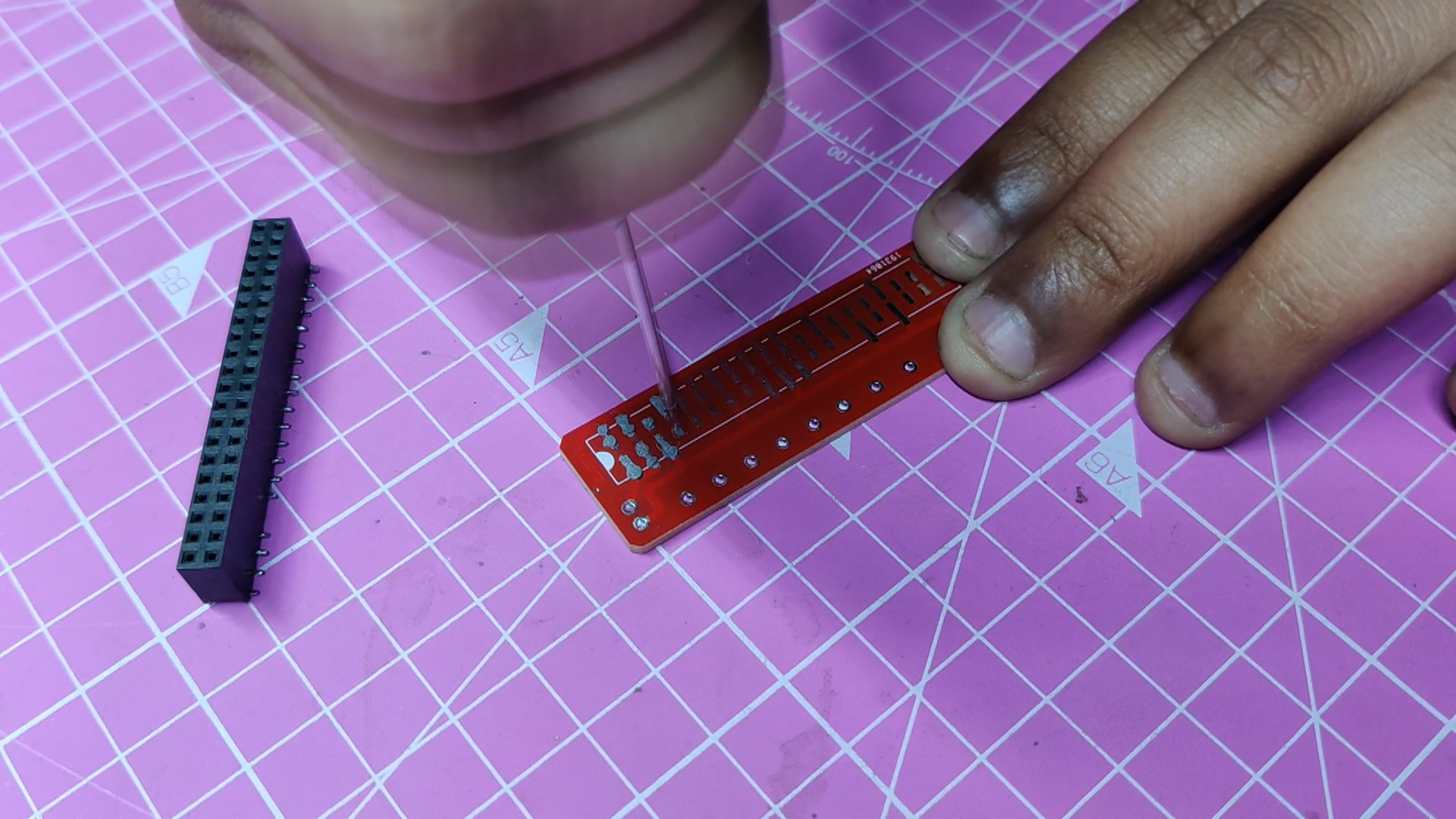
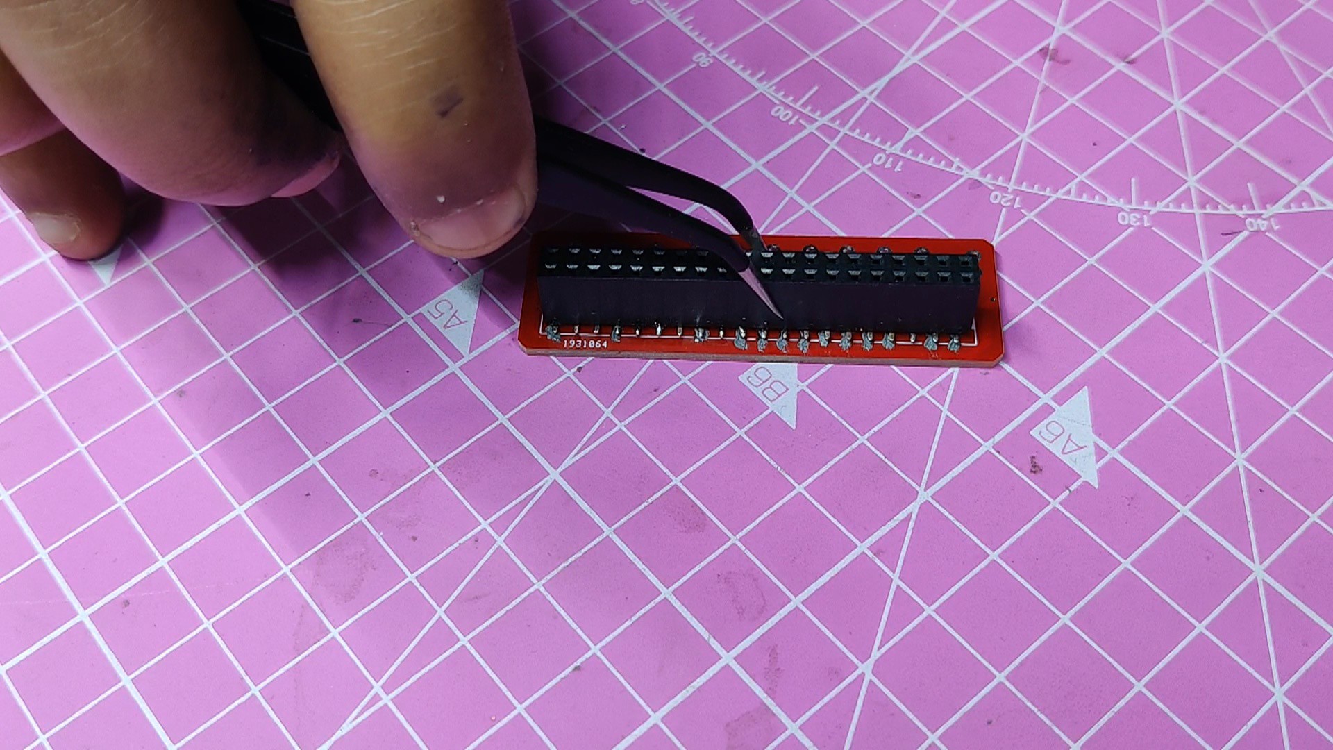
- Next, we are ready to assemble the GPIO breakout board by applying solder paste to the PCB pads.
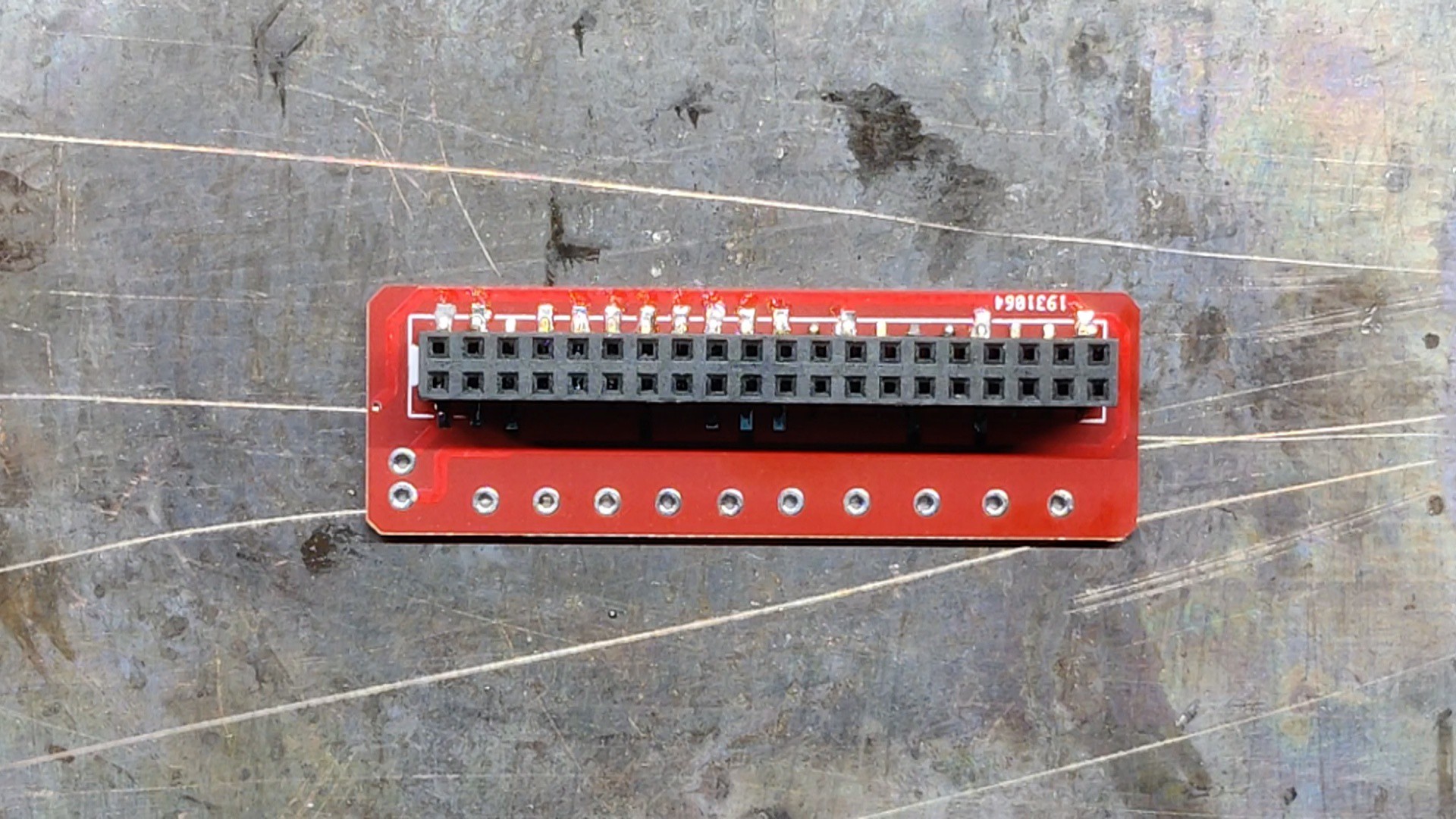
- Following that, we pick and position the SMD 40-pin GPIO connection on the GPIO breakout board.
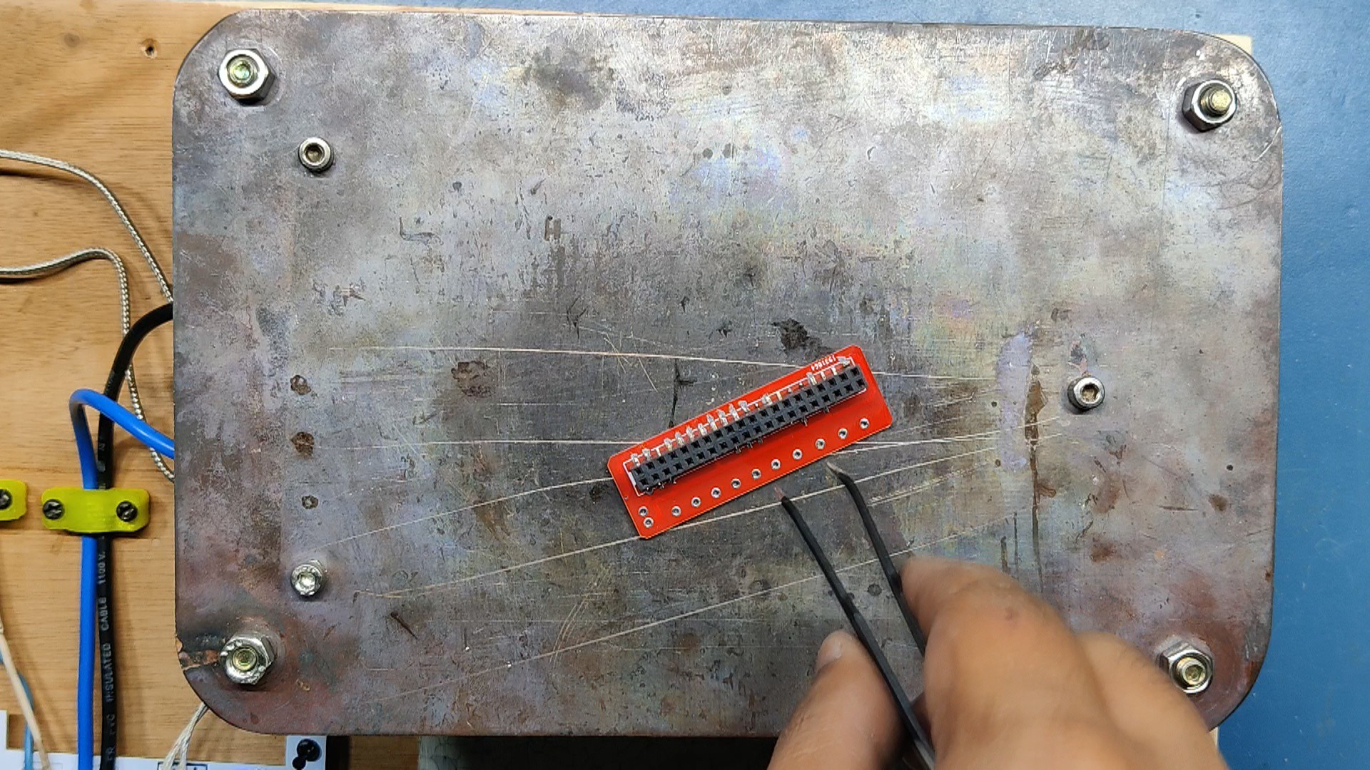
- The PCB was then raised and put on the SMD Reflow hotplate, which heated it from below to the temperature at which solder paste melts and the GPIO connector is connected to its pads. This process took place as soon as the temperature reached 200 degrees Celsius.
-
2Main Body Assembly
![]()
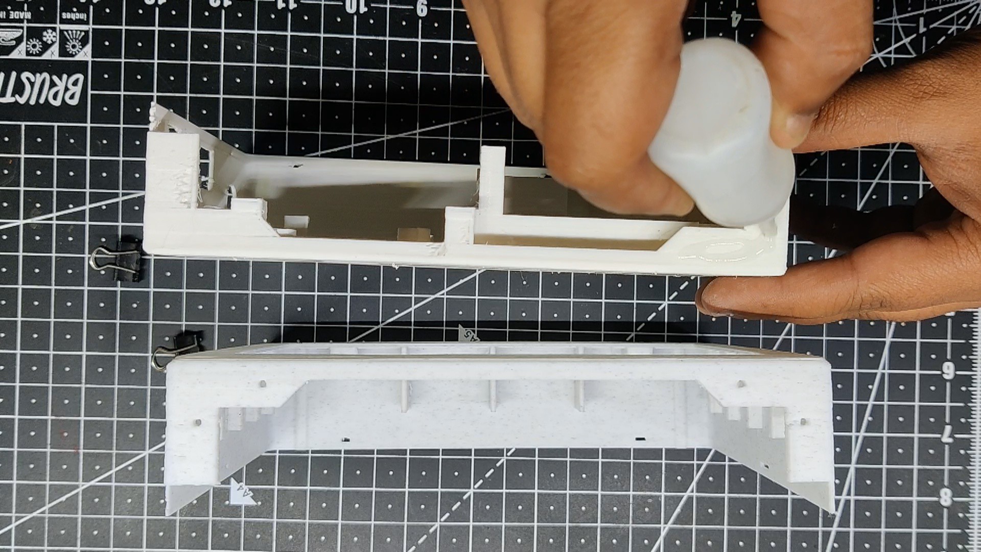
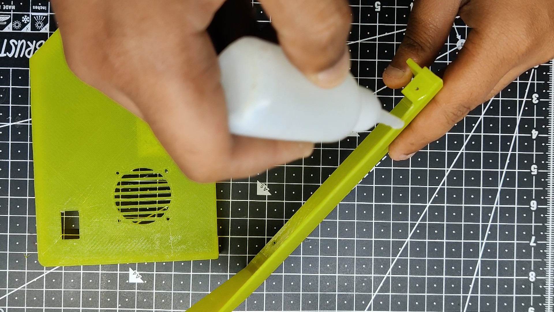
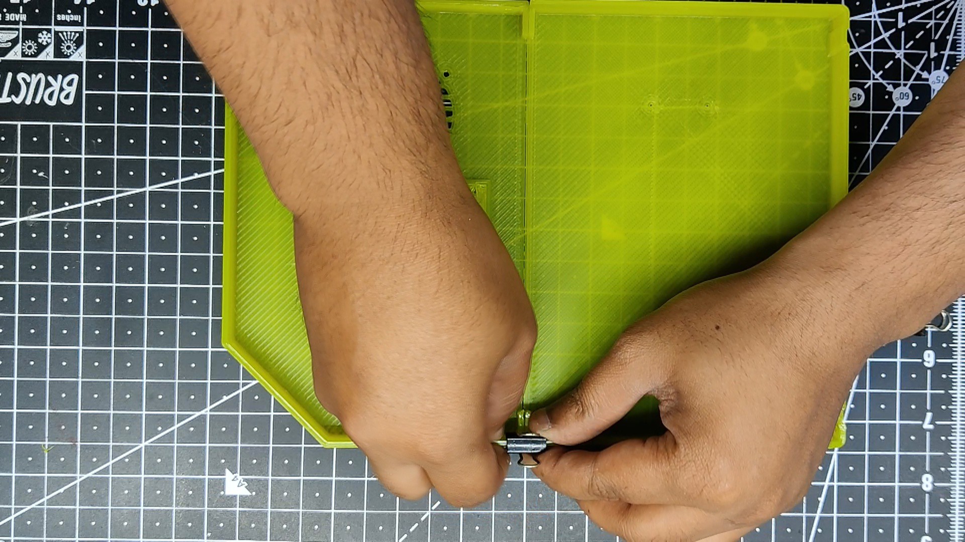
We begin the assembly procedure by gluing the upper and lower parts of the base body together with super glue.
- Paper clips are used to securely keep two items together once superglue has been applied to both of them.
- After an hour of curing the superglue, we took the paperclips out.
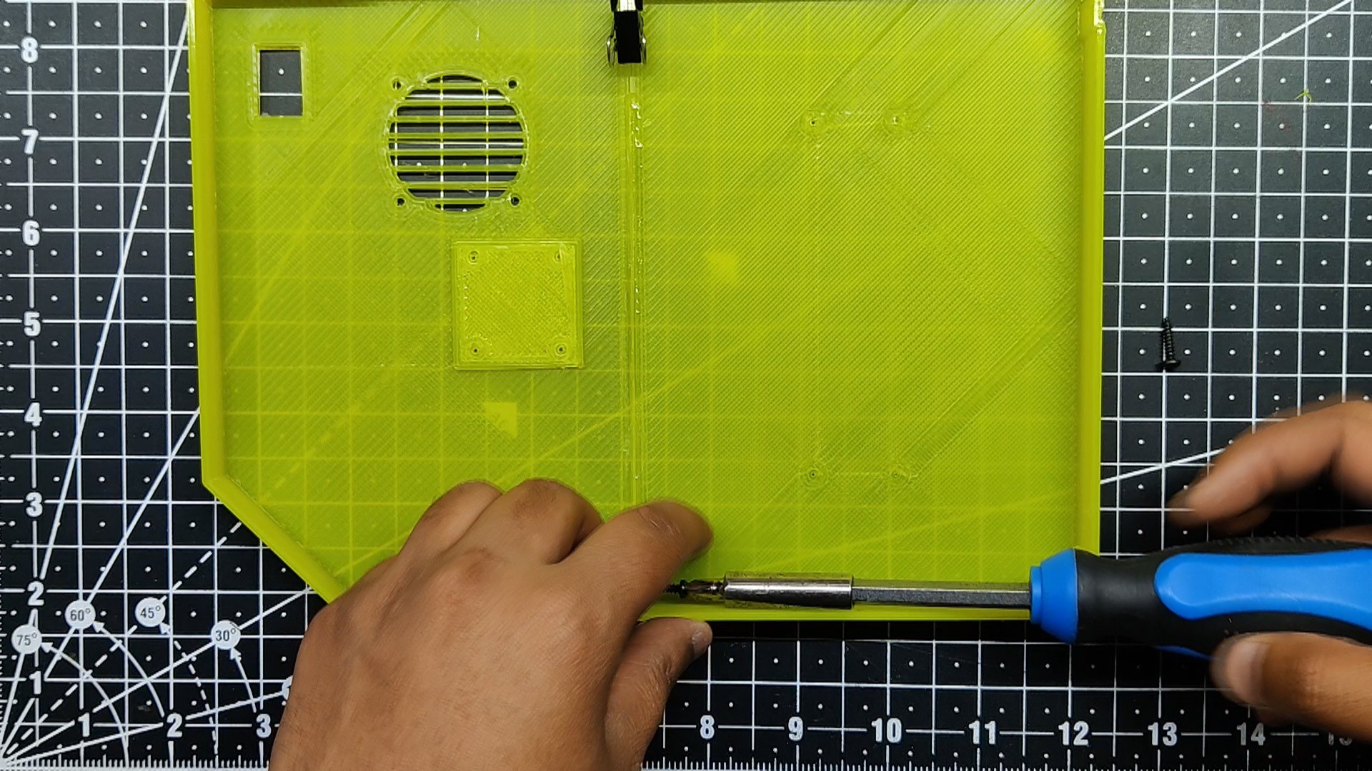
- Two M2 screws are used to fasten two sections together, which increases the joint's robustness and resilience. Holes were already created during the design phase.
-
3Lid Assembly
![]()
![]()
![]()
The next step involved assembling the lid, which was similar to assembling the base body. First, we had to combine both pieces together with super glue, allow it to set for an hour, and then use M2 screws to secure the two parts firmly so that the bond would be permanent.
-
4Complete Screen Assembly
![]()
![]()
![]()
![]()
![]()
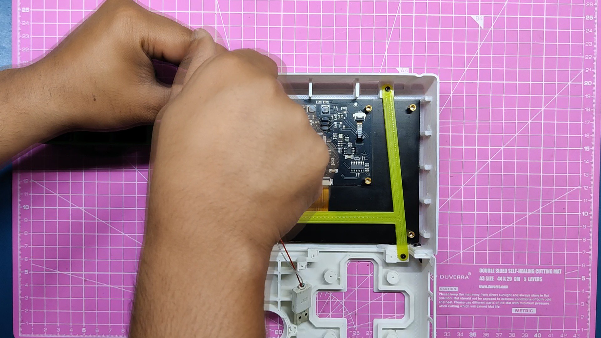
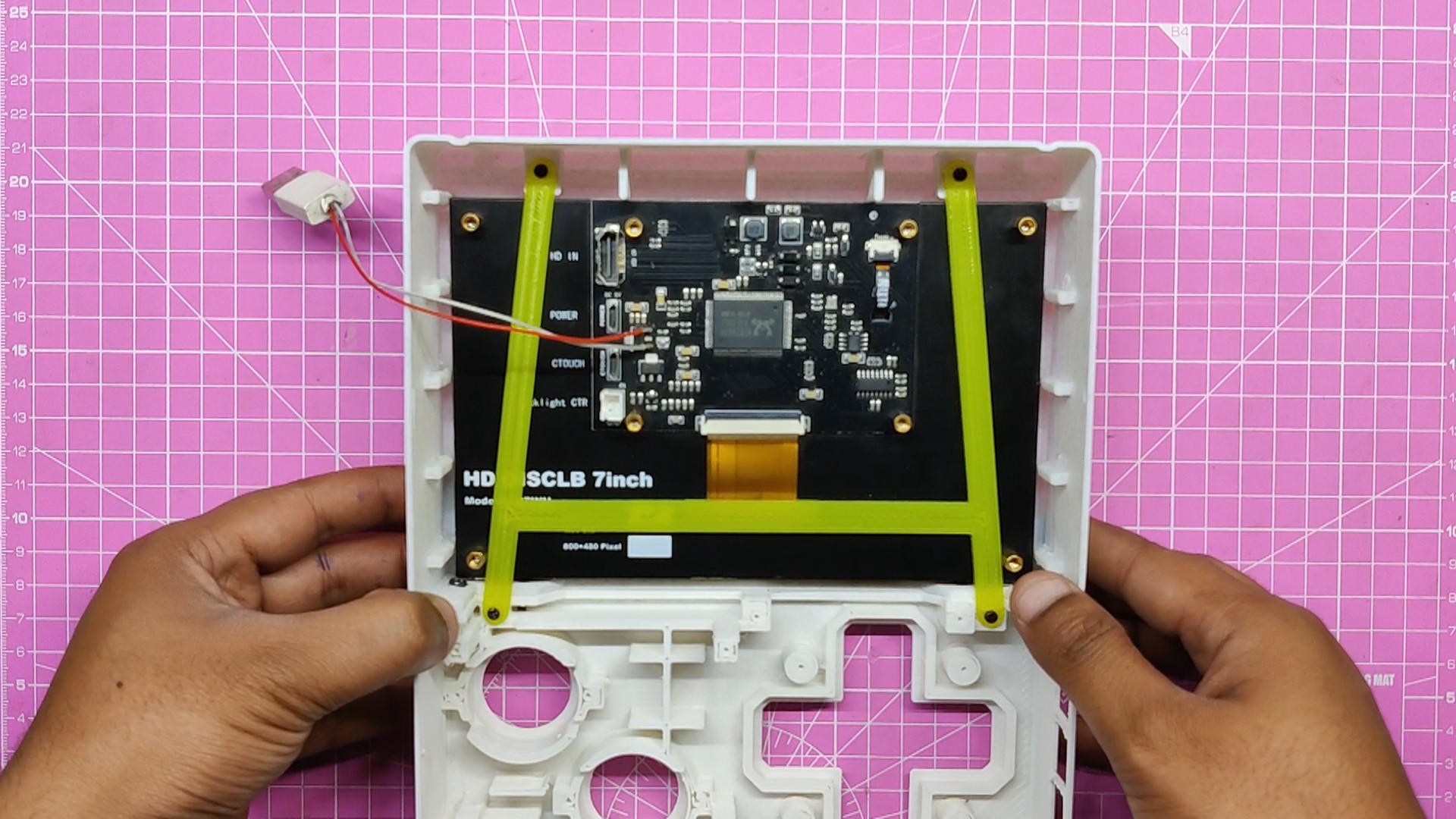
After preparing the body, we start the screen assembly process.
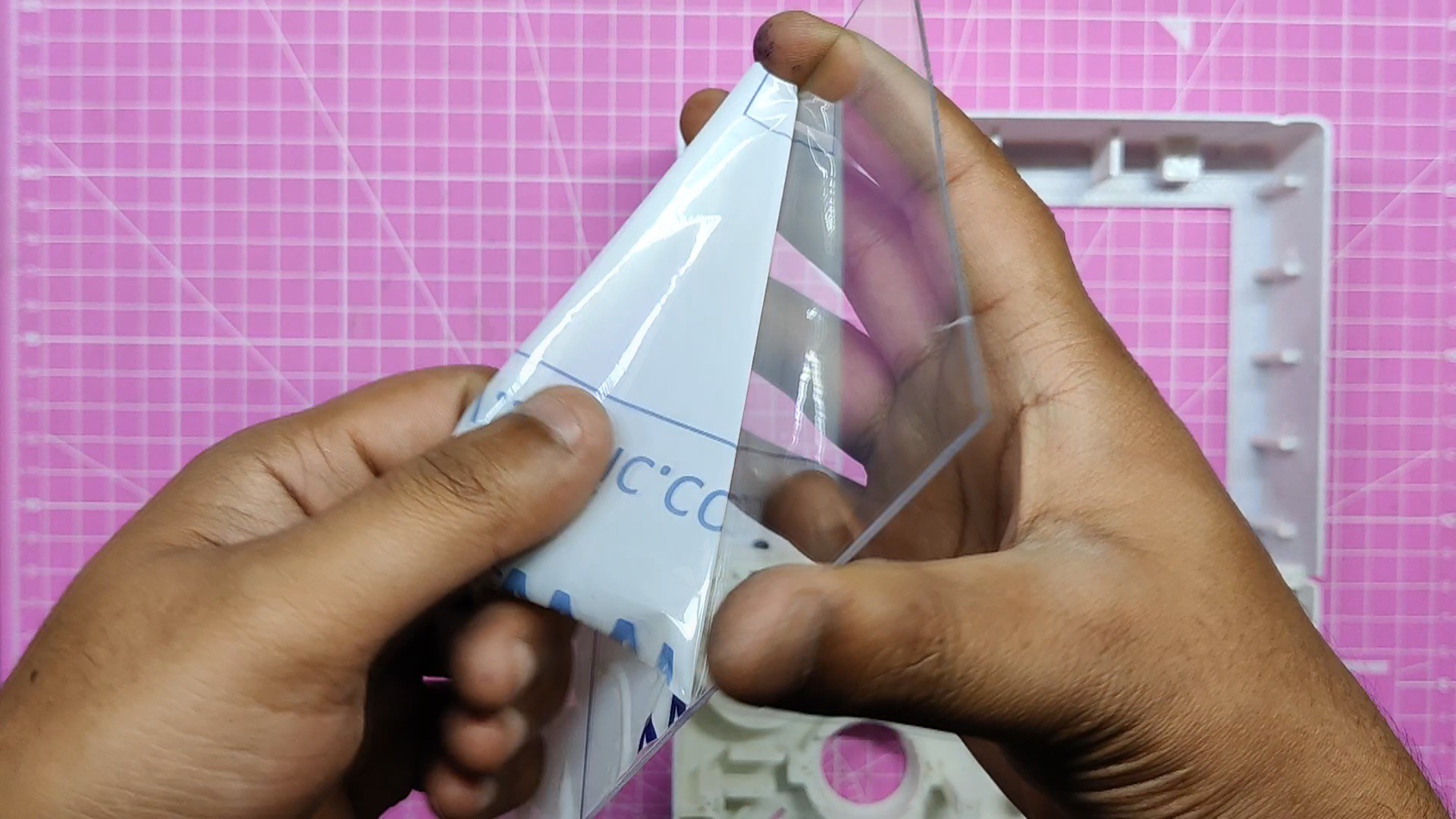
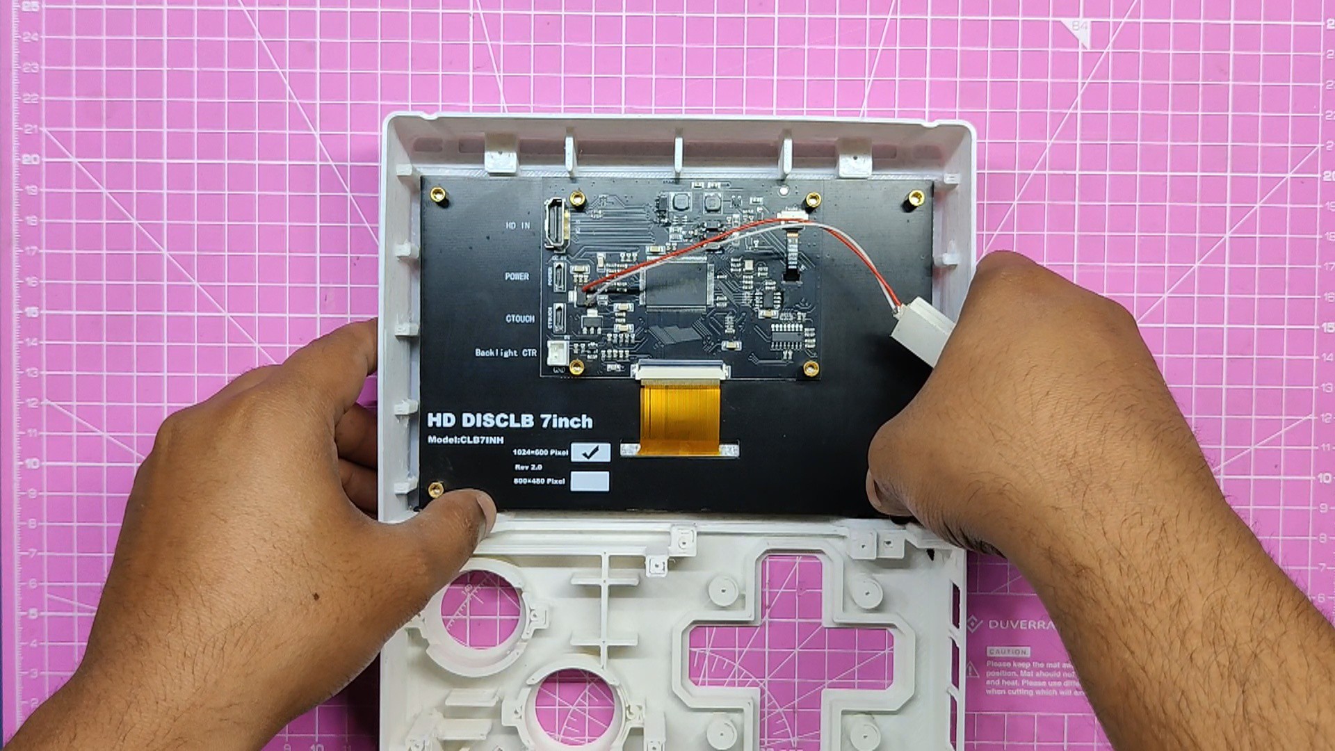
We are utilizing a 7-inch HDMI display here, and since the glass layer covering the front half of the panel is easily broken, we intend to place a 1mm-thick acrylic sheet between the display and the inside of the body to protect it from dust and damage.
We took a 163mm x 100mm piece of acrylic sheet and peeled its protective layer from both the front and back sides.
The acrylic sheet is then positioned as the screen, where it is secured in place by ribs that have been added all around it. These ribs will help eliminate screen wobbles and hold the screen firmly in place. Ribs have been utilized as a design technique in many screen- and battery-related products to help keep the component intact and minimize its movement inside the enclosure or casing.
We then slide the screen into its place.
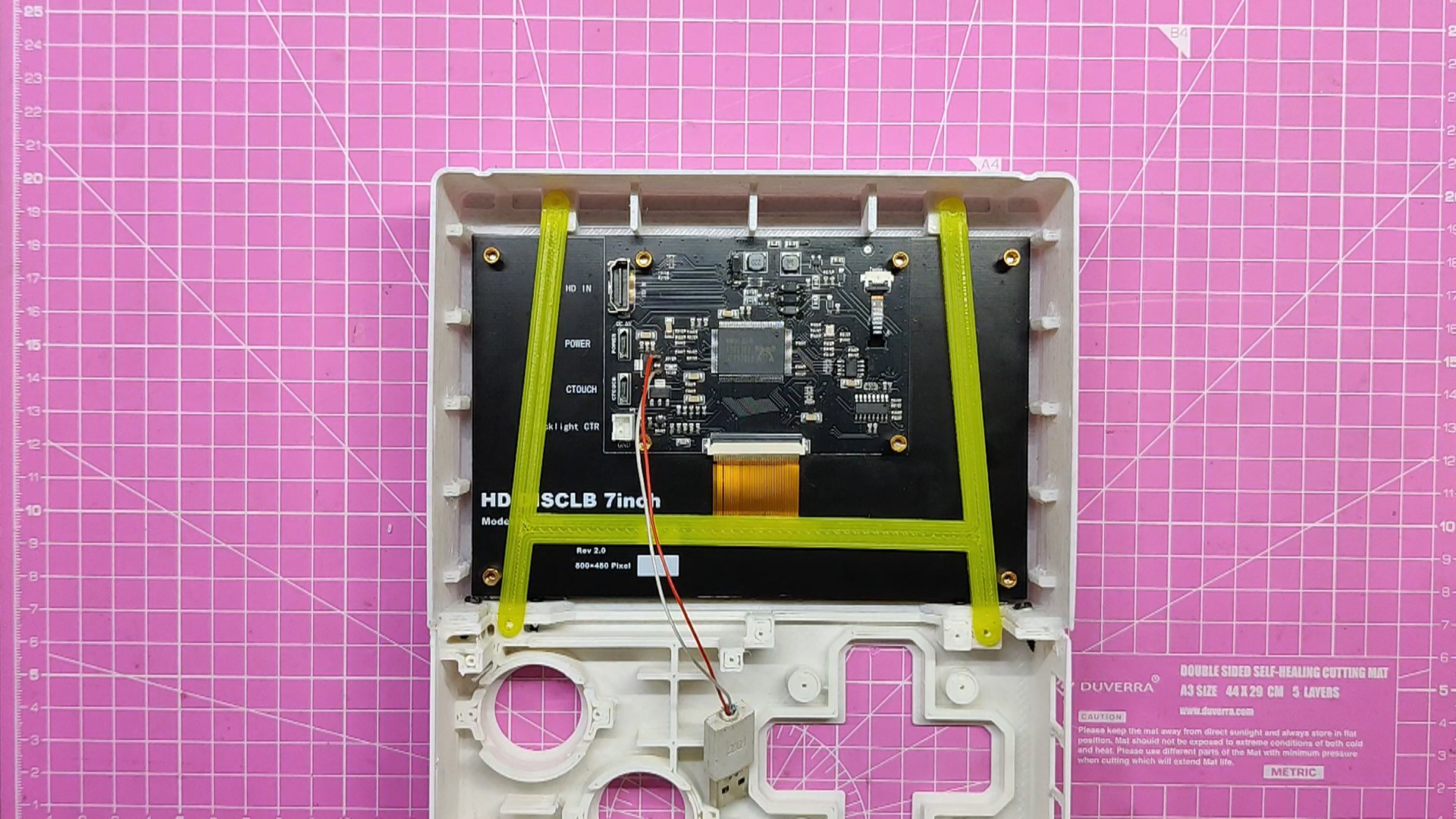
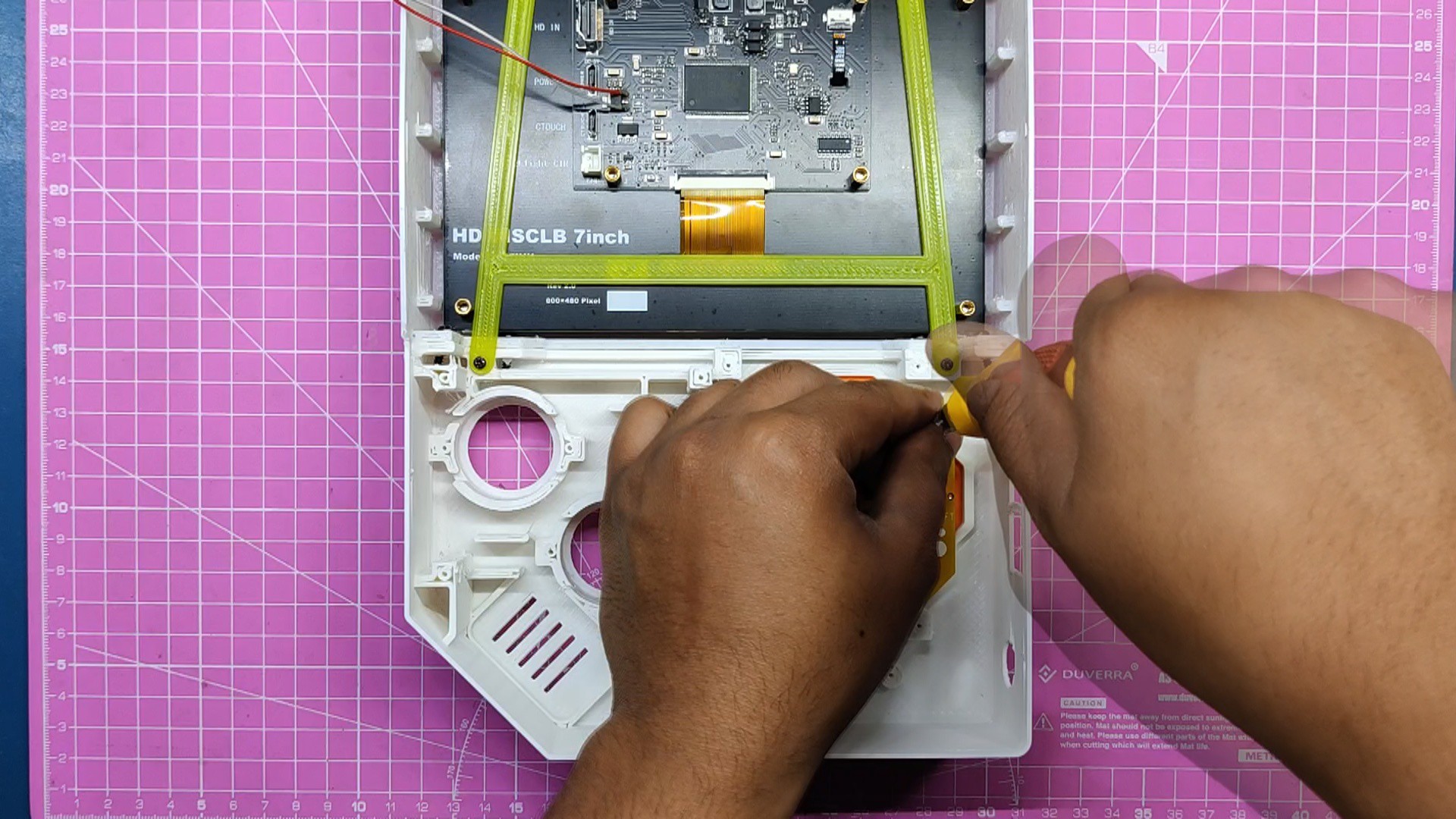
The screen holder is then used to hold the screen in place. It is positioned on the rear of the display and is secured to the bosses on the base body with M2 screws.
Screen assembly is complete; next, we add buttons.
-
5Complete Button Assembly
![]()
![]()
![]()
![]()
![]()
![]()
![]()
![]()
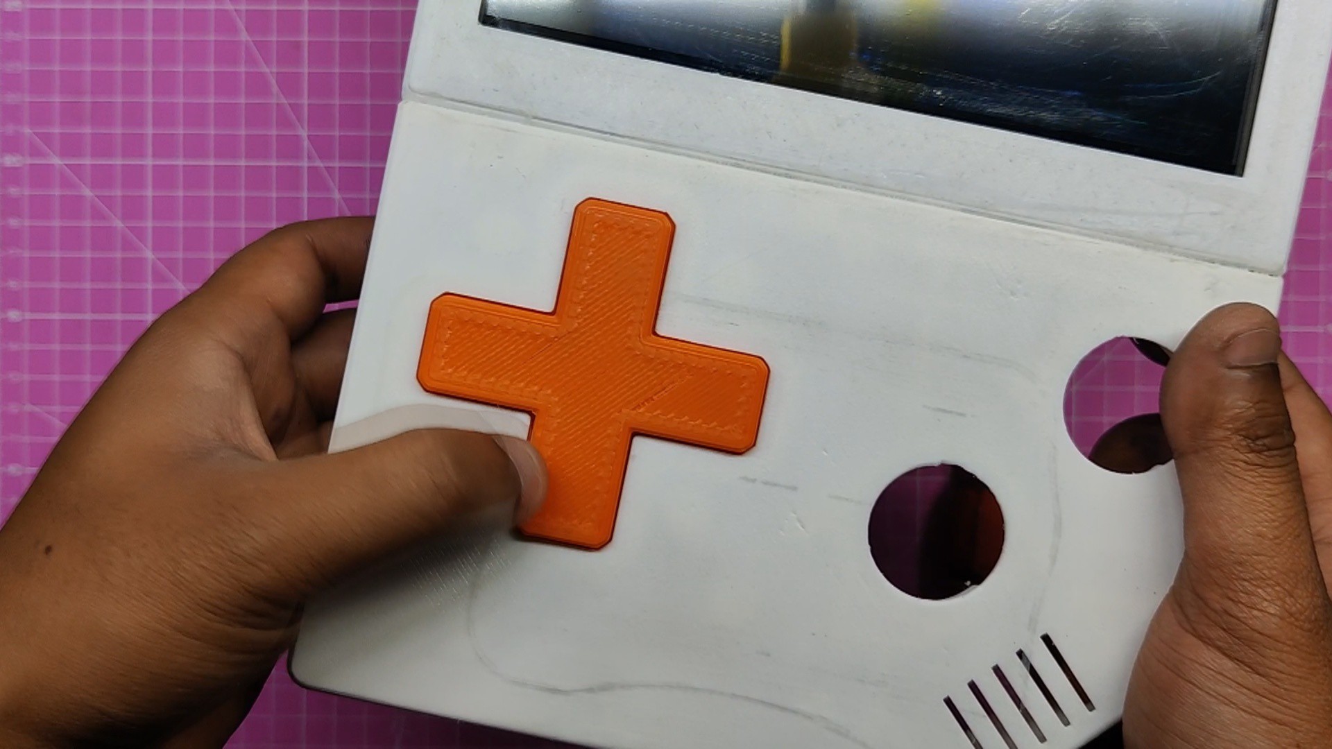
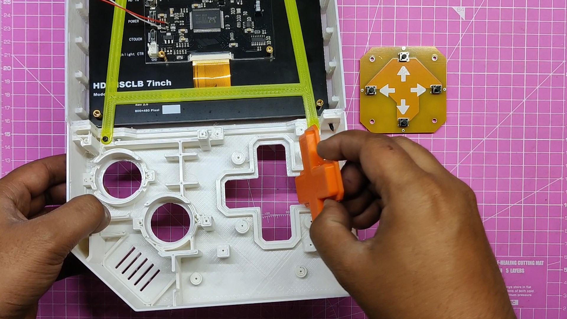
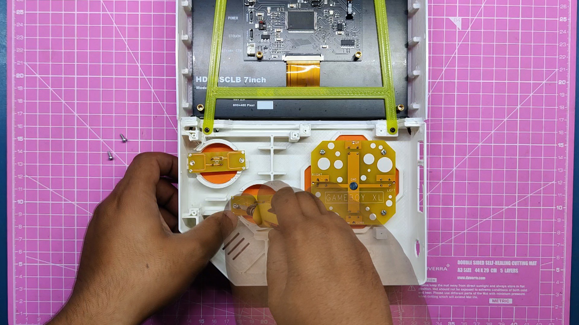
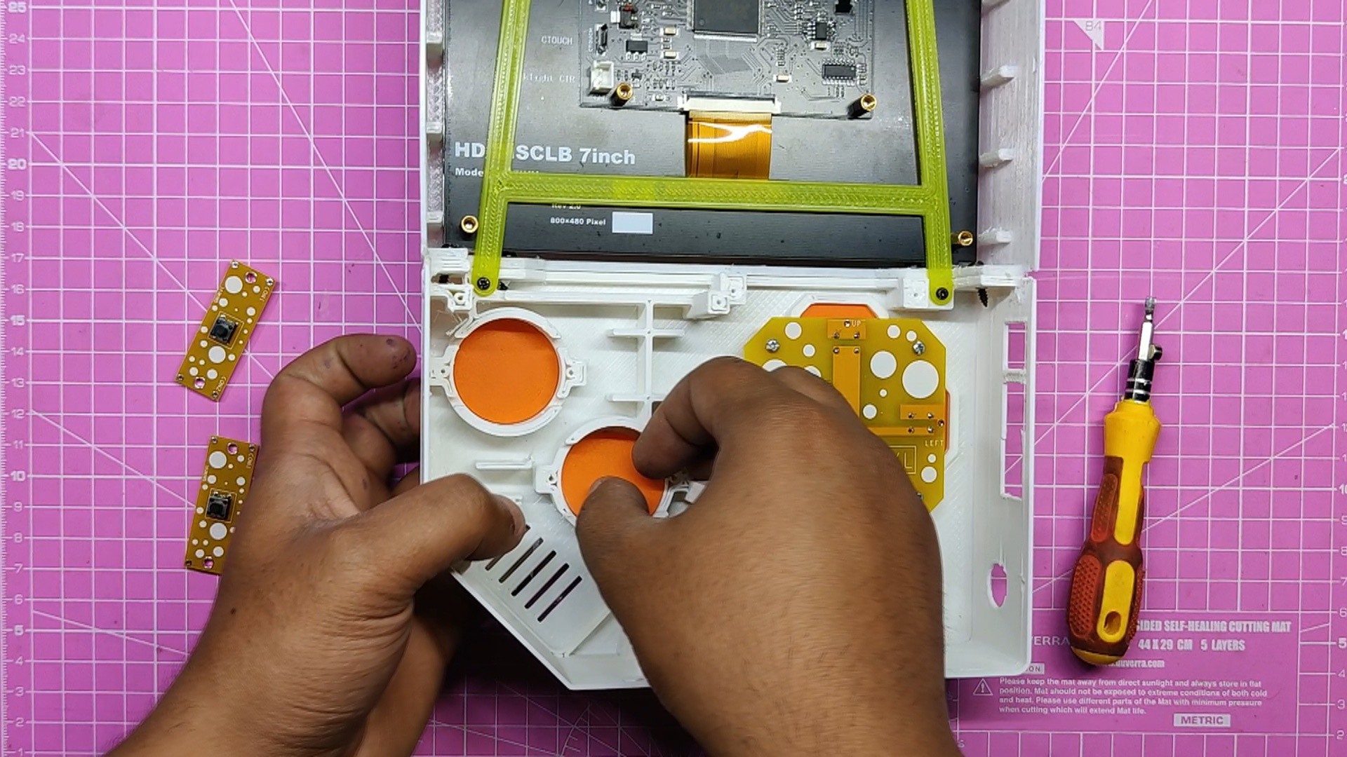
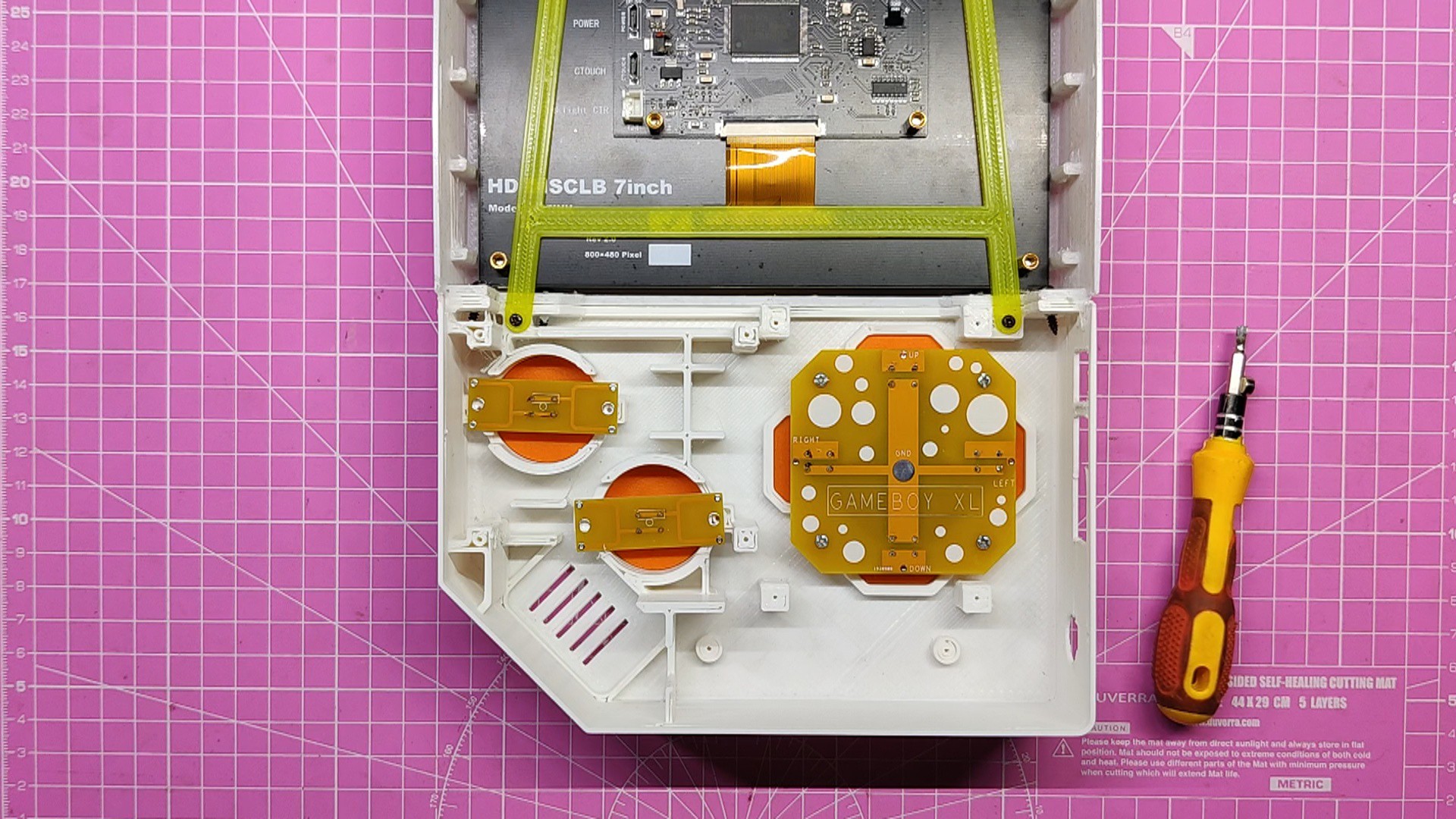
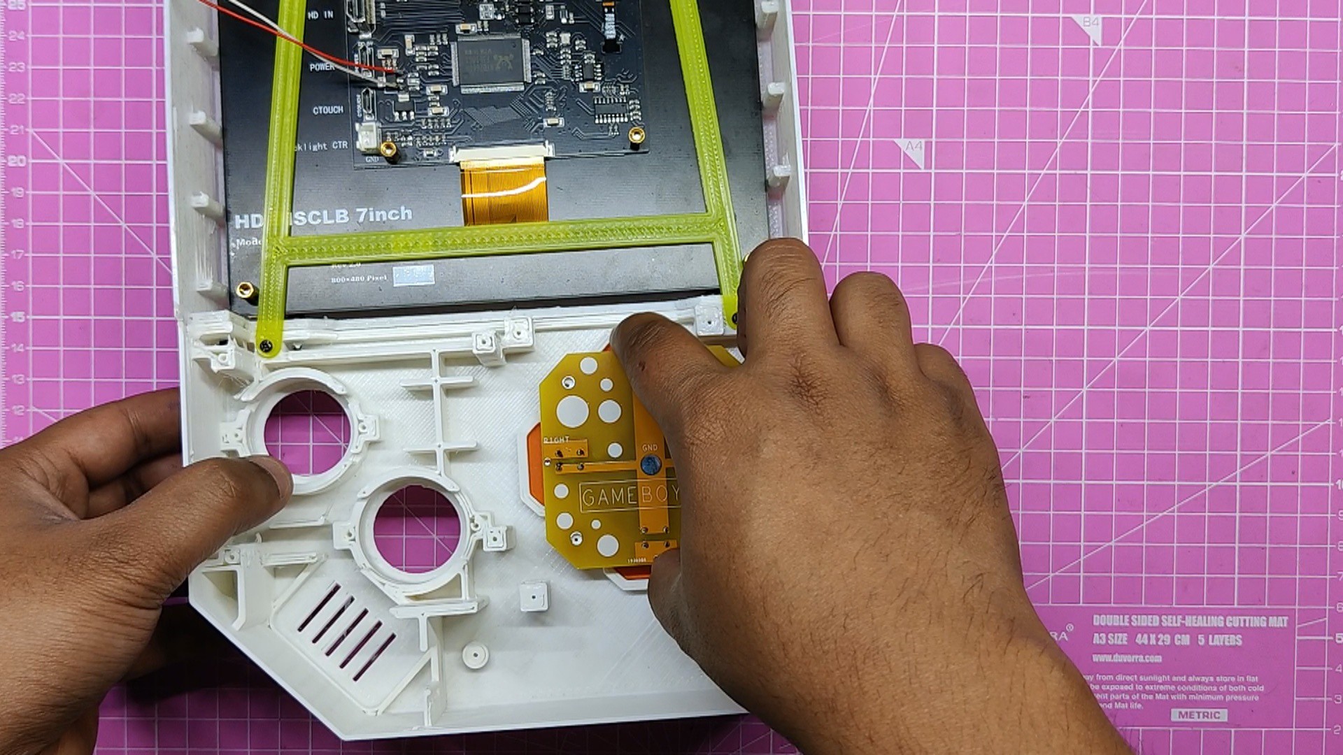
- The D Pad button was assembled simply by first positioning it on the base body and then placing the DPad switch on top of it.
- The PCB is mounted to the base body using M2 screws. It is important to provide a 1 mm gap between the switch knob and the 3D printed button, so that the button can travel freely in the intended position and toggle the tactile switch when pressed.
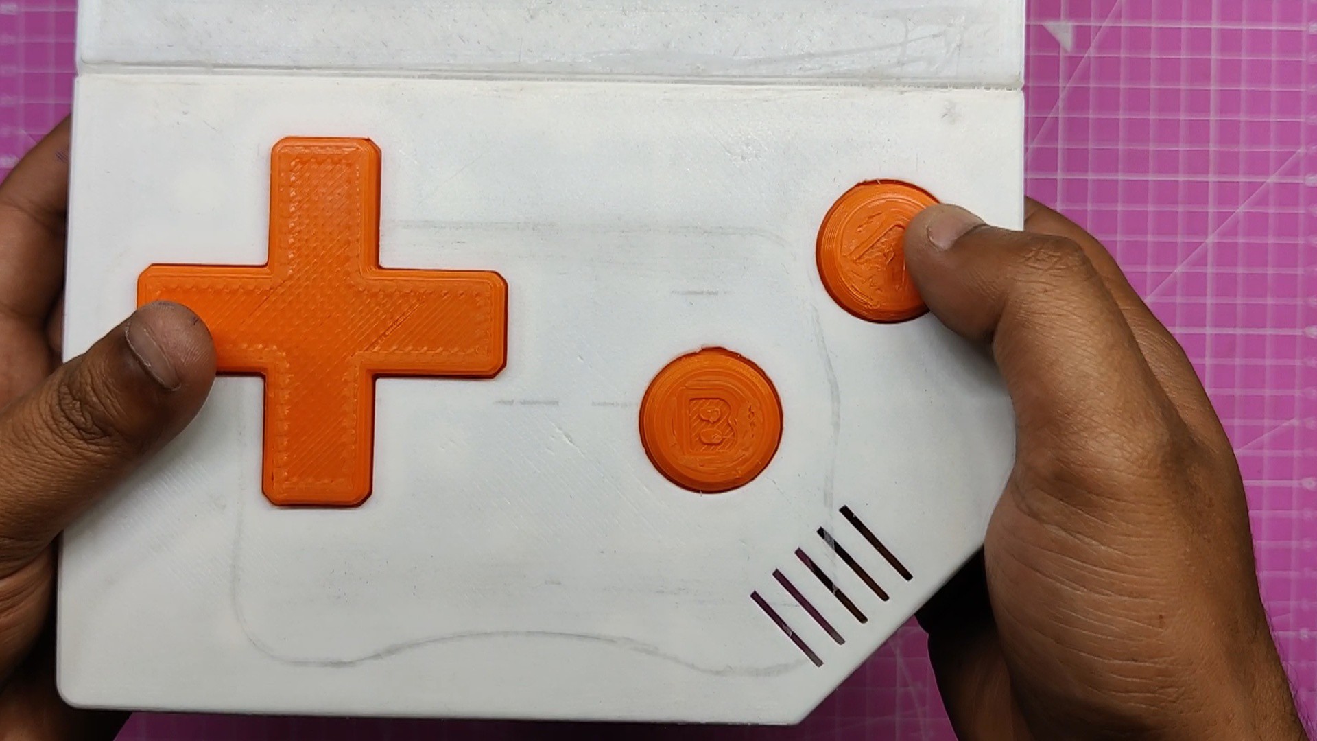
- After that, we inserted the A-B buttons in their proper locations and positioned the PCBs on top of the buttons. Finally, we used M2 screws to fasten the PCBs in place.
-
6Pi Holder Assembly
![]()
![]()
![]()
![]()
![]()
![]()
![]()
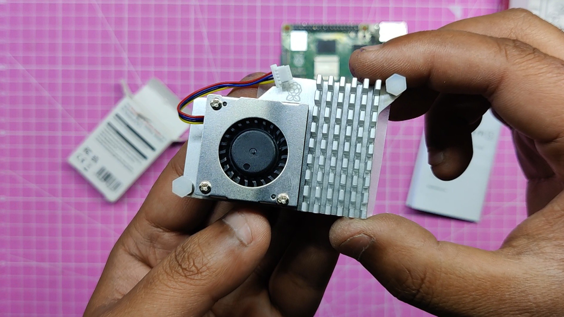
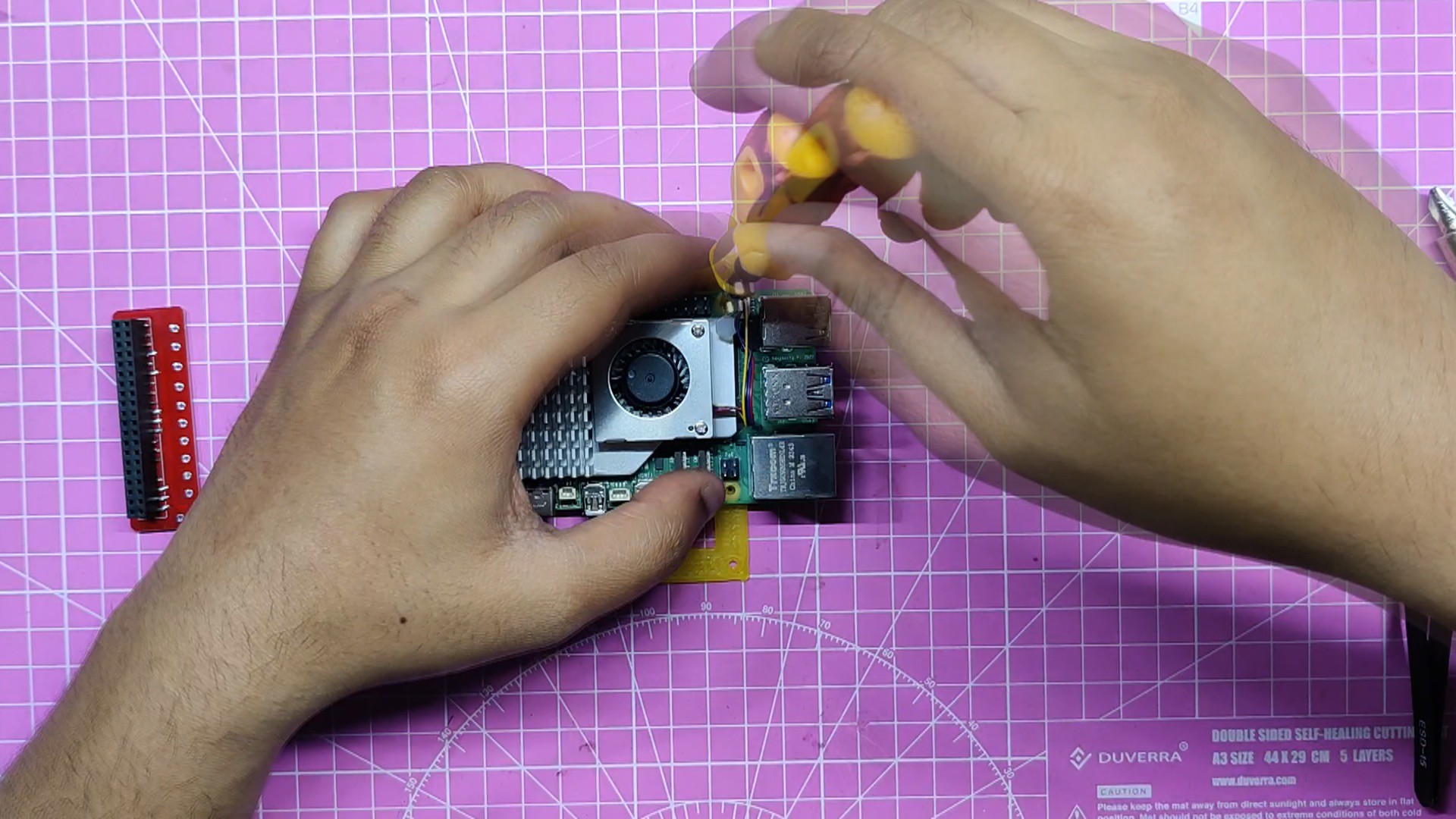
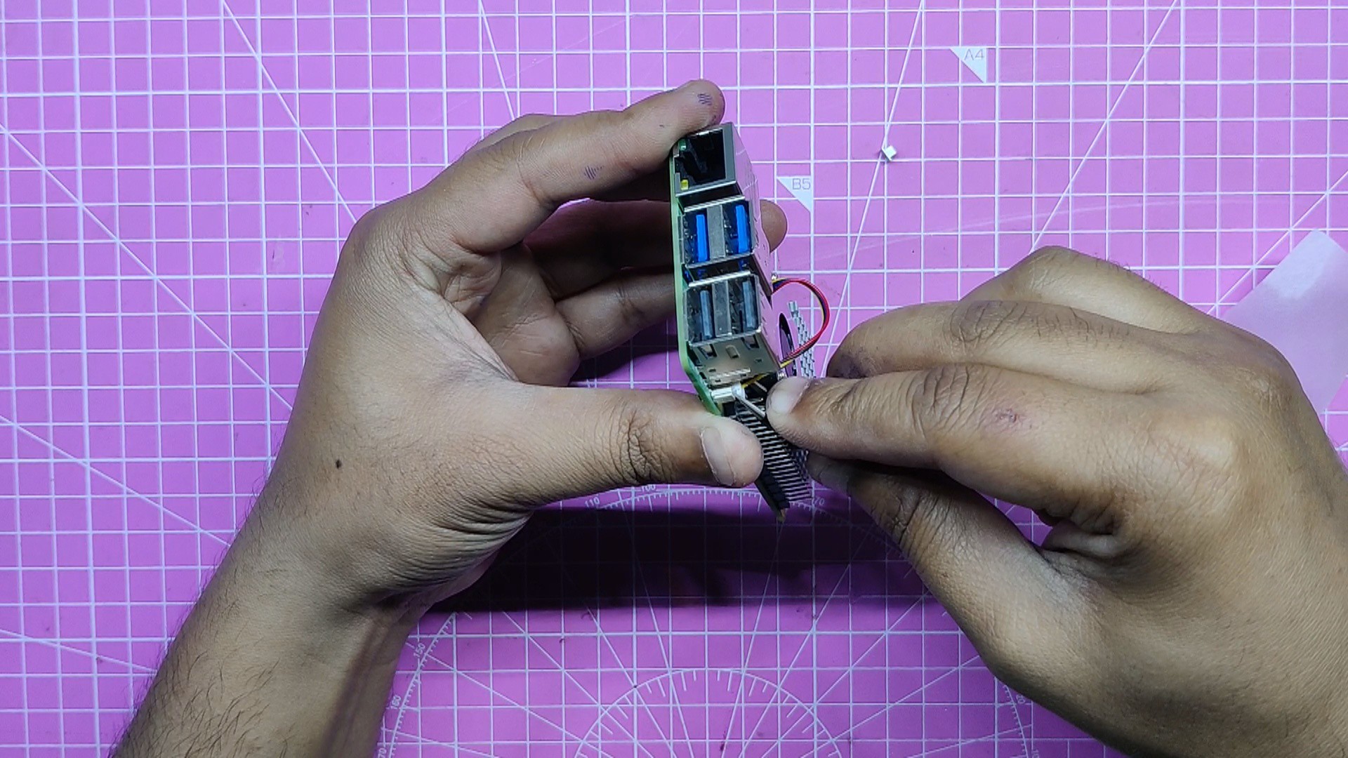
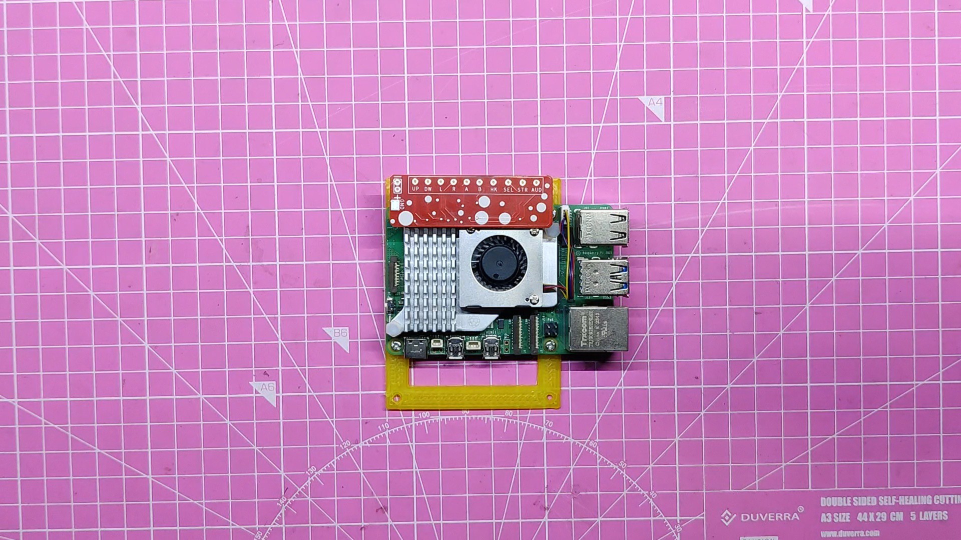
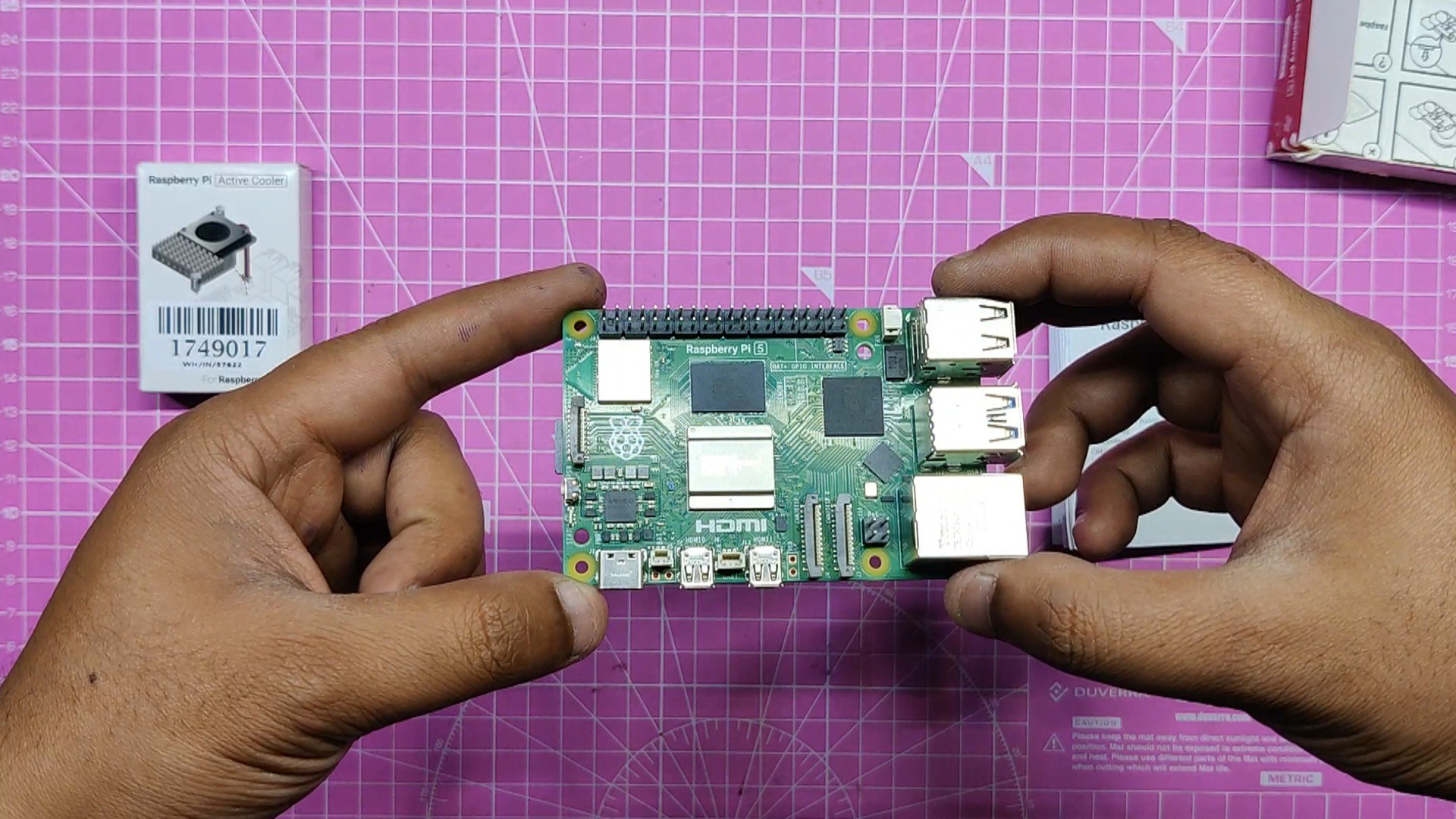
- The Raspberry Pi 5 was then attached to the Pi Holder part using four M2 screws to create the Pi Holder Assembly.
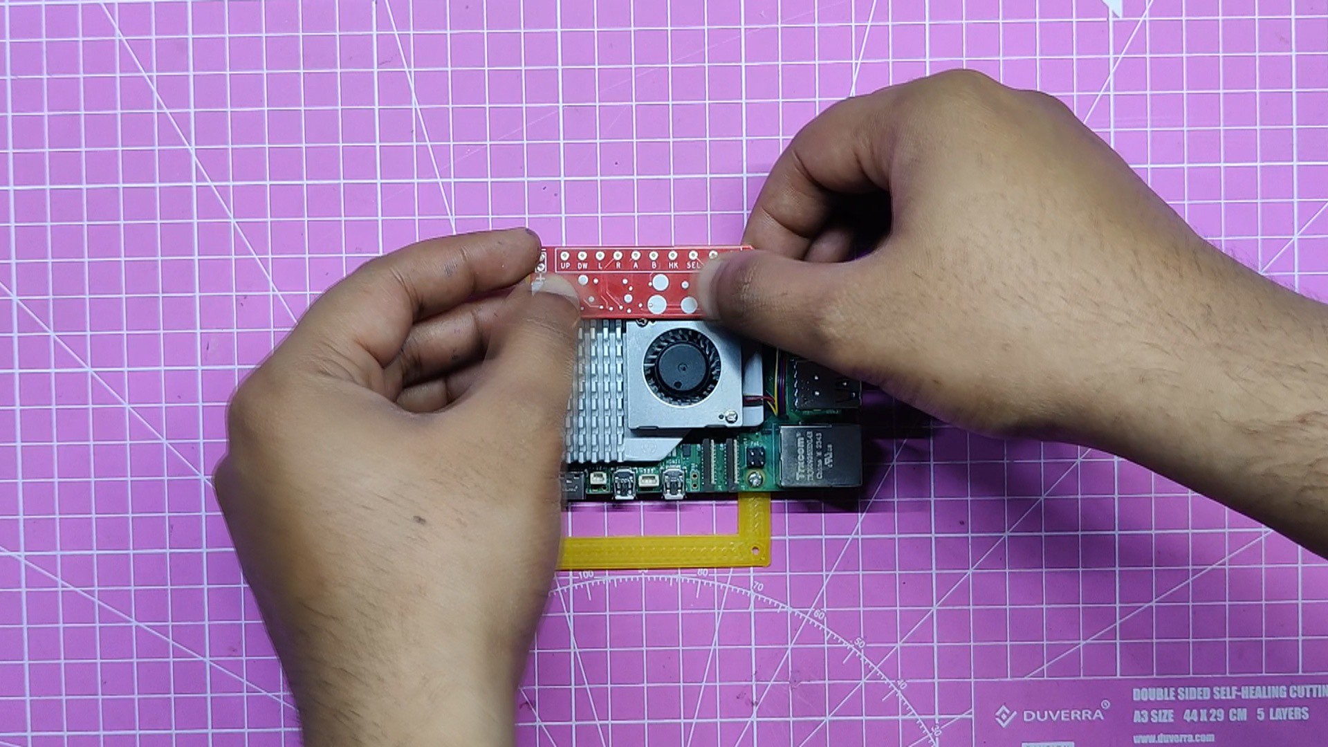
- Next, we attached the GPIO shield to the PI's GPIO header pins.
- This breakout board, called the GPIO shield, is used to connect button pins to the PI.
-
7Wiring
![]()
![]()
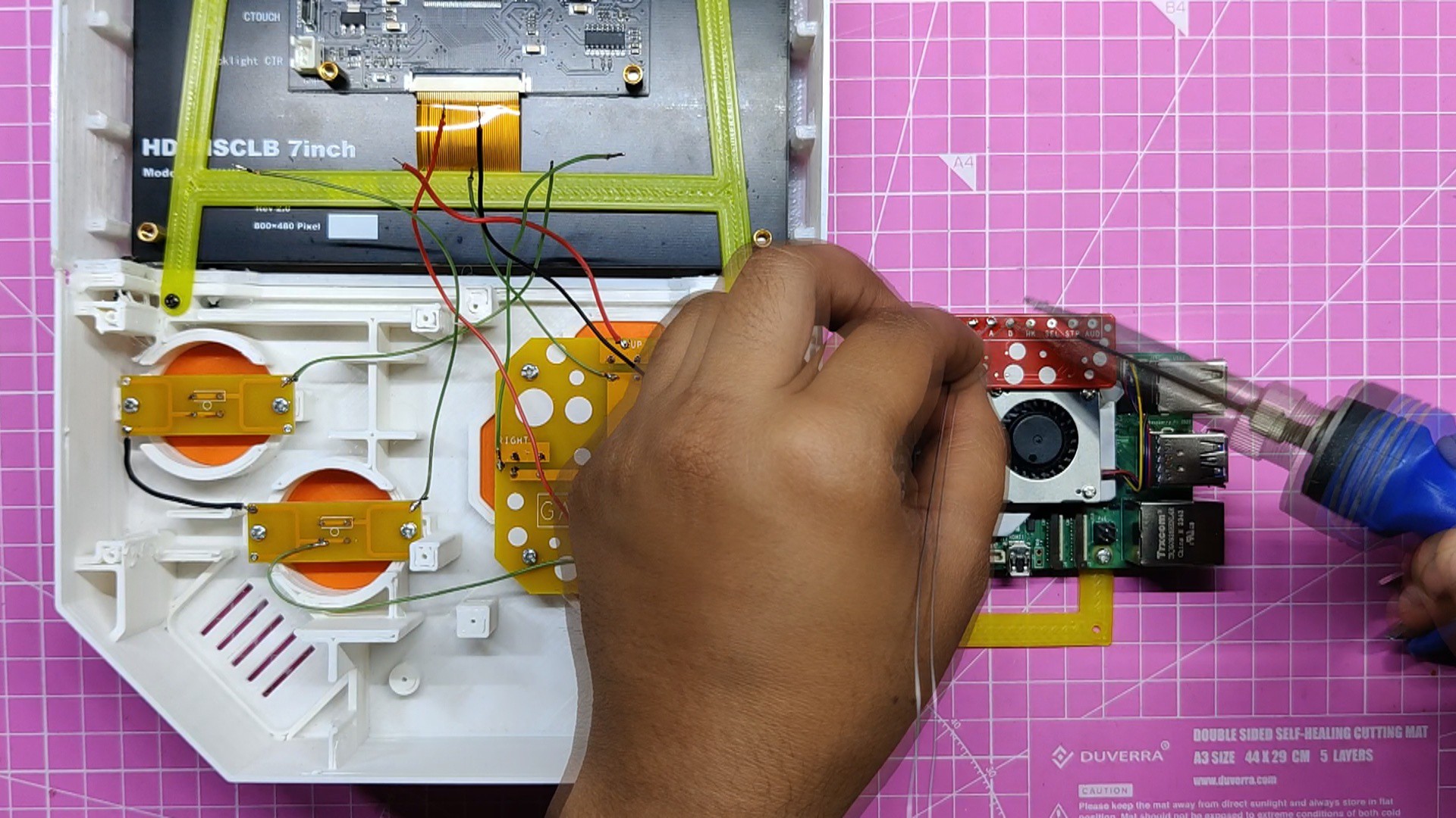
First, we connected one wire to each button output to prepare for wiring.
Additionally, we linked the A-B button PCB and the D pad PCB's GND together.
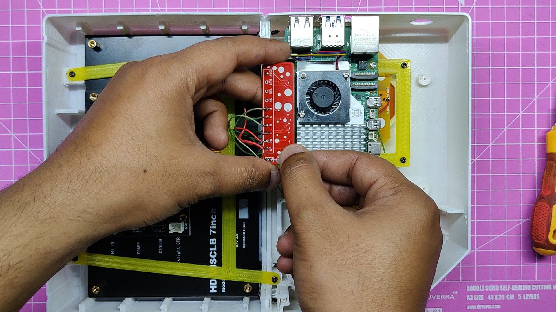
Next, we connect each button's wire with the Raspberry Pi GPIO Shield in the order below.
- UP Button-GPIO04
- DOWN Button-GPIO017
- LEFT Button-GPIO027
- RIGHT Button-GPIO022
- A Button-GPIO024
- B Button-GPIO025
-
8Adding Pi5
![]()
![]()
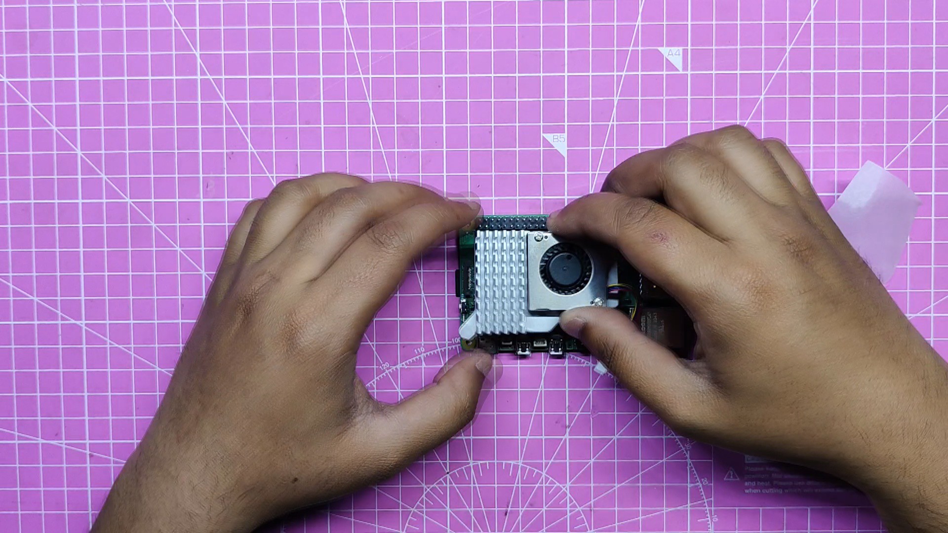
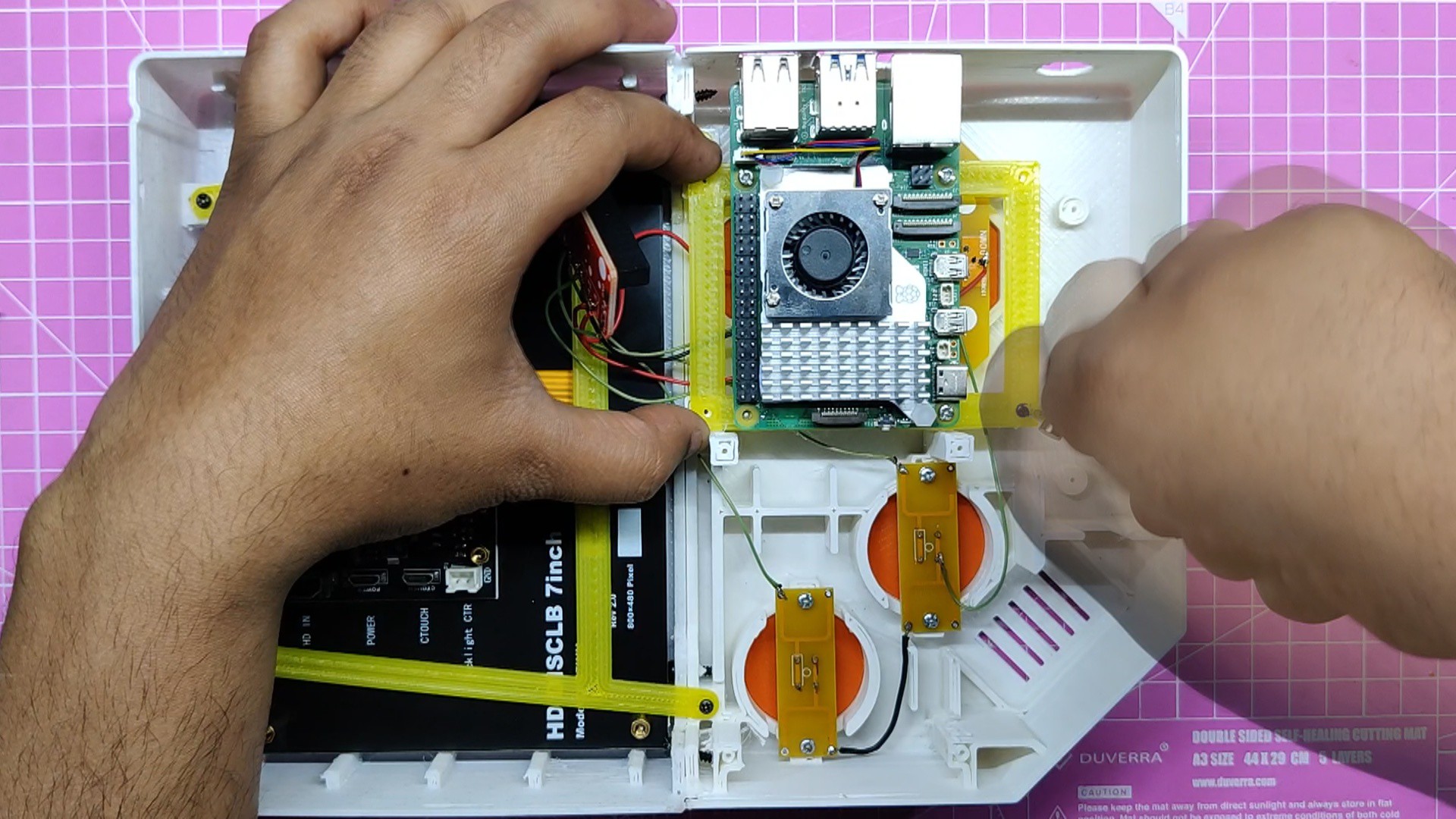
- The Pi is then mounted in its designated location, the Pi Holder Assembly is positioned there, and the GPIO Shield is detached because it is obstructing the mounting holes.
- To fasten the Pi Holder to the base body, we utilize M2 screws.
- We install the GPIO shield on the Pi once it is firmly in place.
-
9Audio Board
![]()
![]()
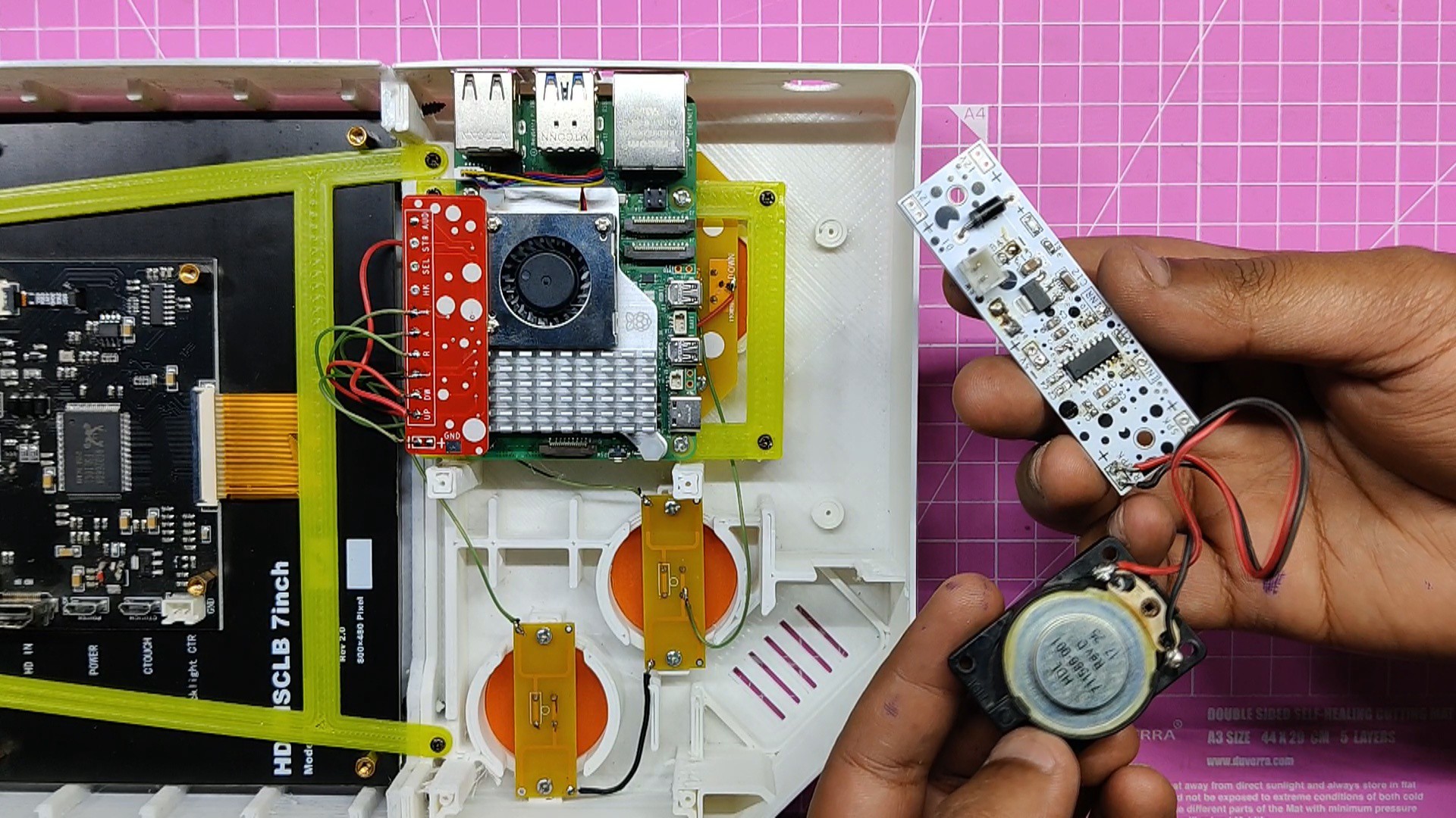
We are using a previously constructed Audio Board Project, for audio, which is a small amplifier based on the PAM8403 that has an extra AMS1117 voltage regulator built in to step down 12V input into 5V output for the 5V display and the audio amplifier.
checkout the project from here-
https://www.hackster.io/Arnov_Sharma_makes/diy-audio-amplifier-board-b03866
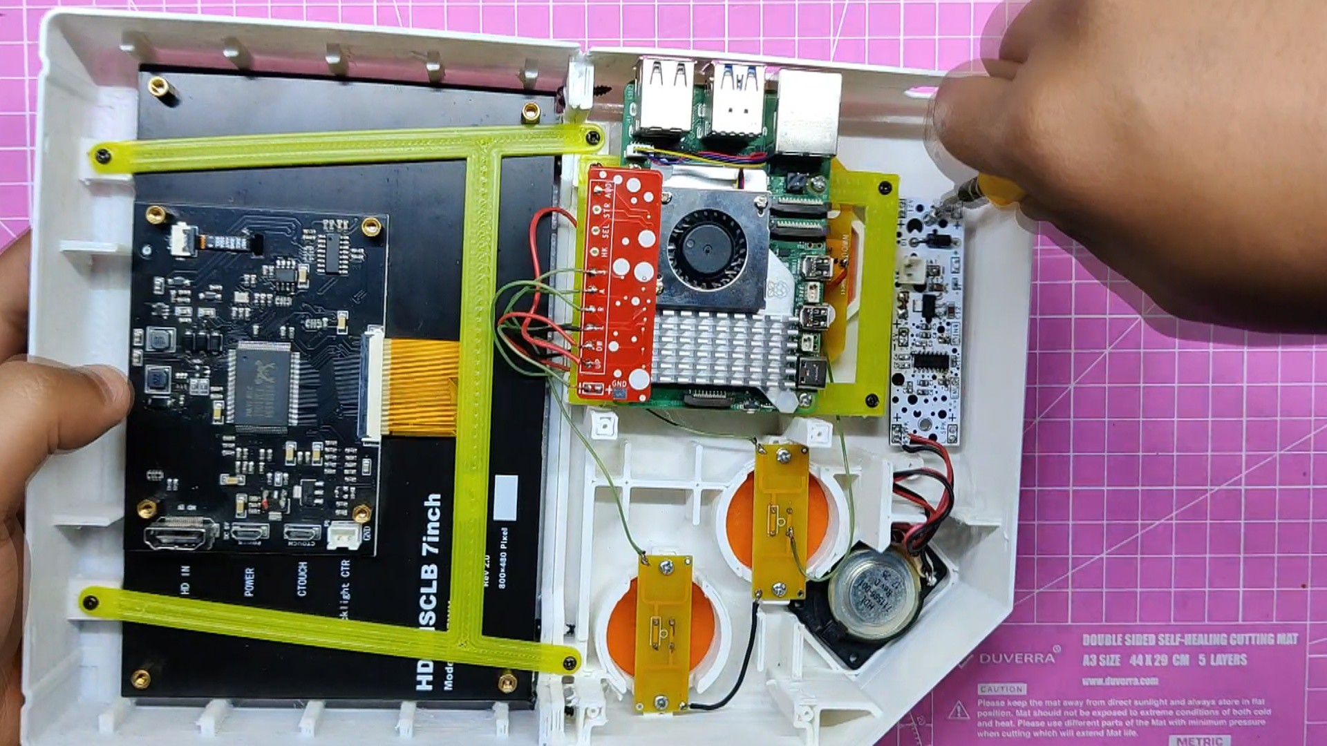
With the PCB for the audio amplifier in place, we install the speaker.
Next, we fasten the PCB using an M2 screw into the screw bosses that are provided on the body.
-
10Adding DC Jack- Charging Section-Power Section
![]()
![]()
![]()
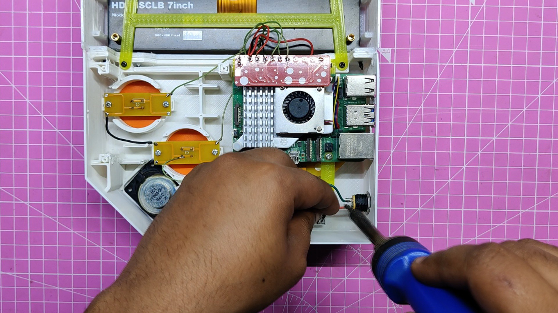
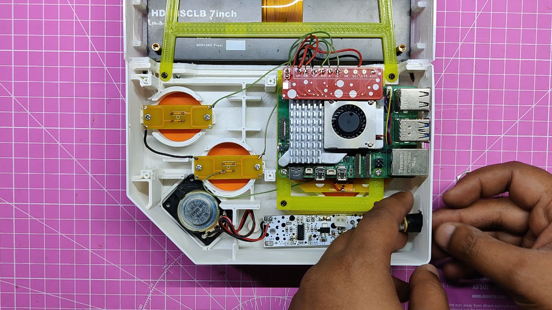
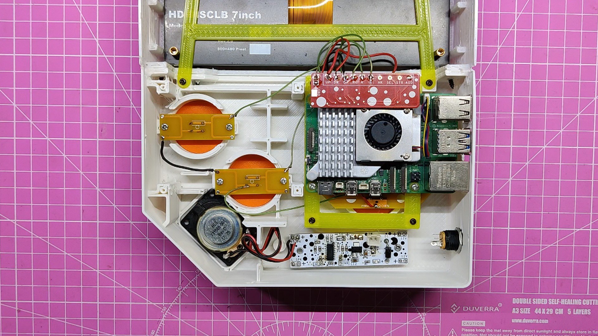
When DC Jack is fitted to any body, the nut portion that comes with the DC Barrel Jack tightens the DC Jack into place. DC Jack has been added to one side of the body.
Two wires are used to link the positive and negative terminals of the DC Jack to the charging port on the audio board.
After that, we attach a 12V adaptor to the DC Jack and measure the voltage across the 12V input side and the 5V output side of the AMS1117.
The battery pack will be charged using the 12V converter by placing it before the AMS1117 connector. The battery pack has a BMS, that will properly charge the cells, therefore an external 12V supply cut was not required in this instance.
Next, we linked the 5V of the audio board to the GND and the 5V of the display.
 Arnov Sharma
Discussions
Become a Hackaday.io Member
Create an account to leave a comment. Already have an account? Log In.