Elbert
-
Accurate scanning (unfortunately not...)
07/13/2024 at 12:21 • 0 commentsThe frames have to be moved very accurately; the next frame should overlap at the precise place, otherwise the final film will not be stable.
The problem was that I have one stepper motor at the tooth wheel and one stepper motor on the reel that winds up the film. The reel that provides the film is rotating freely. The tooth wheel was after the microscope. So there was no tension between the providing reel and the tooth wheel. The frame did not uniformly move forward. This gave random positions in the photographed image and no way to make a stable clip.
The proper design is to have the microscope between the tooth wheel and the receiving reel. In OpenScad I had to switch the tooth wheel and the microscope. And making sure that the screws did not interact with the other stuff. I had to make the base a little longer.
Unfortunately, I did not succeed with this setup either. The tension on the film was not consistent enough resulting in an inaccuracy up to 20% of the frame. The tooth wheel and the sensor were too far apart. So I could not rely on the mechanical accuracy. Software has to come to the rescue.
Instead of moving a complete frame, I let it move a third of a frame. The software will stitch these images together. A half frame movement would probably also work, but a third gives plenty of room for the stitching software. It is then very important to have equal lighting over the area of the frame, otherwise the light will jump from frame to frame.
Although I usually program in C++, the easiest way (at least I thought) was to use Python with openCV in the PyCharm editor. The thing I really like about PyCharm is that you can install the packages with a few clicks. OpenCV has a stitcher function and there is even an example program in the openCV documentation. I had the stitcher running within an hour. Unfortunately, the stitcher could not stitch the images. Even the example images from the documentation did not want to stitch. A long internet search gave a few possible solutions, but it still did not want to stitch, without further information. Maybe is was Python or the PyCharm packages. So I used the pre-compiles OpenCV libraries with C++. Again, the same result. The stitcher did not want to stitch.
So, there was nothing left then to write my own stitcher code. Which is not that difficult, but time consuming to get it right. I took a two step approach. First I stitch 4 images together. And then I search for the frame. The stitching is done by calculating the correlation between the two images with the latter shifted. The shift with the best correlation is then used. The correlation is simply the absolute difference of each of the red, green and blue value of the pixels. Having around 1 million pixels and 1000 possible shifts means to calculate 3 billion differences. But things can be done smarter. First we know that the frame has roughly moved a third of a frame. Secondly, we do not have to use all pixels, but can use a raster. This speeds up things a lot.
Once the shifts are known we can combine the pictures. If we we we have a pixel in different images, we can use the average values. One can argue that this also gives a sharper image, but this is probably not the case. After we have a stitched image we search for the tell-tales of the frame: black lines between the frames and a white hole for the tooth wheel. This is also done by scanning the image and correlate with this frame tell-tale. We have to measure the exact positions of the lines and holes. I wrote also a function to improve these values by using a frame and see whether the correlation improves when changing the values of the black lines and the tooth wheel a little.
This whole process is rather slow in Python, so I used C++. I also did not use OpenCV, but two simple jpeg libraries; Nanojpeg (actually the C++ version of Scott Graham) and Tinyjpeg (written by Sergio Gonzalez), and my own image class.
-
The control code
07/02/2024 at 20:19 • 0 commentsThe program on the laptop has the sequence of telling the ESP32 to forward a frame, wait till it is finished, take a picture with the microscope and repeat. The program can also forward the letters for the commands (AaBbCcDdEeFfGgWwXxYyZz) to the ESP32.
The program has therefore two modi: by pressing 1 it is in the forward mode and every letter that is pressed is sent to the ESP32 and the communication back is shown. By pressing 2 the digitizing sequence is started. Note: if you have changed the speed or acceleration, it will keep the change. Also when the program is restarted, the ESP32 cannot know and still will not reset the speed or acceleration. Only resetting the ESP32 module will revert to the standard settings. By pressing 3 the image counter of the digitizer will be set to zero. This can be pressed during both modi. So if the digitizing is in progress and 3 is pressed, the images start at zero again, overwriting the previous scanned images.
I am running the program on Linux Mint in a virtual box on the PC. We can forward the USB port to the virtual machine.
For some reason the program needs super user access to be able to communicate with the serial port. So it should be started with the sudo command.
For some other unknown reason, one in the 100 to 200 images scanned with fswebcam are black and the file size is small. Therefore I used a batch file to scan with fswebcam. After the image is scanned it will look at the file size of the image. If it is small (smaller than 40 kB) it will rescan. If one want to be really sure, one could even check the result of this scan (or even in a loop with a maximum) but chances are really low that a second scan will be black. Maybe you are thinking: what if the frame is black? We also scan the hole (we will see later why) and that is bright white.
The source files (the C++ file control.cpp and the bash file read_pict) are uploaded. Be aware: we should use the g++ compiler.
-
The ESP32 code
06/28/2024 at 15:53 • 0 commentsThe control program on the ESP32 communicates with the laptop through the serial port. It gets the commands with characters and communicates back when the stepper motor is finished. I kept it simple. The first command is to forward a frame. That is 'A'. The upper case letter is for the first stepper motor (the tooth wheel) and the lower case letter for the other stepper motor at the reel. 'B' and 'b: are a frame backward. Cc and Dd are for a single step. Ee and Ff for continuous turning. (And later Gg and HH for a third frame.) It replies with E1 and E2 when the turning is finished. (In hindsight I should have used E and e). Also the speed and the acceleration can be adjusted with WwXx for halving and doubling the acceleration and YyZz for the speed.
A friend once told me: don’t write any code yourself; everything is already written. That’s true. For every task several libraries have been written and the Arduino IDE let you choose the one you like. The most time goes into choosing the library.
An important condition is to be able to have two stepper motors turning simultaneously. So the routines should be non-blocking. I settled for AccelStepper. It also has the nice feature that it can slowly accelerate and decelerate. In this way the film is protected against a too aggressive tooth wheel.
The only function missing is a callback function when the stepper motor is finished turning. I wanted to include ths function using inheritance, but for some unknown reason I did not get this working, even after trying for a whole evening. So I went for the quick and dirty way to just add functions and duplicate them for the two steppers.
The ESP32 source code is in the file section.
-
The control electronics
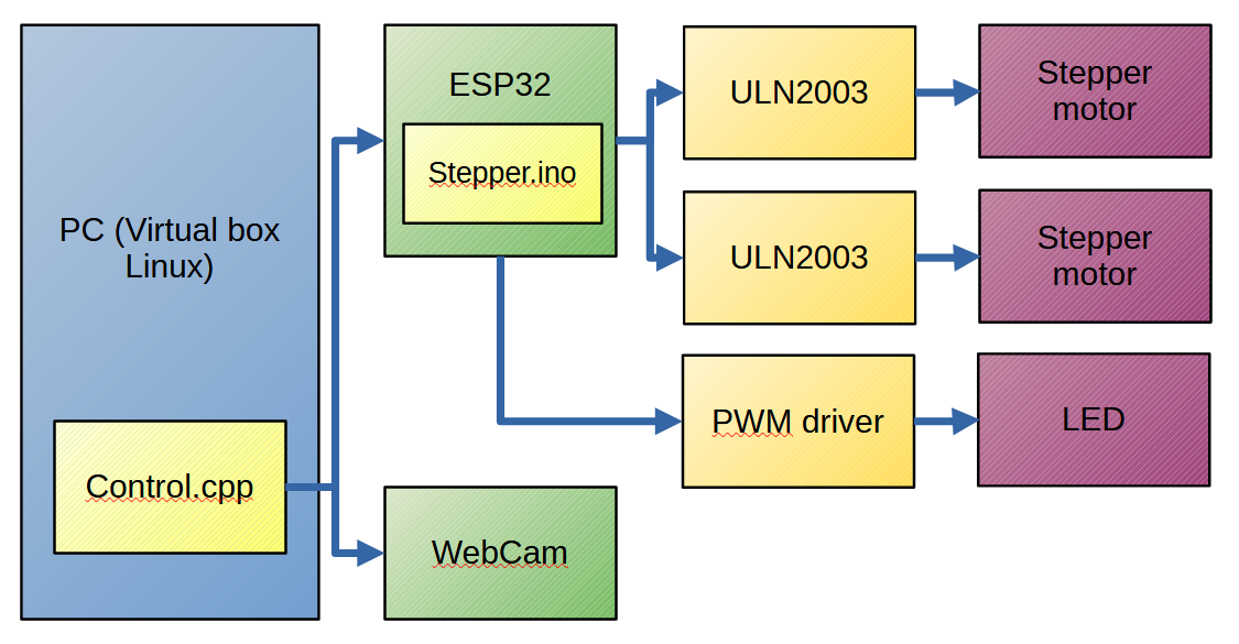
05/22/2024 at 20:07 • 0 commentsThe control of the digitizer consists of a PC (laptop) running (through Virtualbox) Linux mint. A C++ program (control) reads the serial port of the ESP32 and captures the frame by invoking the fswebcam program to get a picture from the microscope.
The ESP32 runs a program (stepper) which gets commands through the serial ports to run the stepper motors and sends back a notification when the stepper motor has reached its target position.
A variable PWM module (powered from the ESP32) controls the strength of the LED.
-
The first prototype
05/20/2024 at 20:26 • 0 commentsFor a first try, I take the configuration of the manual viewer as layout. I need two stepper motors. The first one is connected to the wheel with tooth that grab into the holes in the film. It has 12 tooth, so 1/12 turn of this wheel advances one frame. The second stepper motor (although it could have been a normal motor) turns the spool. It should be able to slip, so I made a few different clutches.
I used the simple 28BYJ-48 geared stepper motors with ULN2003 drivers.
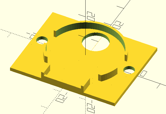
I made a frame and holders for the stepper motors in OpenScad and sliced it with Cura.
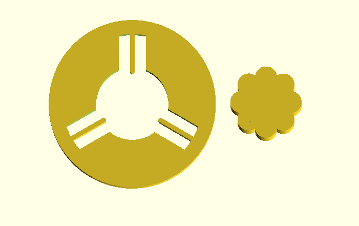
The best clutch was an outer ring with spring-like pins, and an inside wheel with an curved surface.
![]()
Problems with this first prototype:
- The film was too loose around the wheel, so it slipped.
- The microscope holder was off.
- And it was too dense to tweak.
So the second prototype has to be wider, several options for the guarding wheels to get enough tension, and a proper place for the microscope.