 TJ
TJBlock Diagram
Decided on making a VU Meter. Below is the inital block diagram of the system.
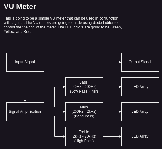
The filter cutoff frequencies were taken from https://www.amplifiedparts.com/tech-articles/audible-frequency-range-and-describing-tone.
Board Layout
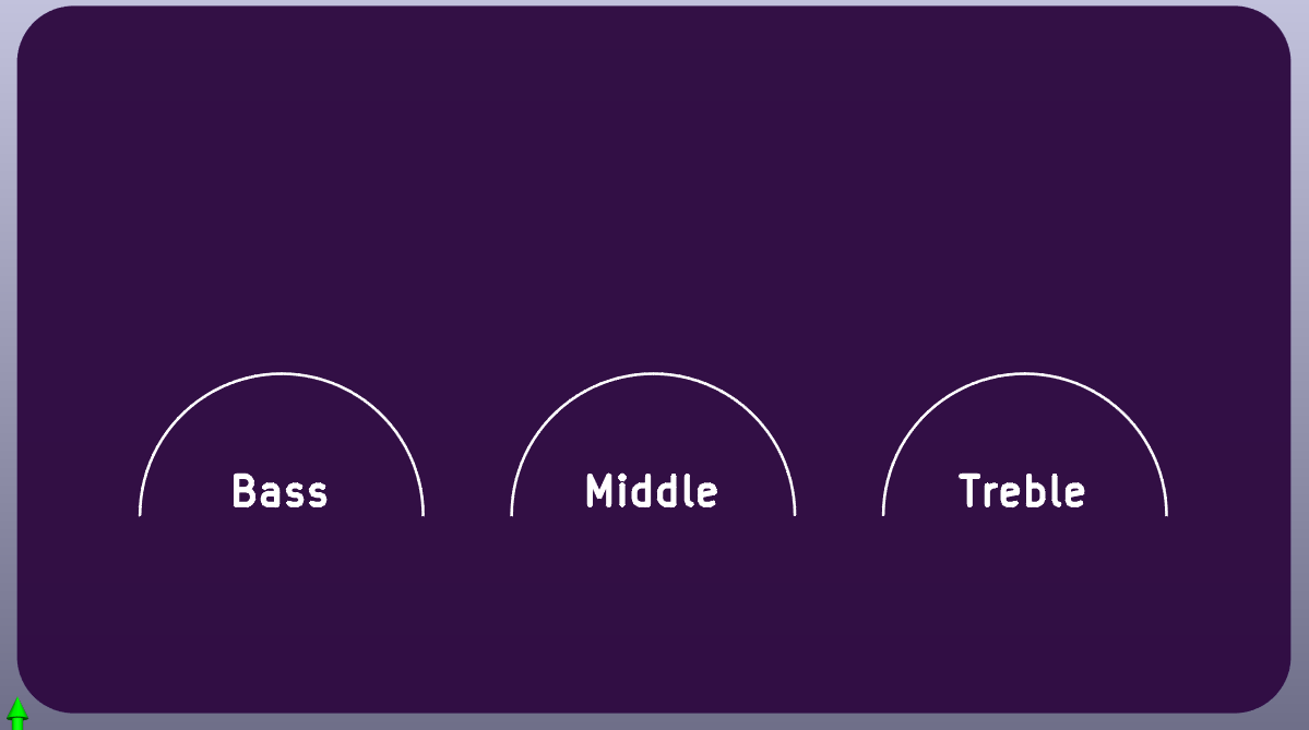
Started to layout the graphics for the VU meters. The VU meter is going to be a half-circle with the specific tonal bands labeled in the middle of the half-circle.
Discussions
Become a Hackaday.io Member
Create an account to leave a comment. Already have an account? Log In.