 TJ
TJBoard Layout
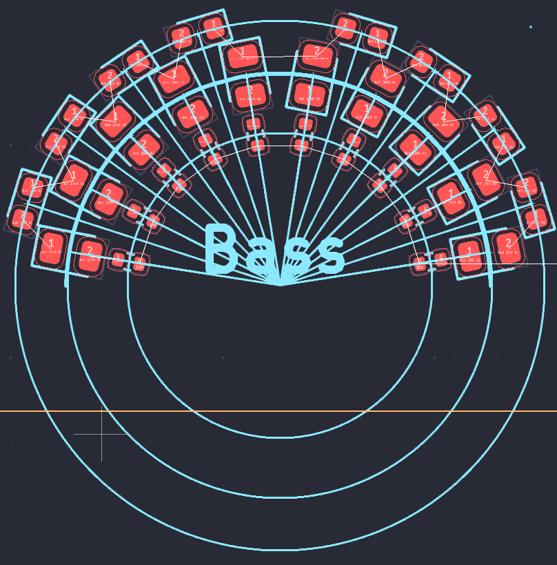
Spent most of the day working on laying out the VU meter components along the half-circle. This was before I finalized the component selection for the LEDs and the diode ladder.
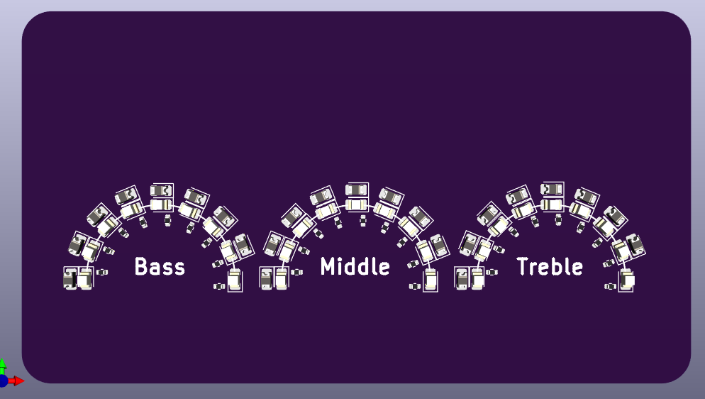
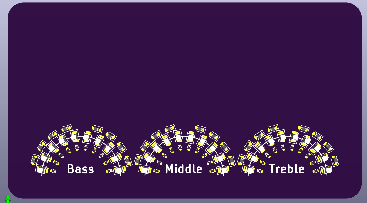
For the final layout, I changed the orientation of the LEDs. I also used lines from the center of the half-circle. The angle between the LEDs is about 18 degrees with an 9 degree offset from 0 and 180 degrees.
After laying out the components. I moved the VU meters lower down the card.
Discussions
Become a Hackaday.io Member
Create an account to leave a comment. Already have an account? Log In.