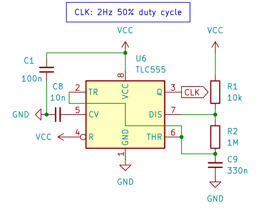
For clock signal I'm using 555 timer. There are lots of tools online for calculating 555 timer circuit parameters. I used 555 Astable Circuit Calculator for this.
General rules are:
- choose R2 value much higher than R1 for 50% duty cycle;
- C9 sets clock frequency. 330nF capacitor will generate 2Hz signal. To increase frequency, decrease C9 value.

For generating 5-bit logic circuit input signal we'll need binary counter. It will divide clock signal frequency by 2/4/8/16 and so on.
Full circuit simulation with 555 clock generator, binary counter and logical circuit was done using Falstad. Click here to access it.
 Martynas
Discussions
Become a Hackaday.io Member
Create an account to leave a comment. Already have an account? Log In.