 cheetah_henry
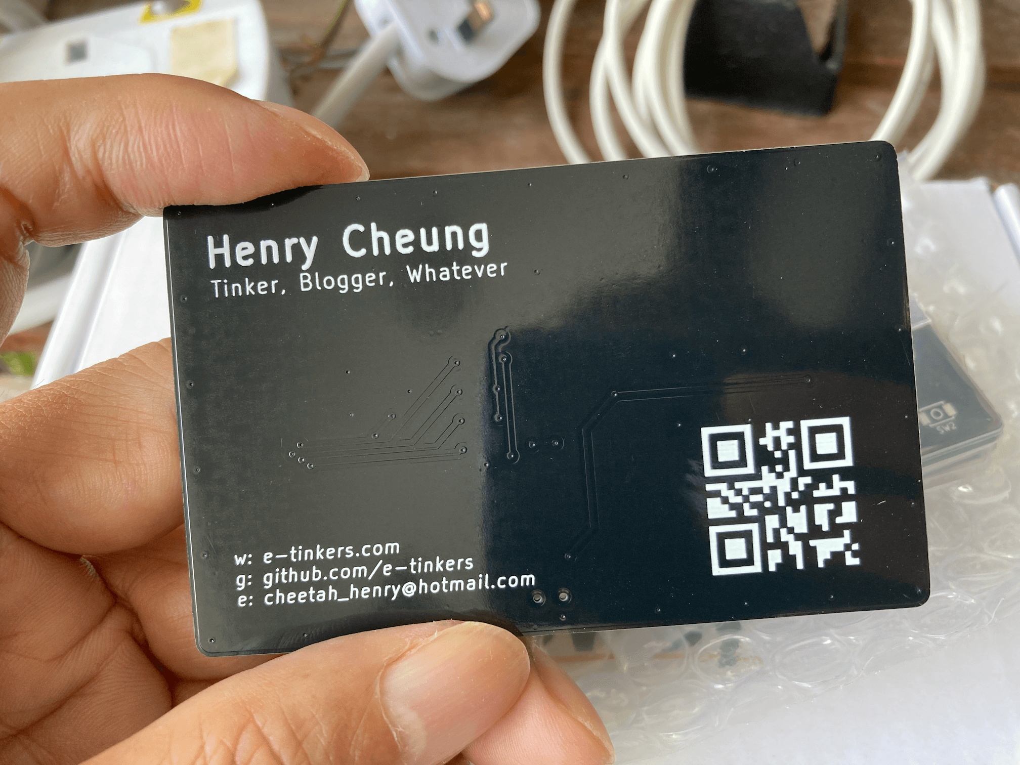
The PCB has arrived from PCBWay. It looks great with the black background.
PCB Front
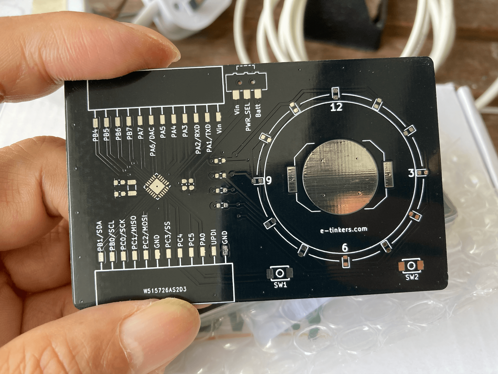
PCB Component Side
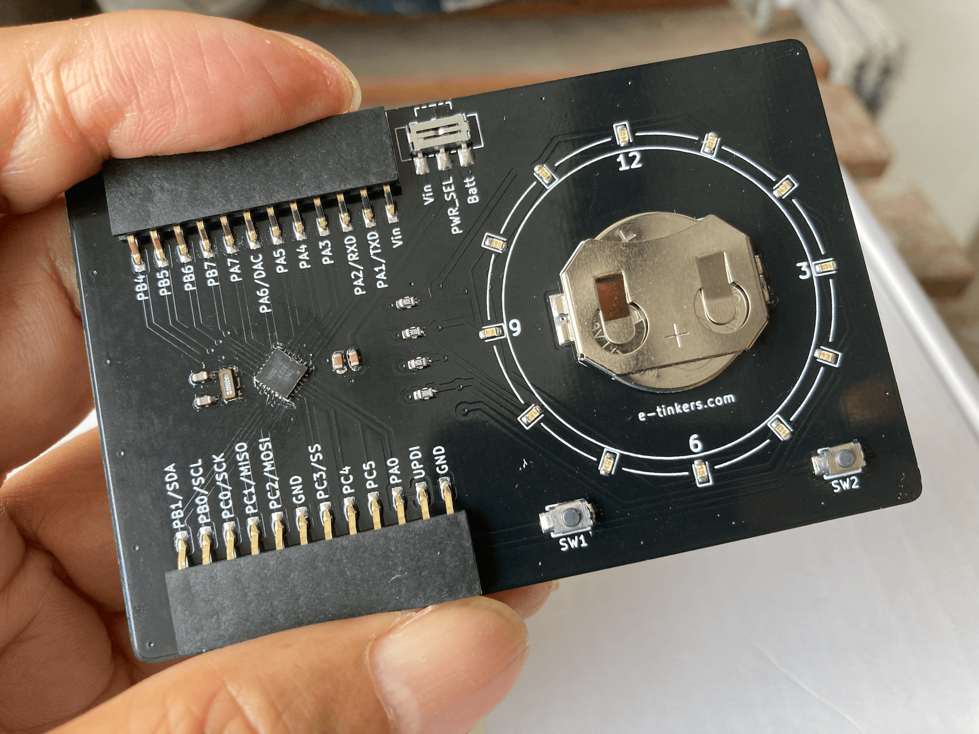
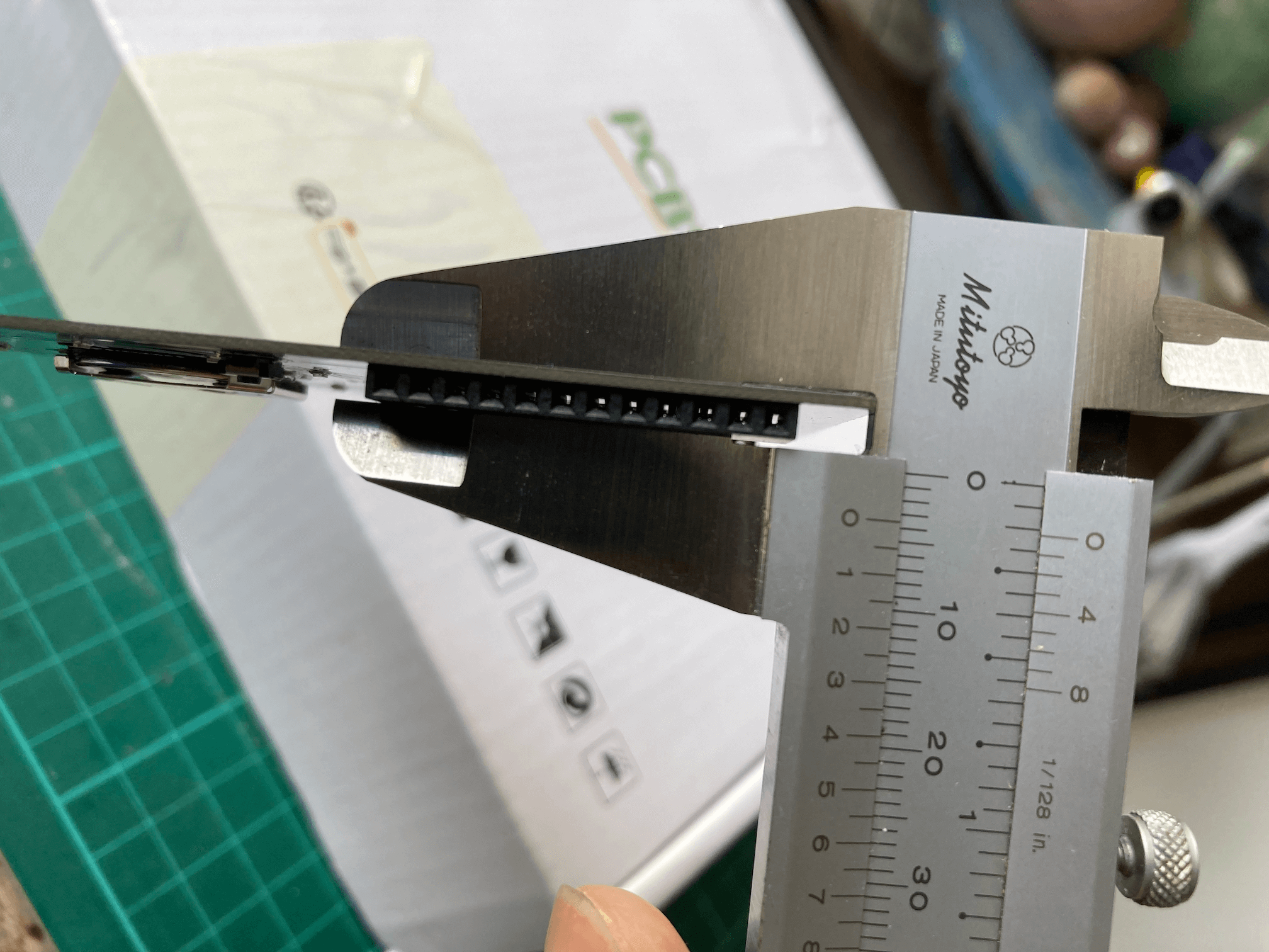
Since the VQFN package of ATtiny3227 is only 4 x 4 mm, so I ordered the stencil. The final assembly looks great. PCB thickness measurement shows that it is 3.2mm at the battery holder and 3.4mm at the break-out connector side.
PCB after assembly
PCB Thickness Measure
Everything work fine, this including the software as well as the hardware design. Here is a gif of the clock showing time at 4:39
and at 4:45
The project is very much completed by now. I think that I will add one or two logs later on how I setup the toolchain and provide a couple of demonstration on how to use the business card as a ATtiny3227 development board.
Discussions
Become a Hackaday.io Member
Create an account to leave a comment. Already have an account? Log In.