 cheetah_henry
The schematic is quite similar to my NTP Clock project, consists of 12-LED with charlieplexing, minus the charging circuit, and replace the power hungry ESP8266 with an ATtiny3227 tinyAVR 2-series MCU, with all the pins break-out.
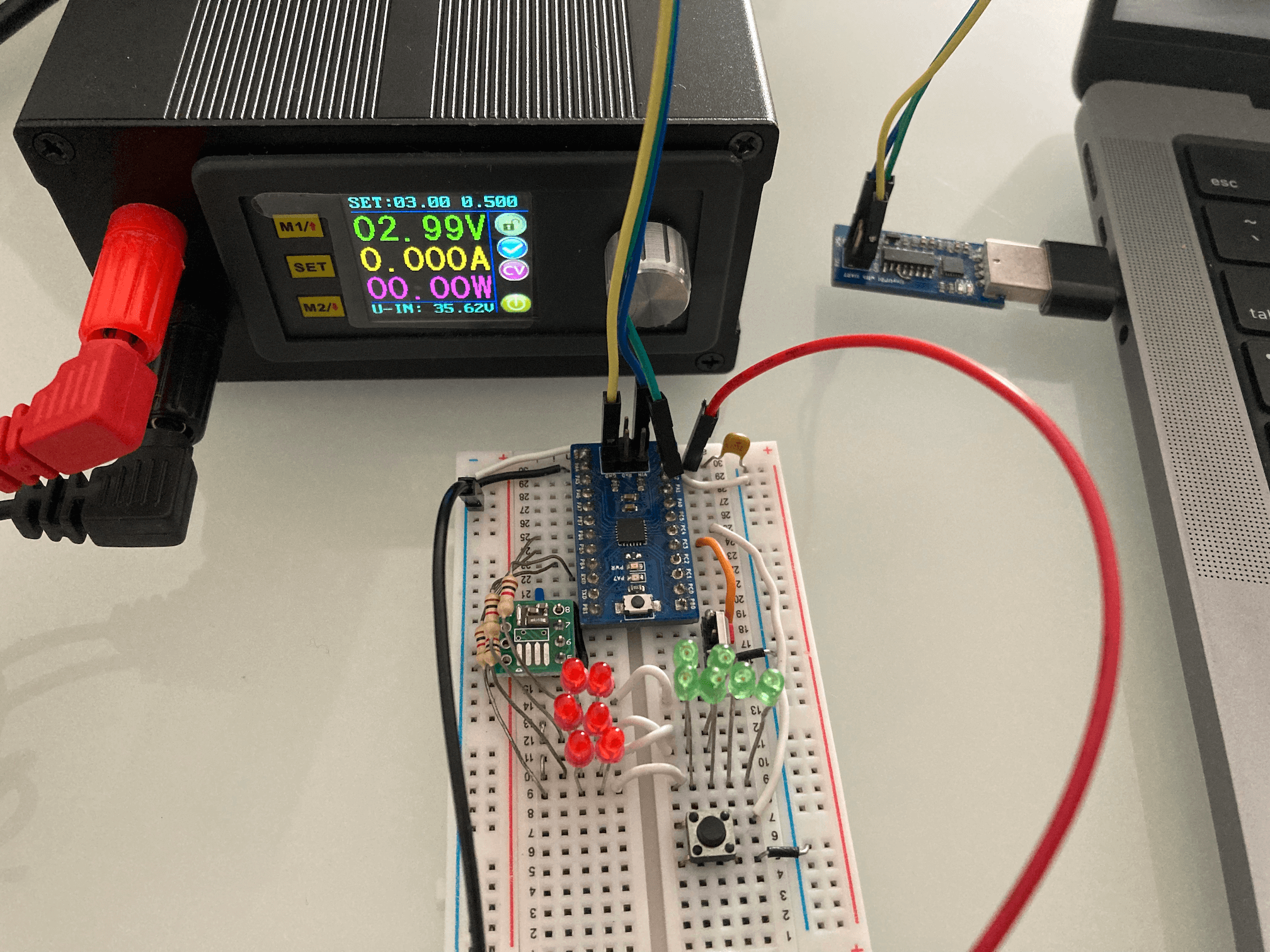
I setup a test environment which consists of an ATtiny3227 development board, and external 32.768kHz crystal oscillator, and 12 LEDS (I don't have sufficient red LEDs, so the test setup consists of 6 red LEDs and 6 green LEDs).
I will further explain the hardware design in later logs whenever appropriate when discussing any design considerations. For now, I will talk about the BOM cost and the ATtiny3227 Power Down Mode and the tests that I have done in order to determine the battery life for the Business Card.
BOM
The BOM cost is calculated based on sourcing from DigiKey since they are the sponsor of the 2024 Business Card Challenge contest, with the exception of a couple of components. The SPDT switch and the CR2016 battery holder are based on a component that that I already have with me that were sourced from LCSC, similar part can be found in DigiKey but the footprint might not be 100% align with the parts that I have. Two SMD 1x12 Connector Female Socket are also based on LCSC price as I can't find the identical part from DigiKey. Maybe I didn't find harder enough. The total BOM cost is around $8 including CR2016 as well as an estimated PCB fabrication cost/piece. The cost of PCB is estimated based on PCBWay's fabrication costs of $5 for 10 pcs, so each piece is at $0.5 and used as the BOM cost.
ATtiny3227 Power Down Mode
Before creating PCB or writing software, it is important to understand the power consumption of the circuitry at both active mode and sleep mode, and confirm some of the assumptions that I made in battery life as I planned to use CR2016 which only has the capacity of 98mAh. The bigger battery CR2032 would have a bigger capacity of 235mAh, but the thickness increased. I want to have the business card with slim profile, CR2016 with the battery holder will have a thickness of 2.2mm as compare to the CR2032 one of 3.6mm, without including the PCB thickness which will add another 1mm.
The first thing I did is to determine the system clock speed that I should used for the design. For Modern AVR chips (Refer to ATtiny 0, 1 and 2-series, ATmega 0-series, and AVR Dx series), all clocks are active in active mode, and the CPU is running. Power consumption in active mode is proportional to the operating frequency of the system clock. As the charlieplexing clock does not demand high-frequency operation, and therefor can benefit from lowering the system clock.
The ATtiny3227 (this applies to the entire ATtiny 0, 1 and 2-series) can operate at 20MHz with a Low-Power internal oscillator without the need for external crystal. This oscillator can operate at multiple frequencies, selected by the value of the Frequency Select bits (FREQSEL) in the Oscillator Configuration Fuse (FUSE.OSCCFG). So I configure the clock to run at 20MHz, 10MHz and 5MHz and write a simple program to test the current consumption at ative mode.
In order to simulate the usage of the actual application, I config the RTC to wake up on every second to increment the `timeCount` which is going to be used for keeping the time in seconds. In order to make sure that the configuration of the RTC work as expected, I initially also config the PORTA PIN7 (which has an LED attached to it on the ATtiny3227 development board) so that it will toggle the LED on every wake-up, once I know the RTC is working, I then comment out the PORTA configuration so that I can measure the current without affecting by the LED blinking.
#include <avr/io.h>
#include <avr/interrupt.h>

volatile uint32_t timeCount = 0;

ISR (RTC_PIT_vect) {
  timeCount = (timeCount + 1) % 43200; // count up to 12-hour (12 * 3600) = 43200
  // PORTA.OUTTGL = PIN7_bm;
  RTC.PITINTFLAGS = RTC_PI_bm; // Clear periodic interrupt flag
}

void configRTC() {
  /* Using external 32.768kHz clock on PB2 and PB3 */
  _PROTECTED_WRITE(CLKCTRL.XOSC32KCTRLA, CLKCTRL_RUNSTDBY_bm | CLKCTRL_ENABLE_bm);
  while (RTC.STATUS > 0);
  RTC.CLKSEL = RTC_CLKSEL_TOSC32K_gc; // clock from XOSC32K (PB2 & PB3) or TSOC1 pin (PB3)

  RTC.PITCTRLA = RTC_PERIOD_CYC32768_gc | RTC_PITEN_bm; // RTC clock cycles between each interrupt
  RTC.PITINTCTRL = RTC_PI_bm;

}

int main() {
  _PROTECTED_WRITE(CLKCTRL_MCLKCTRLB, (CLKCTRL_PEN_bm | CLKCTRL_PDIV_4X_gc)); // running at 20/4 = 5MHz
  // PORTA.DIRSET = PIN7_bm;
  configRTC();
  sei();
  while(1) {
  }
  return 0;

}
Here is the result of current consumptions for various operating voltages at different clock speeds. Current consumption at 2V is measured because at 2V the CR2016 battery is likely running out of power even though the ATtiny3227 is capable operate at 1.8v.
| Operating Voltage | 20MHz | 10MHz | 5MHz |
| 5V | 10.5mA | 6.1mA | 3.7mA |
| 3V | 4mA | 3.1mA | 1.8mA |
| 2V | 2.47mA | 1.4mA | 1.2mA |
These values are meausured when the LED is off, I further test the LED current consumption. At 3V operation at 5MHz clock speed, the current consumption increased from 1.8mA to 2.35mA with the LED turn on. The LED is connect to between the GPIO pin and GND via a 2k-ohm resistor. The published current consumption on ATtiny3227 datasheet for the same operation condition is showing as 2mA typical so the measurement is inline with the datasheet.
This table shows that the operating voltage affects the power consumption greatly. The Business Card design should definitely set to operate at 5MHz instead of 20MHz.
In additonal to the 20MHz main clock, there is another 32.768kHz internal clock for RTC (Real-Time Counter). The 32.768kHz oscillator is optimized for Ultra Low-Power (ULP) operation. "Power consumption is decreased at the cost of decreased accuracy compared to an external crystal oscillator" as per Microchip Application Note. Since the Business Card is a real-time Clock/watch, Ideally I'd want to have an accurate 32,768kHz clock base than the internal "decreased accuracy" clock. So I solder an Seiko Epson 32.768kHz 20ppm crystal together with two 18pF capacitor to a break-out board and connected to the TOSC1 and TOSC2 pins of the ATtiny3227, and program the ATtiny3227 to use either the internal oscillator or the external crystal, I modified the code slightly to configure the ATtiny3227 to use either the Internal Oscillator or the external crystal clock with a macro `USE_INTERNAL_OSC`.
#define USE_INTERNAL_OSC

void configRTC() {

#if defined(USE_INTERNAL_OSC)
  /* Using ULP internal 32.768kHz clcok */
  while (RTC.STATUS > 0);
  RTC.CLKSEL = RTC_CLKSEL_INT32K_gc; // 32.768kHz Internal Oscillator
#else
  /* Using external 32.768kHz clock on PB2 and PB3 */
  _PROTECTED_WRITE(CLKCTRL.XOSC32KCTRLA, CLKCTRL_RUNSTDBY_bm | CLKCTRL_ENABLE_bm);
  while (RTC.STATUS > 0);
  RTC.CLKSEL = RTC_CLKSEL_TOSC32K_gc; // clock from XOSC32K (PB2 & PB3) or TSOC1 pin (PB3)
#endif
  RTC.PITCTRLA = RTC_PERIOD_CYC32768_gc | RTC_PITEN_bm; // RTC clock cycles between each interrupt
  RTC.PITINTCTRL = RTC_PI_bm;

}
I don't see any noticable difference in current consumption between using the internal oscillator and using the external crystal. So this is a good news and answered one of my questions in crystal selection and the use of external RTC clock.
The next test is to evaluate the sleep mode performance of ATtiny3227. ATtiny3227 has three different sleep modes.
- Idle: The CPU stops executing code, resulting in reduced power consumption. All peripherals are running, and all interrupt sources can wake the device.
- Standby: All high-frequency clocks are stopped apart from any peripheral or clock that are enabled to run in Standby sleep mode. A subset of interrupt sources can wake the device.
- Power Down: All high-frequency clocks are stopped, only the PIT functionality(as part of RTC) is available, plus a few interrupt sources can wake the device.
I extend the code to configure the Power Down mode to operate at 5MHz main clock speed, the current consumption during the Power Down sleep mode is 88uA, this is way much higher than what is showing on the datasheet Table 33-5 (Power Consumption in Active, Idle, Power-Down, Standby and Reset Mode) of 1uA! So what is going on?
int main() {
  _PROTECTED_WRITE(CLKCTRL_MCLKCTRLB, (CLKCTRL_PEN_bm | CLKCTRL_PDIV_4X_gc)); // running at 20/4 = 5MHz
  SLPCTRL.CTRLA = SLPCTRL_SMODE_PDOWN_gc; // config sleep controller powerdown mode
  // PORTA.DIRSET = PIN7_bm;
  configRTC();
  sei();
  while(1) {
    SLPCTRL.CTRLA |= SLPCTRL_SEN_bm;  // sleep enable, this is equivalent to sleep_enable()
    __asm("sleep");                   // this is equivalent to sleep_cpu()
    SLPCTRL.CTRLA &= ~SLPCTRL_SEN_bm; // sleep disable , this is equivalent to sleep_disable()
  }
  return 0;

}
According to Microchip Application Note AN2515 AVR Low Power Techniques, it suggests to reset all the unused pins (i.e. set it to input), and enabled the internal pull-up resistor on each pin. So I modified the code to config each of the GPIO pins like so before enabling the sleep mode:
PORTA.OUTCLR = PIN0_bm;            // clear PORTA, PIN0
PORTA.PIN0CTRL = PORT_PULLUPEN_bm; // enable PULLUP
The current consumption drop to 56uA from previous 88uA, still not near to the 1uA?!
Microchip application note mentioned "In addition, disabling the digital input buffer on unused pins will further lower the power consumption." without much explanation. So I modified the code again to disable the input buffer and kept the pull-up enabled:
PORTA.OUTCLR = PIN0_bm;                                                                                  // clear PORTA, PIN0
PORTA.PIN0CTRL = PORT_PULLUPEN_bm | PORT_ISC_INPUT_DISABLE_gc; // enable PULLUP and disable the input buffer
The current drop from 56uA to 36uA, hmm... it looks like disable the input buffer does has the effect of reducing the current consumption, so maybe the 36uA was due to the leakage due to the pull-up resistors? I decided to give it a try to just disable the input buffer without the pull-up.
PORTA.OUTCLR = PIN0_bm;                                          // clear PORTA, PIN0
PORTA.PIN0CTRL = PORT_ISC_INPUT_DISABLE_gc; // disable the input buffer
Bingo! It shows a current consumption of 1uA at Power Down mode! So to summarize all the tests that I've done:
| Power Down Mode | Current at 3V/5MHz |
| With only PD setup | 88uA |
| With all pins set to INPUT and enable PULL-UP | 56uA |
| With all pins set to INPUT and PULL-UP + disable input buffer | 36uA |
| With all pins set to INPUT and disable input buffer | 1uA |
and the final test code that I used:
void turnOffAllPins() {
  // set all pin to input
  PORTA.DIRCLR = PIN0_bm | PIN1_bm | PIN2_bm | PIN3_bm | PIN4_bm | PIN5_bm | PIN6_bm | PIN7_bm;
  PORTB.DIRCLR = PIN0_bm | PIN1_bm | PIN2_bm | PIN3_bm | PIN4_bm | PIN5_bm | PIN6_bm | PIN7_bm;
  PORTC.DIRCLR = PIN0_bm | PIN1_bm | PIN2_bm | PIN3_bm | PIN4_bm | PIN5_bm;
  // disable input buffer to lower power consumption in sleep mode
  PORTA.PIN0CTRL = PORT_ISC_INPUT_DISABLE_gc;
  PORTA.PIN1CTRL = PORT_ISC_INPUT_DISABLE_gc;
  PORTA.PIN2CTRL = PORT_ISC_INPUT_DISABLE_gc;
  PORTA.PIN3CTRL = PORT_ISC_INPUT_DISABLE_gc;
  PORTA.PIN4CTRL = PORT_ISC_INPUT_DISABLE_gc;
  PORTA.PIN5CTRL = PORT_ISC_INPUT_DISABLE_gc;
  PORTA.PIN6CTRL = PORT_ISC_INPUT_DISABLE_gc;
  PORTA.PIN7CTRL = PORT_ISC_INPUT_DISABLE_gc;

  PORTB.PIN0CTRL = PORT_ISC_INPUT_DISABLE_gc;
  PORTB.PIN1CTRL = PORT_ISC_INPUT_DISABLE_gc;
  PORTB.PIN2CTRL = PORT_ISC_INPUT_DISABLE_gc;
  PORTB.PIN3CTRL = PORT_ISC_INPUT_DISABLE_gc;
  PORTB.PIN4CTRL = PORT_ISC_INPUT_DISABLE_gc;
  PORTB.PIN5CTRL = PORT_ISC_INPUT_DISABLE_gc;
  PORTB.PIN6CTRL = PORT_ISC_INPUT_DISABLE_gc;
  PORTB.PIN7CTRL = PORT_ISC_INPUT_DISABLE_gc;

  PORTC.PIN0CTRL = PORT_ISC_INPUT_DISABLE_gc;
  PORTC.PIN1CTRL = PORT_ISC_INPUT_DISABLE_gc;
  PORTC.PIN2CTRL = PORT_ISC_INPUT_DISABLE_gc;
  PORTC.PIN3CTRL = PORT_ISC_INPUT_DISABLE_gc;
  PORTC.PIN4CTRL = PORT_ISC_INPUT_DISABLE_gc;
  PORTC.PIN5CTRL = PORT_ISC_INPUT_DISABLE_gc;

}

int main() {
  _PROTECTED_WRITE(CLKCTRL_MCLKCTRLB, (CLKCTRL_PEN_bm | CLKCTRL_PDIV_4X_gc)); // running at 20/4 = 5MHz
  // PORTA.DIRSET = PIN7_bm;
  configRTC();
  sei();
  while(1) {
    turnOffAllPins();
    SLPCTRL.CTRLA |= SLPCTRL_SEN_bm;  // sleep enable, this is equivalent to sleep_enable()
    __asm("sleep");                   // this is equivalent to sleep_cpu()
    SLPCTRL.CTRLA &= ~SLPCTRL_SEN_bm; // sleep disable , this is equivalent to sleep_disable()
  }
  return 0;

}
Battery Life Calculation
Based on the tests, I can now calculate the battery life based on a CR2016 coin cell battery which has a capacity of 98mAh.
Assuming each time when I pressed the button to show the time, the ATtiny3227 would wake up to display the time for 5 seconds, then go into Power Down sleep mode, if I check time 24 times a day during my working/awake hours (that would equivalent to the ATtiny3227 wake-up once in every hour), and we know that the power consumption with an LED on is 2.35mA (I would use 2.5mA for calculation, just to give it some margin), the total energy consumption in active mode would be (5 sec x 24 hour) / 3600 sec = 0.03333s hours, or 25 x 0.0333s = 0.08333mAh. The energy consumption during Power Down sleep based on 1.7uA (again, give it some margin instead of using 1uA), it would be 0.0000017 x (24 - 0.03333) = 0.00004mAh, so the total would be 0.083337mAh. With the battery capacity of 98mAh, what this means is that the battery will last for 98 / 0.08337 = 1175 days! or more than 3 years!
This is better than I originally estimated, I did a few calculations to see what will be the battery life at different wake-up frequency. The detail calculations are in the spreadsheet, but here is the high level summary:
| Show Time Frequency | Battery Life (days) |
| Once every hour or check time 24 times/day | 1175 |
| Show time once per minute | 19.6 |
| Show time once per every 5 minutes | 98 |
| Show time once per every 15 minutes | 293 |
I am ready to create the PCB and send to PCBWay for fabiration.
Discussions
Become a Hackaday.io Member
Create an account to leave a comment. Already have an account? Log In.