I was a bit of a ways into working on this project when the announcement for this year's Supercon dropped, and the encouragement to bring your own SAO. As mentioned previously, I've become interested in both driving the display via i2c and receiving commands from the badge its connected to... via i2c.
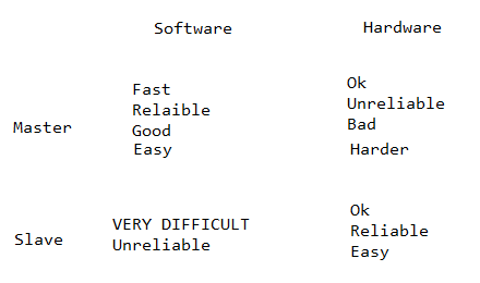
Initially, I was sure the right way to do it would be to have the hardware i2c stack drive the display and the software stack to act as the i2c target for the badge. This appears to be exactly the wrong approach. Knowing far more about i2c than I do, Charles Lohr offered this helpful chart:

In short, when at all possible you should use software for the master and hardware for the target (slave) device.
Fortunately, that meant I didn't need to do a lot of work. I could use the CH32V003Fun implementation of hardware i2c to interact as a target, and a software library to serve as the master to drive the display.
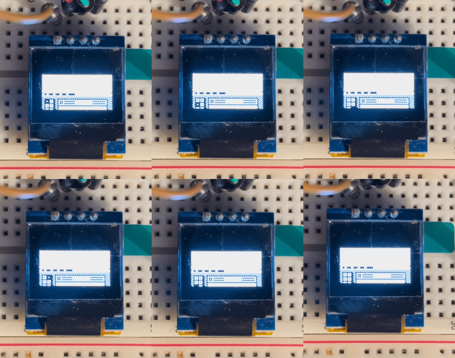
After a few days of hacking around with it I managed to draw data to the display, but it was offset by a couple of pages (8 vertical bits per page)

This was odd because the hardware i2c version of the code that I'd written didn't show this problem, and the display setup was identical. Eventually I found that the software setup I'd replicated was designed for displays that were either 64 or 32 pixels tall. Mine is 48, and I needed to adjust the screen multiplexor to wrap at the right width for the right number of lines.
The rest of the weekend I hacked together a proof of concept for running both i2c channels and it's working!

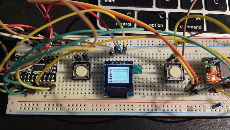
This version is the display running off the CH32v003 on the left (Software I2C) and a Teensy 3.2 (on the right) is sending a packet (CHV32003 Hardware I2C as Target) to draw which tool is highlighted in this MacPaint window. It's an early test, but the proof of concept works. I have already rerouted the signals on the board.
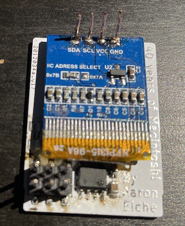
Lastly, the displays arrived. To my chagrin, they already have headers in them. This means that I'll need to desolder the existing headers and setup new ones. Because of my preference for a surface-mount connection, I also have to add my own headers to the board.
I bought some AWG24 copper jeweler wire at a local craft store. Then I make a little bed, and hand solder. I haven't come up with a better process yet...

Next steps:
- Make sure Button interrupt works
- Protocol for sending commands
- New PCB spin
 Aaron
Aaron
Discussions
Become a Hackaday.io Member
Create an account to leave a comment. Already have an account? Log In.