-
PCBs and first assembly
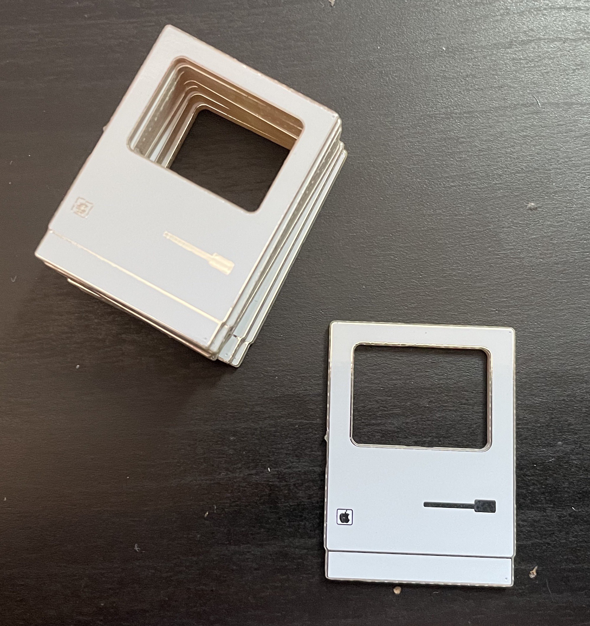
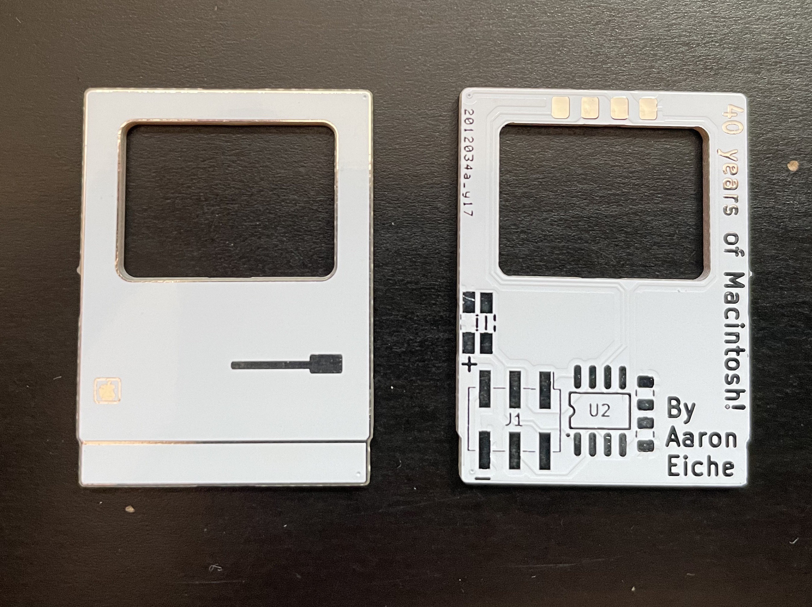
08/16/2024 at 06:00 • 2 commentsMy first PCBs arrived yesterday and I'm really pleased with how they turned out! I was feeling a bit concerned about the detail of the apple logo, and and the outline around the shape that was provided by masking, but I don't think I could be happier with how it looks. It's really great.
![]()
![]()
I soldered one together and immediately ran into a problem. I couldn't get the programmer to talk to the chip. I checked the connections, checked the pinouts, checked continuity. I tried unplugging it and got the same response. The programmer didn't think there was a chip present - but the programmer reported that it was "already connected" and also reported the wrong chip.
I did a visual inspect of the header, and it looked like it really wasn't very well soldered onto the board. While I plan on reflow-soldering most of these, this first one I thought could just be hand-soldered. I added some more solder to the SWD pin (the 1-wire programming pin) and like magic, it worked!
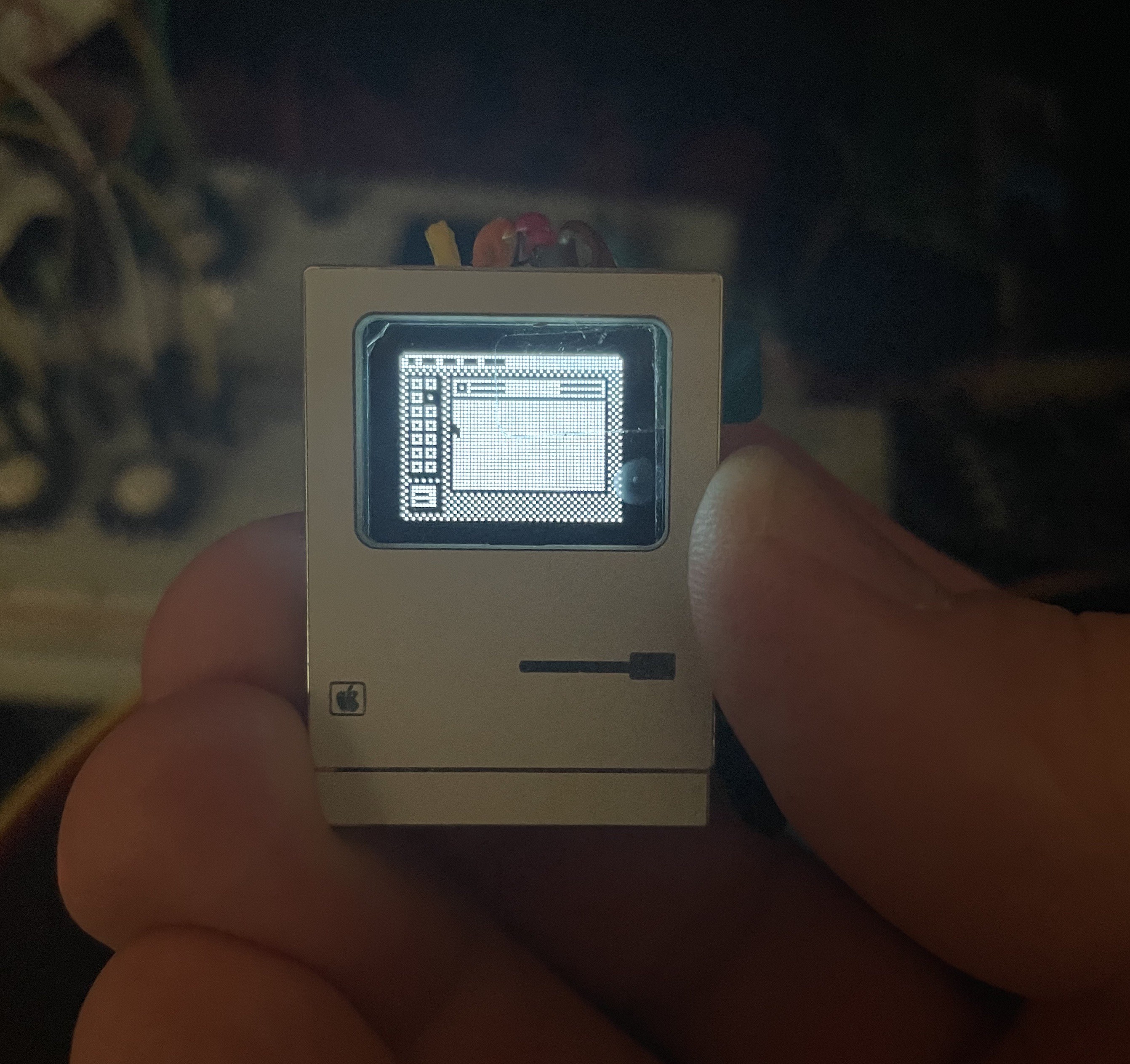
For lack of a better-solution, I soldered some stranded wire to the display headers. I mentioned previously that I made these surface-mount because I wanted to keep the aesthetic of the front of the board - there wasn't room for single-row SMD header pins. My current plan is to use 20 gauge bare copper wire (like jewelers use) to go from the board to the display. I thought about just buying some solid-core wire, but it would require an awful lot of wire stripping on some very short wires.
In the meantime, here is the assembled v0.5:
![]()
Next steps:
- Try the bare-wire screen connect
- Order the OLED displays
- Order new PCBs with the fixed header
- Finish the software (I have a lot of display stuff done, but the interactivity would be nice)
If I time this right, I think I could get them all built pretty quick. It'd be nice to not have this come down to the wire.
-
Whoops! And other things...
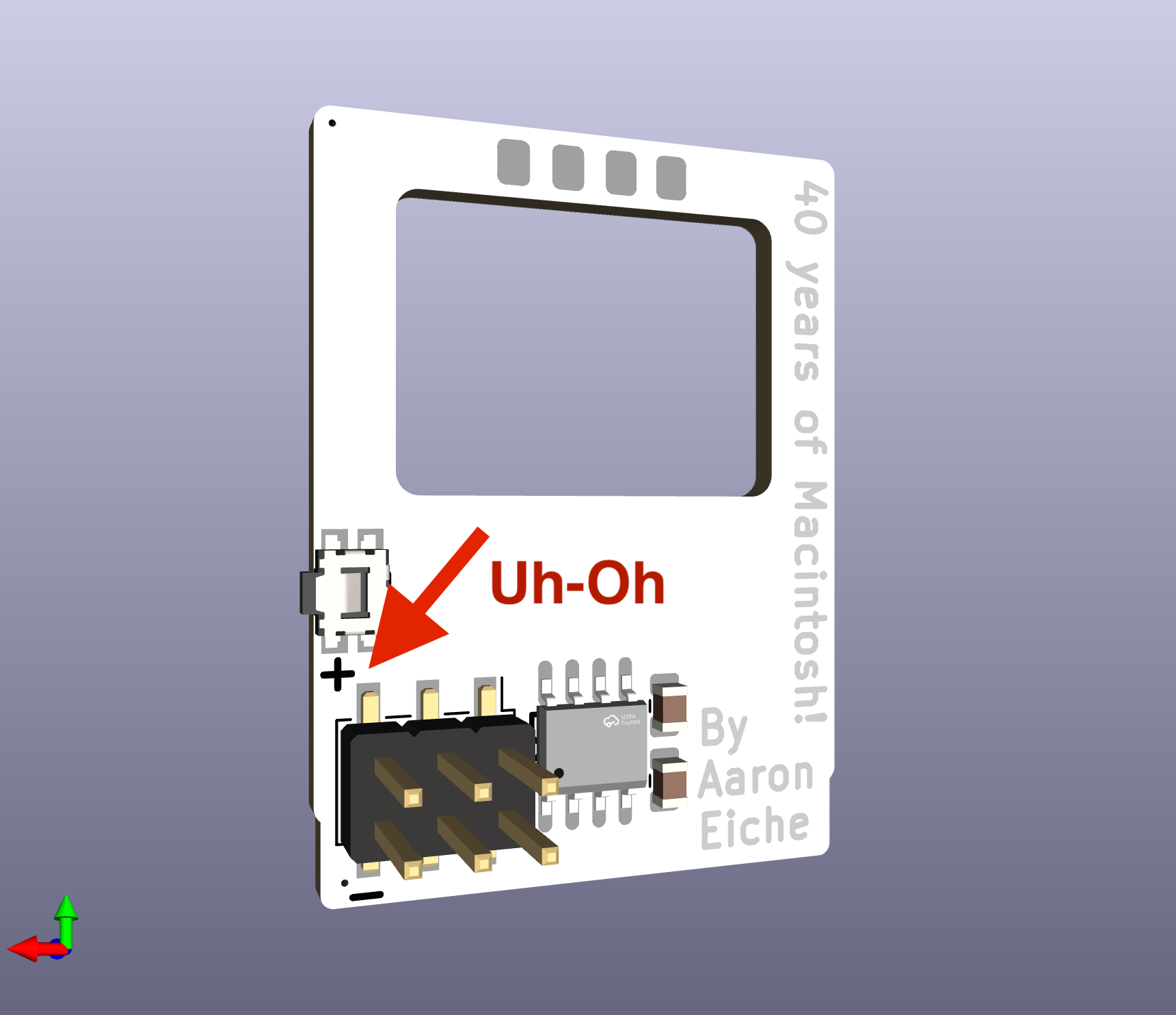
08/07/2024 at 23:18 • 0 commentsI am impatiently waiting the arrival of the components and PCBs that I ordered just a few days ago. While looking back at the last log I wrote, something caught my eye:
![]()
I put silkcreen + and - symbols near the header. And looking at the badge on my desk (shoutout to the Supercon 7 Vectorscope) I realized the position of the pins was wrong. I had the header backwards! Furthermore, I knew how I'd made my mistake:
![]()
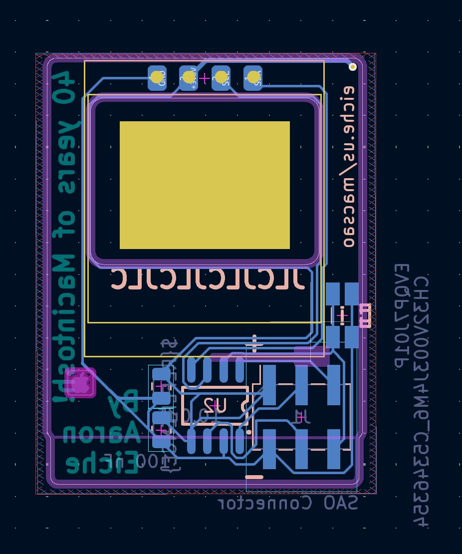
This is the view of my board from the front (after I corrected it.) Because the front of my board has no components on it I spent most of the time laying stuff out on the back. I think I even did it from the front and wasn't paying attention to the footprint orientation. Whoops! This could have been avoided if I'd used the "official" SAO footprint, but I didn't want the through-hole, so I made my own (I should know better by now.) As I said previously, I have made many PCB mistakes. This one is not huge. When the boards come, I'll still be able to program and test how everything comes together. And see how it looks visually. It just won't work plugged into a header. I'll respin, and try again.
Since my last project log here, Hackaday officially put Supercon 8 tickets up for sale. In that announcement we learned that this year's badge is going to focus on SAOs! There were some subtle hints about utilizing the whole 6-pin header. As I mentioned previously I included support for the Pins as a target device. However the CH32V003 only has one hardware I2C port and I'm using that for the display.
If I want to support I2C as a target I can either write a software I2C Driver (just bit-banging the protocol) or I could switch to another chip. The step-up from the CH32V003, the CH32V203 has two sets of I2C pins, so I could just switch chips and get that.
A third option would be to swap out the I2C display for an SPI version,. The displays are the same, but the protocol is different. In this case, I'd need to move from the CH32V003J4M6 to a different package that has a few more pins.
At any rate, I have some choices to make - and my original boards probably aren't going to arrive for another week.
-
Parts and PCBs ordered
08/02/2024 at 05:54 • 2 commentsI pulled the trigger and ordered PCBs and parts - so far everything except the displays. I've made a number of PCBs in the past ~15 years since I got into the electronics. Frequently I have made some silly mistake that has necessitated my ordering a new variation of a board. Of course every time I do it I try to be extra meticulous so as to not repeat the problem. As an abundance of caution, I ordered just 10 PCBs.
![]()
Interestingly in KiCad's 3D renderer the silver details
aren't visible looking at the board head-onI decided to implement a button (again, inspired by Tom Nardi's Cyberdeck SAO) for stand-alone interaction. Initially I was going to try to do this as a capacitive touch pad, but I've had mixed success with those in the past and space was already tight. This button is connected to the GPIO2 pin on the header so it could be triggered from whatever its attached to. The SAO header also implements a pair of i2C pins. I like the idea of there being an API to draw on the screen, but that necessitates writing an i2C software stack to handle the second i2c.
![]()
Now I just have to wait for all the parts to get here. I'm not in a rush, and it's still a few months until SuperCon, so its going to be a couple of weeks. After I've successfully assembled a board, I can order the remainder of PCBs and all the displays. -
Test Fit PCB
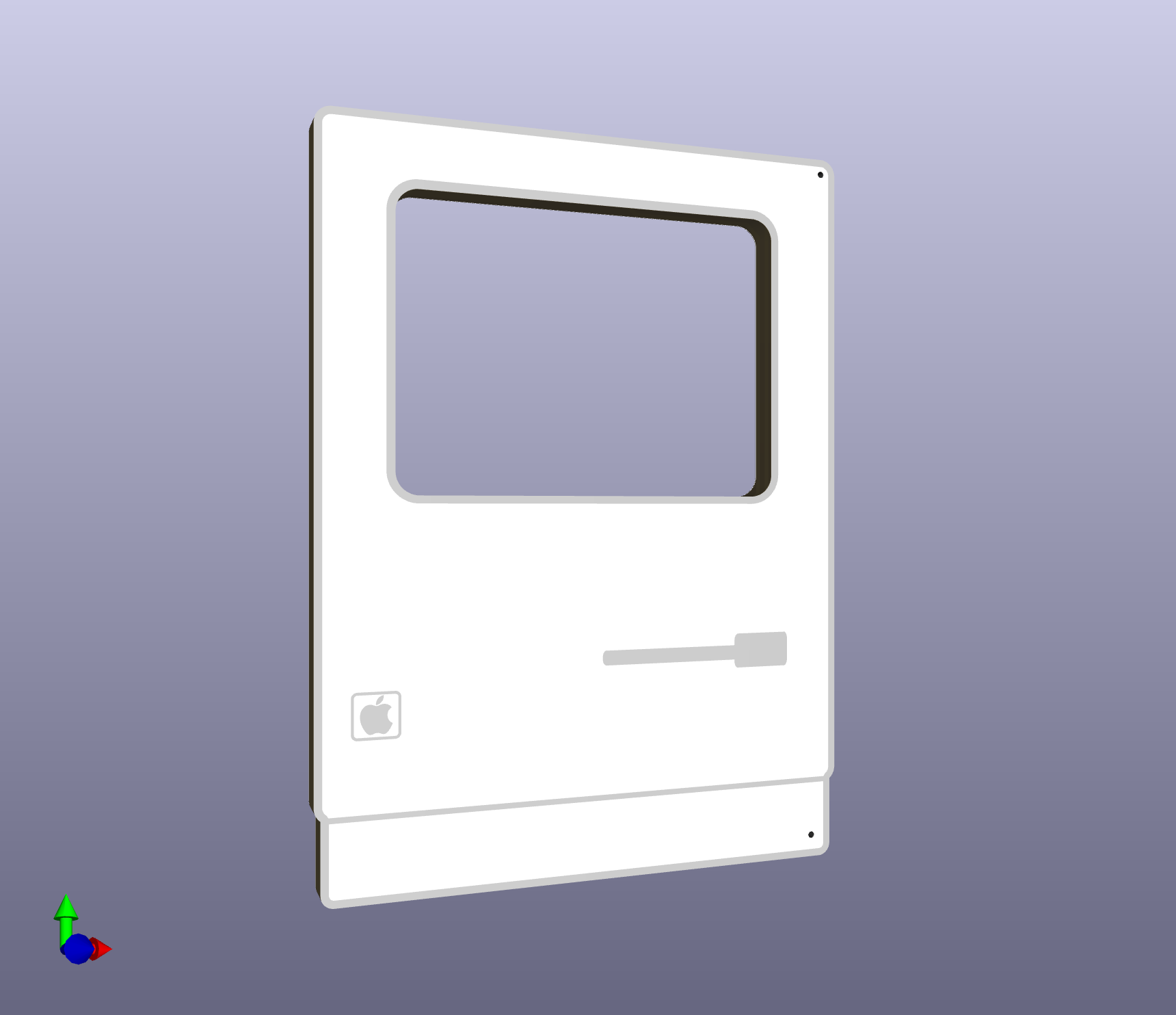
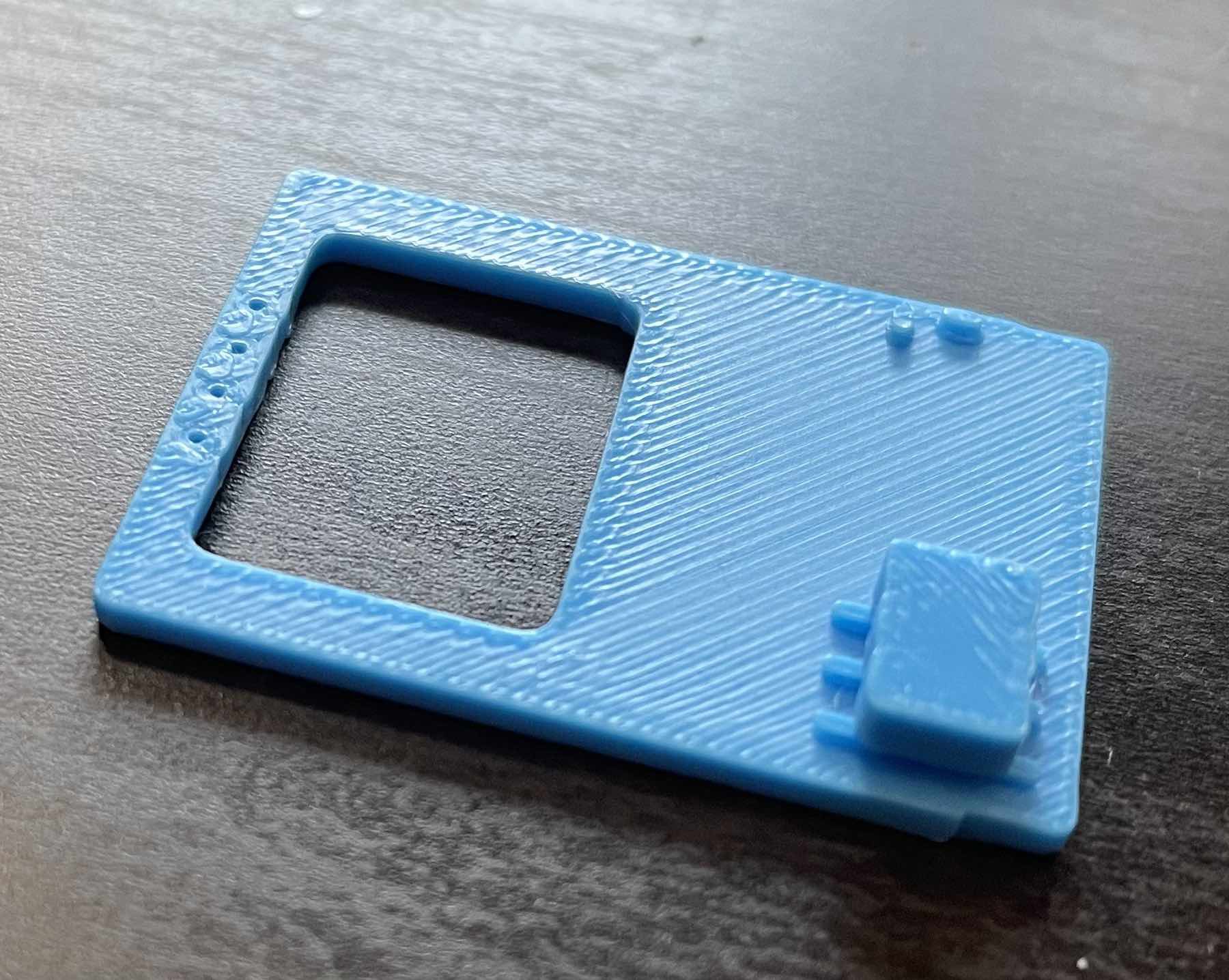
07/27/2024 at 07:01 • 0 commentsI've been working on the PCB recently and finally got a version working that I'm happy with (I think). Because I'm impatient, and want to avoid spending money where I can, I exported the generated STEP file from KiCAD and 3D Printed the board. I mostly did this so I could get a sense of size and check for component collision.
![]()
This printed version I clipped the header pins. It would be asking my printer for a lot to print those, and I didn't need to. I just wanted the bulk of it to get a sense of spacing. Also visible here are a couple of 0603 capacitors. One of the benefits of printing this is being able to actually look at the components. It's made me switch out the 0603s for larger 0805s. I'm not tight on space as I was when I was trying to make attach the display directly.
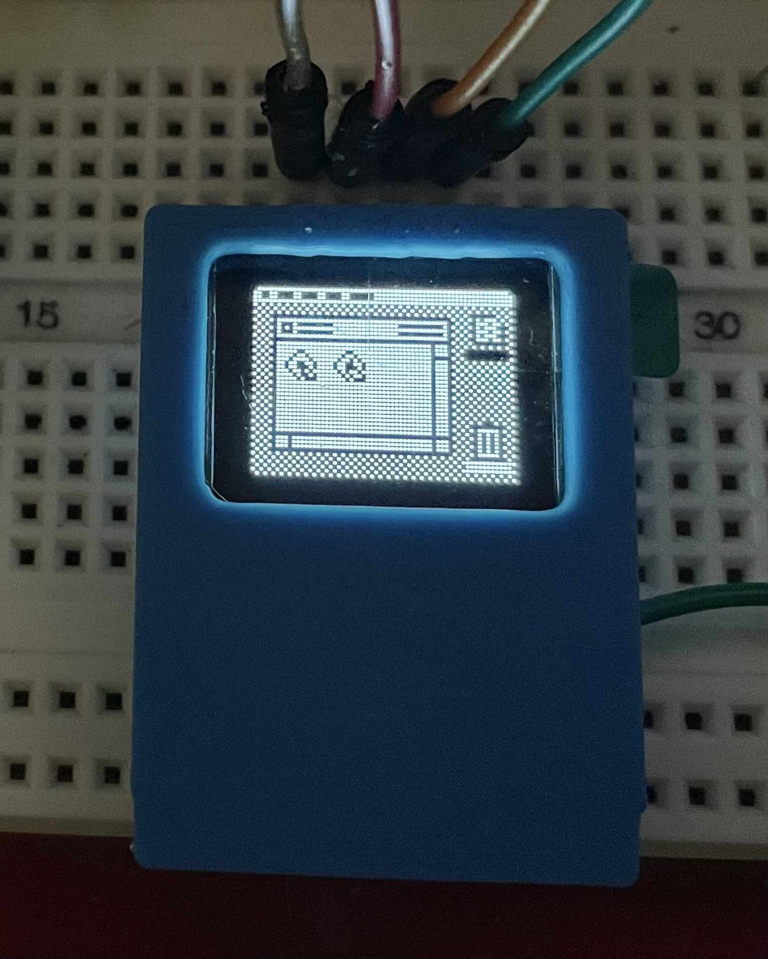
The main purpose is to see how the display fits:
![]()
Not bad! It's hard to see in this photo, but the display actually pops up a little at the top. I've decided to get the PCB manufacture, assemble and program one before I decide if it's worth trying to avoid. I have to remind myself to relax. This is just an SAO. I'm not building the Flux Capacitor, or the next iPhone. It's just a fun thing that (I hope) makes people smile a little.
-
Screens and sizes
07/16/2024 at 04:38 • 0 commentsI mentioned in a previous log that one of the things that kicked this off for me was the availability of an OLED display that was the right aspect ratio. This display is also quite small, and given the amount of space I have to keep everything to scale, I don't have much room to put other components.
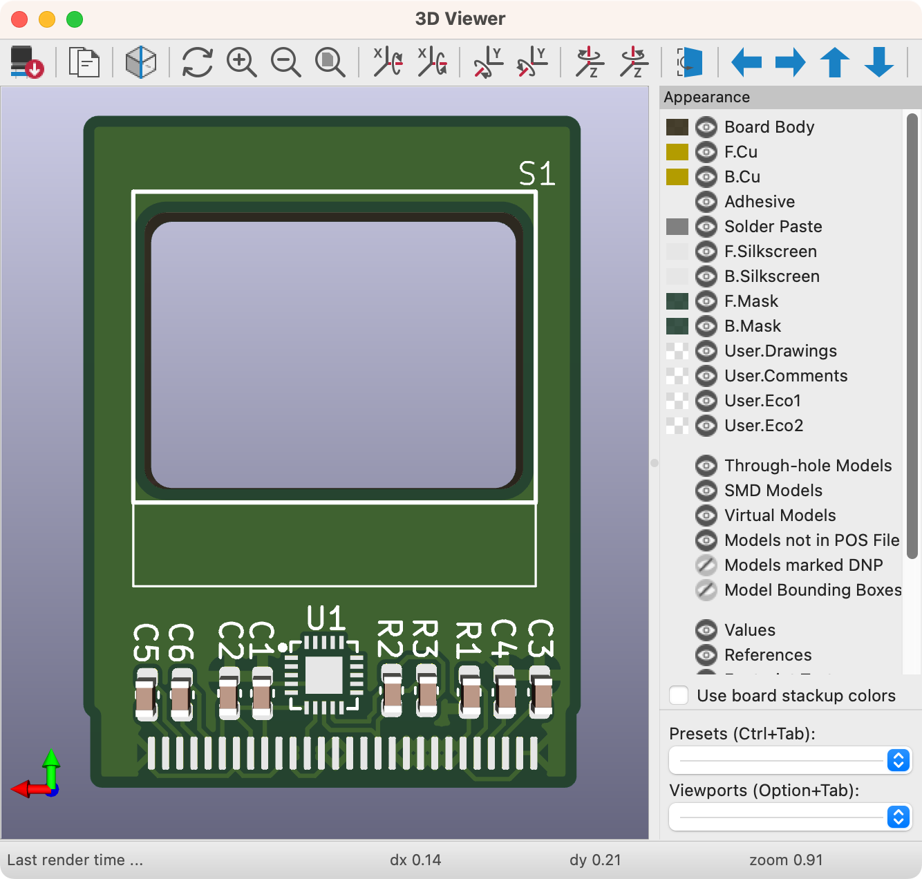
![]()
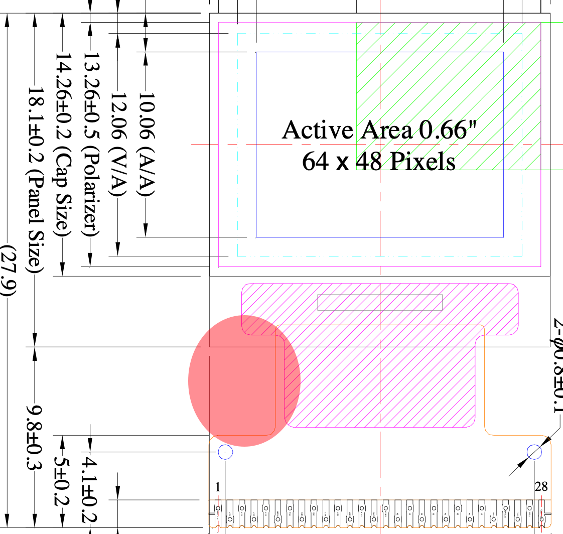
This render of my current version of the board shows the display outline where it would sit on the board. my current plan is to fix it in place with some hot glue. The trick is in connecting the ribbon cable. According to the datasheet, it's 9.8mm from the bottom of the display (the shorter rectangle at the bottom of the cutout) to the end of the ribbon, with a 1.5mm long solderable contact. In most situations, you would fold this under the display or around the back of a PCB where all the support circuitry is.
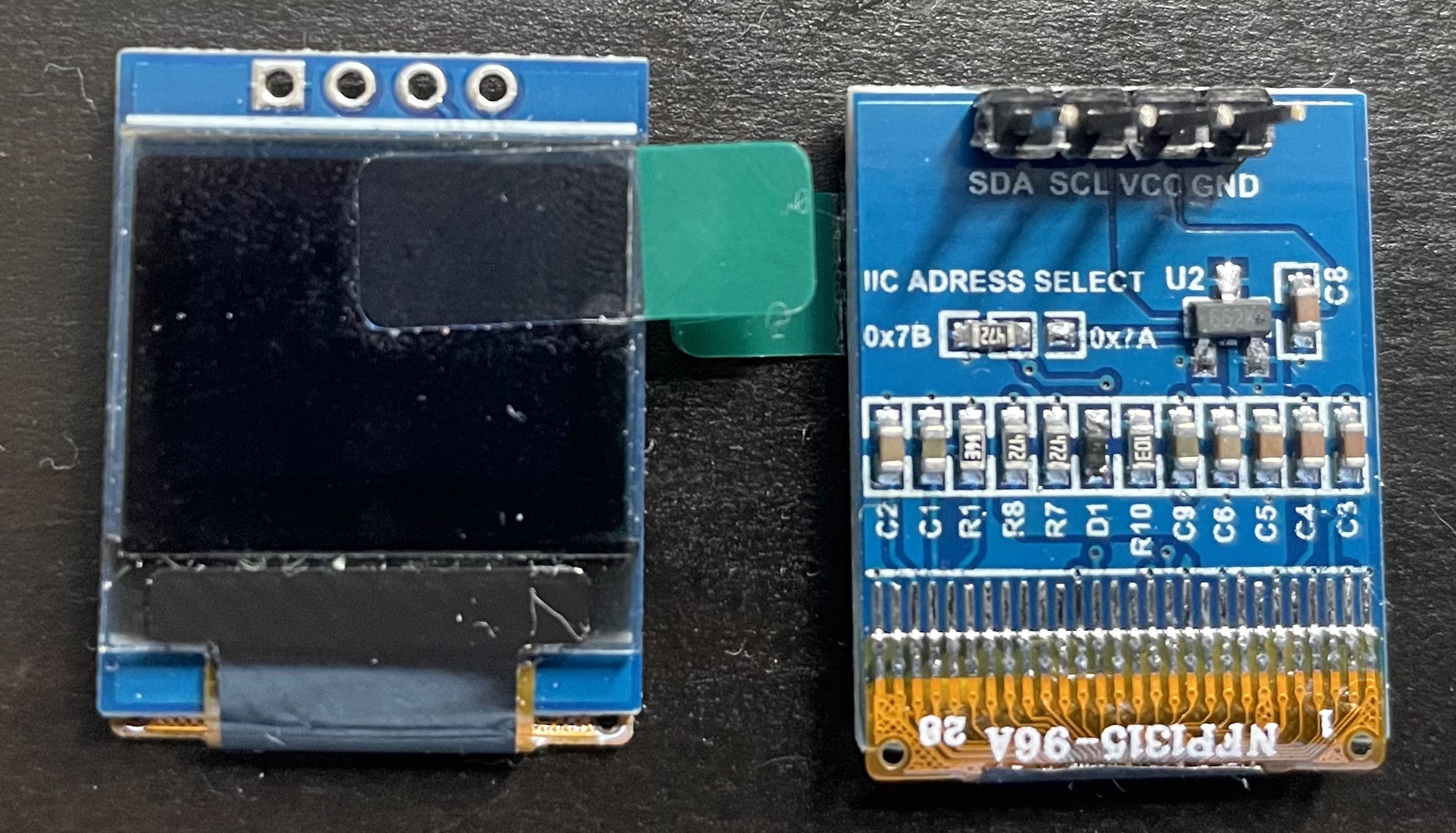
![]()
Front and back of a display module I could make a second PCB as a sort-of "backpack" for my board. In fact, I may need to do something like that anyway. One thing I'm missing from my current version is a means of actually plugging in my SAO to an SAO Header. An SAO without the header is just a weird PCB. I could probably rearrange some of the components but the ribbon cable is getting in the way.
One solution would be to try to utilize the cutout that exists in the ribbon as it makes a sort-of "I-beam" shape. The space provided here is very narrow: Just 4mm. If you known= your common unit conversions for electronics, you'll know that the 4-pin header for the SAO needs at least 2.54mm (0.1 inches) between pins. It's a tight fit. Additionally, because I'm trying to squeeze some components under there I'm thinking about flexing the ribbon cable a bit, which means that that space will be even narrower.
![]()
A possible position of the SAO header I'm inclined to think that the backpack idea is better than trying to shove everything onto a single board, but it also feels like that maybe goes against the spirit of the SAO.
SAOs were the result of manufacturing costs getting so low that you could make an electronics art project for the cost of a cup of fancy coffee. Now that chips, PCBs and components are all shockingly inexpensive, are we entering the era of the FAO? The Fancy Add-On? -
Now working on the little controller
07/05/2024 at 01:37 • 0 commentsFor a bit over the last few days I've been seriously concerned that I wouldn't be able to get this working on the CH32V003. I did a little bit of work myself - and started to poke around in different 003 firmware examples, and deep in the 1306 controller datasheet.
I was pursuing using the firmware from the CH32V003 Game console project by Stefan Wagner. Unfortunately I couldn't figure out the magic incantation to build successfully on an Apple Silicon host. I moved onto Charles Lohr's CH32V003Fun which has been highlighted on Hackaday a little while back.
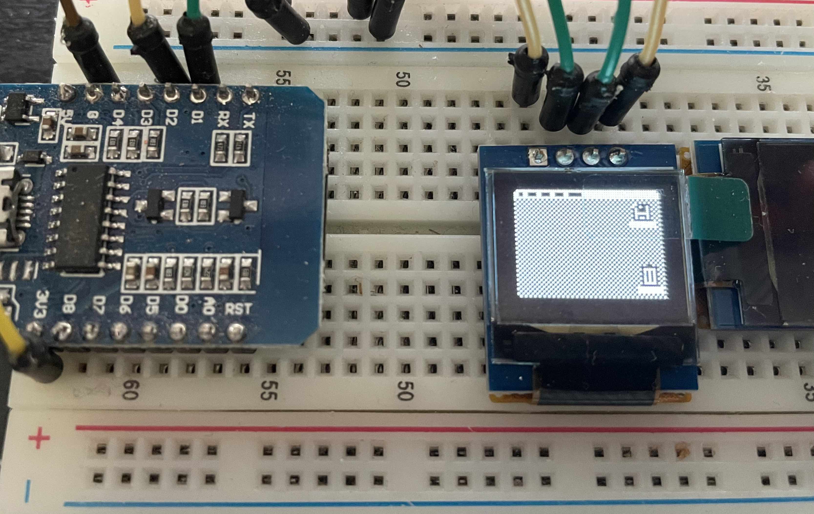
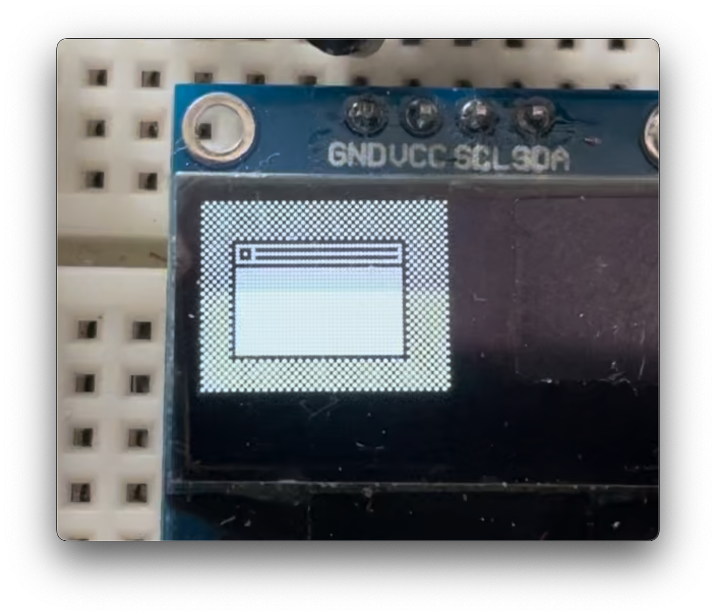
After having figured out offsets for the column and row in the display ram, I was able to get things on the screen! I've spent the last couple of hours porting my display commands from the u8g2 library running on an ESP8266 to the CG32V003Fun's built-in drawing commands. So far, my code size is about 1/3rd of what it was using the libraries. I still have quite a bit to go, but it's looking very promising.
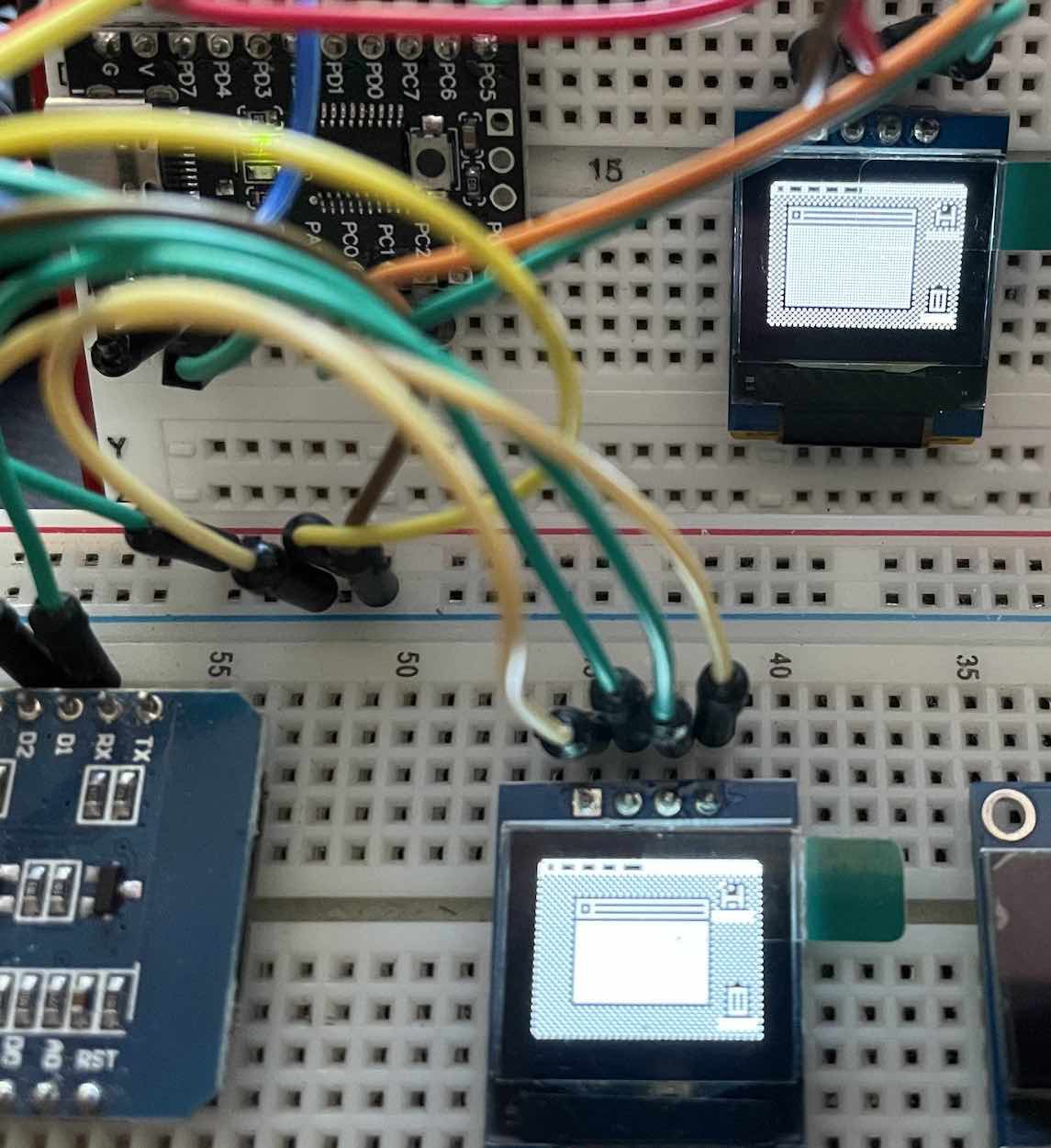
![]()
The ESP8266 on the bottom, The CH32V003 on top. -
"I finally invent something that works!"
06/27/2024 at 22:42 • 0 commentsThere are moments in every project where you wonder if what you're doing is going to work at all. I think this is especially true when you have several layers of uncertainty.
I got the programmer and compiler to work, so I knew I could program the CH32V003 to do something simple (blink an LED). I didn't know the following with certainty:
- If I had the OLED display hooked up correctly
- If I had the command startup sequence correct
- If I had transposed the custom commands from an example into Arduino's Wire library correctly.
- I was pretty sure the OLED display I had worked.
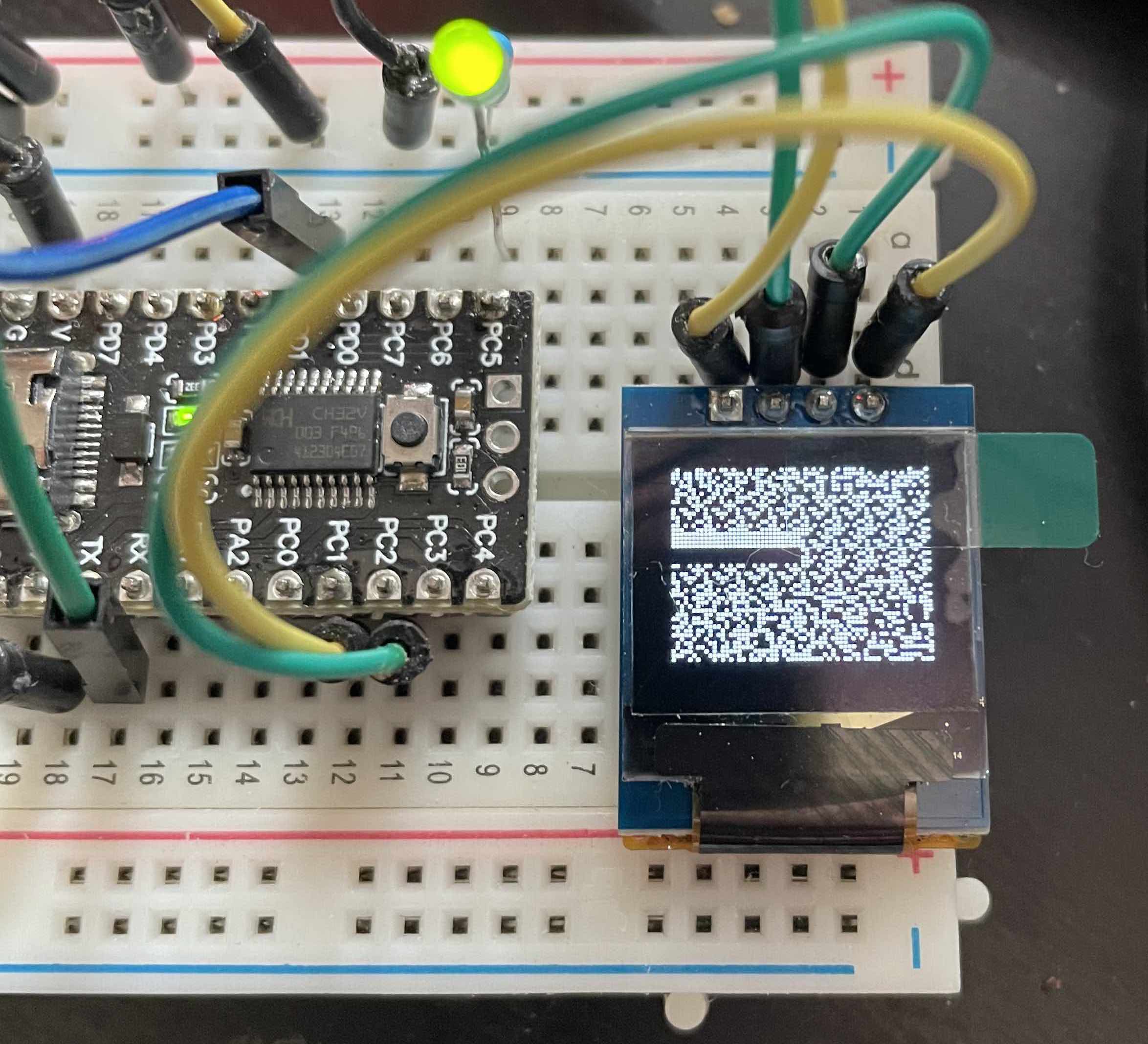
After messing around with a handful of various items, the display lit up full of random data... I assume it was whatever was hanging out in memory, or something like that. I also got, at one point a pattern... of randomness.
But after a few more pokes and attempts, I ended up with this:
![]()
It doesn't look like much, but those white and black bars were intentional - and that makes all the difference in the world. It's a good feeling when you see the fruit of your labor. You understand Doc Brown's surprised assertion when he sees the Flux Capacitor "It works! I finally invent something that works!"
Onto actually drawing something on the screen (and keeping it all in 16K)
-
A couple of hiccups
06/23/2024 at 22:54 • 0 commentsI've run into two hiccups in the last few weeks that are making me adjust course a little bit:
1) I had to switch graphics libraries. The Adafruit GFX and SSD1306 libraries are really only built for the displays that Adafruit sells. This is entirely reasonable, but my target display was a different aspect ratio - 64x48 - instead of the 128x64 or 128x32 displays that they offer. I could draw to the screen, but the output wasn't right. So I moved to the very accommodating G8U2 library. This library supports displays of every stripe. It is really impressive. I got all my various "screens" that I wanted to draw rebuilt in that library.
![]()
2) As I mentioned in my last log, I needed a programmer for the CH32V003. The programmer (A WCH-Link E) arrived
This is where the new challenges show up:
I've been developing on an ESP8266 WEMOS module. It was a quick and easy solution to get to an MVP. Unfortunately I wasn't paying attention and the CH32V003 doesn't remotely have the kind of Flash storage that the module does.
The Module's is 1MB. The CH32V003 has a paltry 16KB. This is plenty in relative terms, but it does make using the library a more complex task. It seems like it is compiling unnecessary features into the file. I may just bail on it and implement my own drawing routines.
Also, due to Apple's aggressive code signing policy I haven't been able to program the chip from my Apple Silicon Mac (it doesn't like that the libusb that the programmer needs isn't signed for that use by the appropriate team). Fortunately My old intel Mac is okay with it all, so I am able to program from there.
-
I guess I need a programmer
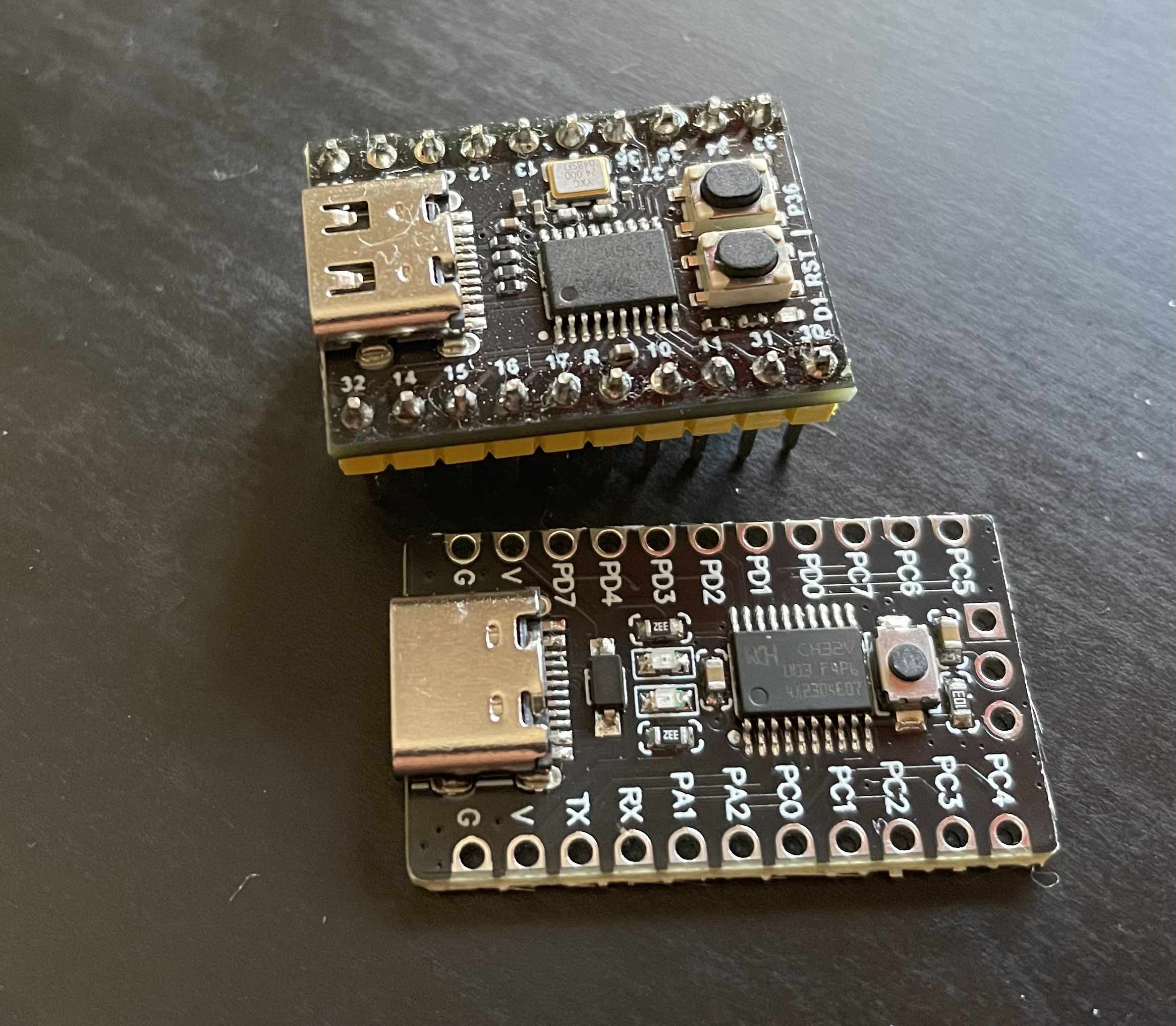
06/06/2024 at 01:21 • 0 commentsI bought handful of CH32V003 boards to play around with running this project off of. My development setup is currently using an Espressif ESP8266, and I was leaning towards the CH552 until I discovered the CH32 line. The latter is very cheap, RISC-V, and has an officially supported Arduino build environment.
![]()
CH552 above, CH32V003 below What these boards don't have is a bootloader. I assumed because the 552 shipped with a bootloader that the 003s would have one as well. Whoops. Short of ordering the appropriate WCH WLink E programmer, there is one potential solution. Charles Lohr did the tough footwork of putting together a build chain for the CH32003 (https://github.com/cnlohr/ch32v003fun) and in that, there's a firmware option built on an Arduino Uno that might be enough to load a bootloader. I guess we'll find out.
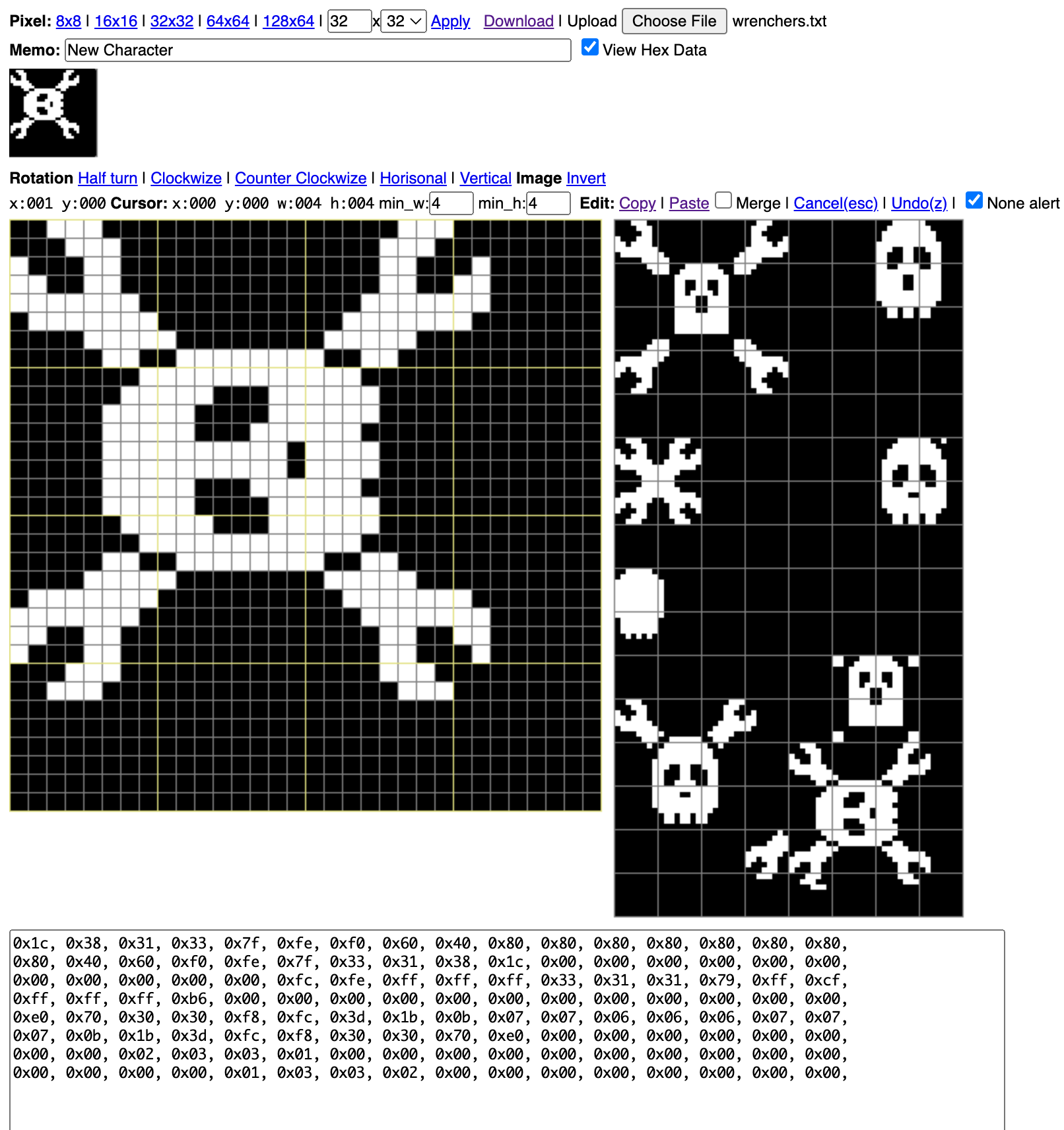
One of the things that I wanted to do on the display, was draw a little Jolly Wrencher. I'm planning on taking this Supercon '24, and it's a nice callout as I can draw to the display. So I've been experimenting with drawing Jolly Wrenchers
![]()
These were made using the excellent bitmap editor from emutyworks. It takes some getting used to, but once you get the hang of it it's quite nice.
I think I've settled on a design, but I'm not sure about the wrench lengths. I need to check how much space I actually have to populate.
-
Why not share?
06/03/2024 at 17:47 • 0 commentsSupercon 2023 was my first supercon, and it was quite a lot of fun. Like many people I was delighted by the weird variety of SAOs†. I was especially inspired by Tom Nardi's Cyberdeck SAO. The integration of the OLED display made it super fun. I wanted to make my own.
2024 happens to be the 40th anniversary of the original Macintosh. If you're an 80s child like me, take a moment to stare off into the distance with a look of shock. Back to the project! With that milestone in mind, I thought I would make an SAO that looked like an original Mac and I could put an OLED screen on it and display some fun stuff.
This idea has been bolstered by two hardware finds:
- A 0.66" OLED 64x48px display.
- The unfathomably cheap WCH CH32V003 microcontroller
The display is the same aspect ratio as the original make (1/8th the resolution) and uses the commonly available SSD1306 driver. The microcontroller is $0.30/pc, runs at 48Mhz, and has an accessible Arduino ecosystem available to it. This makes it super easy to get started.
Additionally, both JLCPCB and PCBWay now offer full color printing on their PCB production. I haven't committed to it yet, but if I wanted to really match the beige color of the original Mac, I could do it.
While I await some development boards for the MCU, I'm developing some drawing methods. I have to adapter the common elements to the resolution of the display, so I can't quite make it a Mac, but I hope to evoke the feeling of the original Mac.
The showman in me is always trying to keep things a secret, and let it all be for the big reveal. In the spirit of open-source and open-ness, I'm publishing the project here, and hopefully as-I-build-it.
![]()
† I prefer to say shoddy-add-on, but acknowledge what the commonly accepted acronym is.
Macintosh SAO
It's the 40th anniversary of the original Macintosh. Why not recapture the magic in an SAO?
 Aaron
Aaron