 eric
ericSo since I last checked in with you guys not a whole lot has changed. I took the power regulation subsystem and created a pcb layout for it, which you can see below;
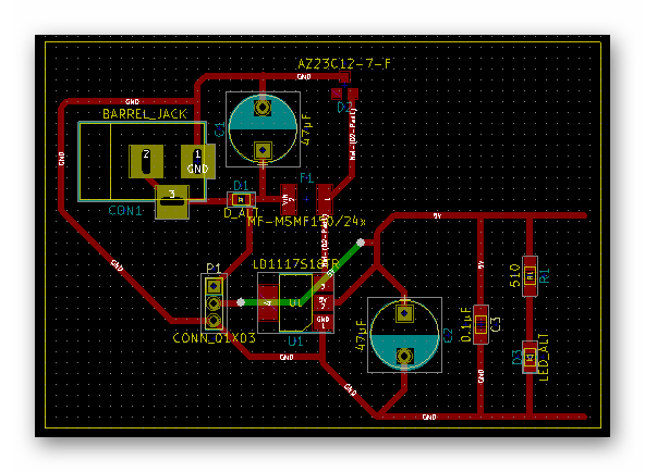
I have yet to mill a board using this layout, I'll be doing that on Monday. Hopefully I'll receive the parts for this board soon so that I can use this board for its intended purpose, to test the capabilities of this subsystem. This subsystem is particularly important as we wanted to make the board far more rugged, simply because this product is made for kids and first time hobbyists. We don't want a mistake such as shorting 5V to ground or putting a large voltage into Vin to cause the board to break. There are more circuit protection elements that have been introduced into the schematic in other subsystems as well. Included in this layout is a zener diode and a resettable fuse that are responsible for opening the circuit if the circuit is powered by more than 12V.
Aside from that I am continuing to layout other subsystems and sooner or later will start integrating them together.
Till next time,
-Eric
Discussions
Become a Hackaday.io Member
Create an account to leave a comment. Already have an account? Log In.
Looks good. You might want to look at the barrel plug again thought. It looks like you have ground connected to the center of the plug (1), but the center is almost always positive.
Are you sure? yes | no