Close
0%
0%

Smart EE designer Business Card

My personal business card

Similar projects worth following
I plan on creating such personal business card since some time ago. Some of my HW designer coworkers already designed and built their own and this motivated me too. The hackaday 2024 Business Card Contest also motivated me to get this project started as soon as possible.


This product aims to have the following features and design prerequisites:

- Ultra low power MCU use. I plan on using MSP430G2553. 

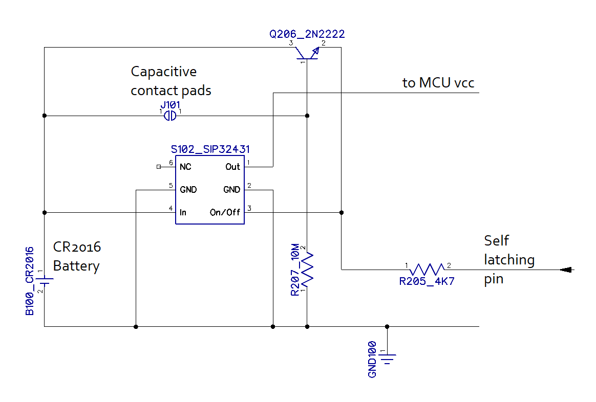
- Custom made self latching circuit for ultra low standby power consumption (in the realm of 1nA).

- Coin cell powered. CR2016 battery choice because it has exactly the same thickness as the pcb itself. I plan to insert it in a cutout hole so it wouldn't stick out. Both faces of the battery should be at the same level with the faces of the card.

- 10 years battery lifetime in standby. 

- No mechanical switches. The ON/OFF switches should be replaced with capacitive touch pads Mechanical dome switches stick out too much and make the card way too thick. 

- OLED display. The 0.96'' display should also be inserted in a PCB cutout that is 0.5mm larger than the outer edges of the board of the display. This way, the actual face of the display can be at the same level with the top surface of the card's PCB. 

- Regular Fr4 PCB thickness of 1.6mm ( I have to decide upon the color) 

- Credit card size with rounded corners (85x55mm).

- The SMD components will only be populated on one of the sides so I can obtain a lower overall thickness in the end. Sot23, 0603 and 0805 component sizes will be used due to low thickness values. The maximum overall thickness of the business card should be the thickness of the PCB + the thickness of the sot23 components. 

- Components should be kept populated towards the middle of the board and not around the edges. This provides lower overall thickness of the card around the edges and allows it to better fit in most wallets. Also, populating the components towards the middle, reduces the risk of them breaking off the board. 

- Once turned on, the card should display a rolling message composed of full name, occupation, phone number and business email address. (Maybe the logo of the company too)

- After the contact details, it should display a brief end screen with the SW version and the battery voltage for traceability. Then the circuitry should enter deep sleep. 

- Written on the silk layer of the PCB: Top - full name, Bottom - QR code with the hackaday profile web page. 

--- Firmware will be added soon. ---

Smart EE Business Card_C1.dip

Layout. To be opened with DipTrace.

dip - 465.11 kB - 06/25/2024 at 16:40

Download

Smart EE Business Card_C1.dch

Schematic. To be opened with DipTrace.

dch - 363.92 kB - 06/25/2024 at 16:40

Download

  • How the Self Latching circuit works?

    Marius Taciuc06/25/2024 at 17:33 0 comments


    The circuit uses an amplifier BJT transistor for the contact pads. When these pads (J101) are being touched, there is a leakage current of a few microamps flowing through the resistance of the skin of the finger towards the base of the Q206. This small current is enough to make the BJT conduct enough to turn on the S102 static switch. When the SIP32431 switch turns on, it provides full power to the MCU, display and all the other circuits on the PCB. Once the MCU is being powered, among the first things that it does, is making the Self latching pin High. 

    This first step of priming the current flow happens very fast in less than 4ms. After this step, the user can remove the finger from the pads and the circuit will self sustain through the intervention of the MCU. 

    After the MCU runs the entire code and scrolls the text, it makes the Self latching pin Low. This turns the entire circuit off.

    The cycle repeats each time someone presses the contact pads. 

    Why is the standby current so small (less than 1nA)?

    During the standby, the Q206 BJT is blocked and the SIP32431 is turned off. The only ways for the current to flow would be through the C-B junction of the Q206 (which is reverse polarized), and through the blocked P channel of the internal MOSFET of the static switch. These two blocked semiconductors do have impurities and they do have leakage currents, but these currents are usually the order of 0.00000001 A or less. 

  • Testing the circuit

    Marius Taciuc06/25/2024 at 16:29 0 comments

    I tested the self latching circuit using a scrapped PCB from an old project of mine. This PCB was already having the proper pads for the TSSOP microcontroller. 

    I powered the circuit exclusively from the coin battery in order to be able to check if that can provide enough power. I also did a leakage current test with a bench Keysight 34461 multimeter. The measured stand-by current was less than 1nA. The current absorbed by the circuit in normal functionality, varied between 5mA and 8mA, depending on the image on the screen. According to the datasheet, the capacity of the battery is around 70mAh and this means that it could power the circuit for an average of around 10h. If the scrolling message lasts around 12s, this can result in being able to display the message roughly 3000 times before the battery drains out.

    I am really happy with this test. This means that I can now order the PCB from the supplier. 

View all 2 project logs

Enjoy this project?

Share

Discussions

Similar Projects

Does this project spark your interest?

Become a member to follow this project and never miss any updates