The CanHobby ATTiny10-Solo is a minimal development board for the ATtiny10 MCU from MicroChip. It is designed to be used on a breadboard and has no on-board LED.
Everyone knows how to write a simple Arduino sketch but the ATTiny10 is a little different. Due to it's limited SRAM and Flash memory, conventions such as digitalWrite() do not exist. This sketch will illustrate the use of "Register Programming" which is at a lower level, just one step above assembler.
The source code and required Boards Package used in this example are listed in the Instructions.
I plan to include several different sketches highlighting different peripherals featured by the ATtiny10 MCU. The most important sketch presented here is a ATtiny DEBUG Display to make code development and debug easier. This becomes even more important when one keeps in mind the lack of a serial port on these Tiny MCUs.
"DEBUG display" details:
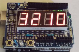
The DEBUG display uses an eight digit 7 segment LED display available from many sources including CanHobby and AliExpress. It has a pseudo SPI interface using a MAX7219 for which this sketch provides a simple bit-banged driver. Although it uses 3 pins to connect any interference with the operation of other modules that you may have connected can normally be compensated for in the sketch.

The display connections are as follows:
Vcc --> +3.3V or +5V
Gnd --> 0V
MAX7219_DIN --> B0
MAX7219_CS --> B1
MAX7219_CLK --> B2
The simple bit-banged driver provides 5 methods:
- Seg7_hex( uint8_t hex_number, uint8_t position ) - where "hex_number" is the 0x00-0xFF hex number to display, and position is the starting LED position to display the 2 digit hex number. Position 0 starts from the left.
- Seg7_dec2( uint8_t dec_num, uint8_t position ) - where "dec_number" is the 0-99 decimal number to
display, and position is the starting LED position to display the 2 digit decimal number. Position 0 starts from the left. - Seg7_clear( uint8_t position ) - is used to clear the display starting from the indicated position.
- Seg7_dec( uint16_t dec_num, uint8_t position ) to display a 4 digit decimal number exists but has not been tested.
- Seg7_init() initializes the 7 segment display.
Sketch Overview:
The ADC_7Seg.ino sketch serves 2 functions.
- Using the Debug Display.
- Using the ADC (analog to digital converter) on the RESET pin.
It is very simple - in setup() we initialize the ADC on pin B3 and then initialize the Seg7 debug display and clear it. In the loop() we read the ADC value and display it on the debug display, wait 2 seconds, and repeat.
Setup Code:
#include <util delay.h>    // this is for the delay_ms() function.
#include "Seg7.h"          // this is my Seg7 driver.

#define ADC3  3            // we will be using ADC # 3 which is on B3

void setup() {

  ADMUX  |= ADC3;            // we will use ADC3
  ADCSRA  = 1<<ADEN | 3<<ADPS0;  // Enable ADC, 125kHz clock

  Seg7_init();   //  this will set B0, B1, B2 to OUTPUT for both the Seg7 and the 74HC595

  DIDR0 = 0x08;  //  Disable GPIO functions on B3 - RST/ADC3

  Seg7_clear( 0 );  // Clear the Seg7 display starting at position 0

}
Loop Code:
void loop() {

  ADCSRA = ADCSRA | 1<<ADSC;  // Start ADC
  while (ADCSRA & 1<<ADSC);   // Wait while conversion in progress
   _delay_ms( 4 );

 d = ( ADCL );  // get the ADC reading into a variable

 Seg7_hex( d, 1 );    // display the ADC value at position 1 of the debug.
_delay_ms( 2000 );

}
Grasp the thermistor between your fingers - you should see the reading go up.
This is a very simplified example but illustrated how to use the ADC and show the value on the debug...
Read more » CanHobby.ca

 SAYANTAN PAL
 sjm4306