See Edits below!
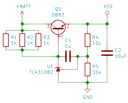
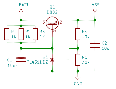
If a product claims have an input voltage range of 4.5V to 40V the internal power supply should be somewhat robust. The DC/DC converter discussed in the previous log entry uses the following as a linear regulator circuit for the 3.6V that I measured with my Fluke voltmeter:
I used hints from this write-up to do some simple calculations:
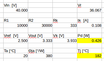 At 40V and a (hypothetical) ambient temperature of 20°C, the TL431 power dissipation is 30% above Absolute Maximum Ratings!
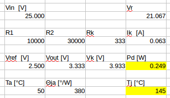 Since the temperature around the TL431 is bound to be closer to 50°C, an upper limit of 25V would be safer of the TL431 is to stay below the damaging junction temperature of 150°C.
On the other hand, if I calculate with 25mA operating current of the µC (including LED display) then the LM317 in a TO92 package used in other "DCDC converters w/ voltmeter" impose even lower limits to the supply voltage (19V×0,025A×160°/W + 50°C = 121°C, datasheet).
This means that the "DCDC-MH" module is a bit more sturdy than the other breeds.
Of course, this still doesn't explain why I measured 3.6V instead of the 3.33V that the application note makes me expect (maybe the "generic TL431" is rather "D" instead of "B" grade ;-) ).
The other thing that strikes me is the role of Cx. Doesn't amplify noise transmission from +BATT to +VSS?
The circuit discussed in the write-up mentioned above would be more like this:
Unfortunately I currently don't know how to simulate the transient response of the linear regulator. Maybe someone has a suggestion?
Edit 1:
1. After @Ken Yap pointed out a mistake in my circuit-reading, I corrected calculations and findings. Due to reciprocity of error and effect the results didn't change ;-)
2. Ken proposed that operation without LED current might be outside the operating range of the linear regulator circuit on the DCDC-MH board, and that it hence reaches 3.6V instead of the expected 3.33V. I tested that hypothesis and didn't find any load dependency:
- 3.64V without LED
- 3.64V with LED
- 3.64V LED + 10mA load
- 3.63V LED + 30mA load
- 3.63V LED + 40mA load
Also I killed the D882 (and had to replace it with an 40 year old BC238 from the used parts box but the voltage didn't change).
Note to self: there is a reason why the TL431 and 78L05 style linear regulators have protection circuits!
Edit 2:
@rubypanther thinks that the purpose of the cap in the DCDC-MH circuit is soft-start or reduced transient responses. He might have a point, and it might not be unusual at all: the TI TL431 datasheet proposes a very similar circuit:
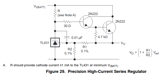 Stability and phase reserve of the TL431 seems to be an"interesting" problem for design engineers.
  Thomas
Discussions
Become a Hackaday.io Member
Create an account to leave a comment. Already have an account? Log In.
The cap is for some transient response tweaks - a bit like a PI controller. It is commonly used in flyback for optoisolator feedback. https://www.plexim.com/files/plecs_tl431.pdf
The math is a bit more than I would want to deal with.
HT75xx series of LDO (available on ali) is the few that I can think of for wide range. It goes up to 24V. I would use that and may be 78Lxx for higher voltages.
I usually use a constant current source with zeners when I need very wide input range (to 80V), but it doesn't work too well for the lower input in your case. The only crazy hack I can think of is PTC resistors thermally coupled to the TL431 that lowers the current when it gets warm. :P
Are you sure? yes | no
Hi K.C. thanks for your comment and for the outstanding source! The capacitor's role is in this circuit is thus similar to one in a OpAmp negative feedback loop.
With respect to the power supply range I guess that is room for supporting a wider input range by replacing the 333R (3x1k) with 2k. At at 6V with hFE = 100 it should still be possible to get Ice > 60mA. Ik (K-A current through the TL431) is then 1mA.
Are you sure? yes | no
Wait, the power dissipation in the TL431 is the voltage across it X the current. The voltage should be around 3.9V so that the D882 transistor has 3.3V at the emitter. The current, calculated from the voltage across R1-R3 is 12mA as you calculated, a little less due to the base current but we ignore that. So the dissipation should be 3.9V X 0.012A, which is 46.8mW, quite safe. Most of the dissipation is borne by the resistors.
Maybe the output voltage was 3.6V because the load (the STM8 and LEDs) didn't draw enough current to allow regulation. Did you measure 3.6V with the LEDs off?
Are you sure? yes | no
You're right, my mistake! It's the voltage accross R1-R3 that's (VBatt - 3.9V)! The lower dissipation of 12mA*3.9V is, of course, a lot lower!
Yes, 3.6V were measured without any LED current and with the STM8S003 still blank (thus idling at 2MHz). I'll devise a method of getting better measurements - the voltage stability matters, and to the (ab-)use of GPIO drivers as current limiters measurement can only be done when the LEDs are off.
Are you sure? yes | no
I did the math again and to my surprise the power dissipation didn't change since the current Ik is higher now (108mA at 40V). At 25V I get Ik = 63mA.
Are you sure? yes | no
@Ken Yap: see edits above - I guess I'll order some transistors (preferably SOT-89 package ;-) )
Are you sure? yes | no
BTW I bought some of the following SOT-89 from ali as I don't have any medium power parts >40V or >200mA.
BCX56 [80V][1A][NPN]
BCX53 [80V][1A][PNP]
They are selling the BCX56 -10 parts.
Are you sure? yes | no