Thomas
-
New boards have arrived
02/01/2020 at 13:36 • 1 commentI ordered some more boards from this shop: they look the same as the one I described in my previous log entries. Spare "D882" transistors and TL431 chips are also at hand.
Now I need to figure out how to decouple the feedback path from ground in a way that's easy to do and that doesn't look to kludgy. I ordered small diamond cutting discs which might be the right tool for this job. Let's see what works best.![]()
Edit: as of October 2020 boards are still available from the same shop above. If you're looking for alternative sources look for a blue board with a single push button, not two. -
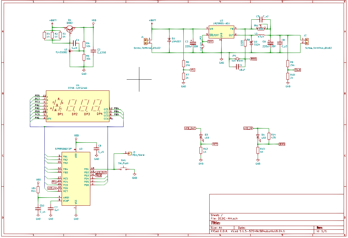
DCDC-MH circuit diagram
12/28/2019 at 12:25 • 2 commentsModding a module is easier with a circuit diagram. I made one (instead of knitting):
I'm going to refer to to this diagram when discussing modding options.
-
This linear regulator circuit doesn't look quite right
12/25/2019 at 10:55 • 7 commentsSee Edits below!
If a product claims have an input voltage range of 4.5V to 40V the internal power supply should be somewhat robust. The DC/DC converter discussed in the previous log entry uses the following as a linear regulator circuit for the 3.6V that I measured with my Fluke voltmeter:
I used hints from this write-up to do some simple calculations:
At 40V and a (hypothetical) ambient temperature of 20°C, the TL431 power dissipation is 30% above Absolute Maximum Ratings!
Since the temperature around the TL431 is bound to be closer to 50°C, an upper limit of 25V would be safer of the TL431 is to stay below the damaging junction temperature of 150°C.
On the other hand, if I calculate with 25mA operating current of the µC (including LED display) then the LM317 in a TO92 package used in other "DCDC converters w/ voltmeter" impose even lower limits to the supply voltage (19V×0,025A×160°/W + 50°C = 121°C, datasheet).
This means that the "DCDC-MH" module is a bit more sturdy than the other breeds.Of course, this still doesn't explain why I measured 3.6V instead of the 3.33V that the application note makes me expect (maybe the "generic TL431" is rather "D" instead of "B" grade ;-) ).
The other thing that strikes me is the role of Cx. Doesn't amplify noise transmission from +BATT to +VSS?
The circuit discussed in the write-up mentioned above would be more like this:
Unfortunately I currently don't know how to simulate the transient response of the linear regulator. Maybe someone has a suggestion?
Edit 1:
1. After @Ken Yap pointed out a mistake in my circuit-reading, I corrected calculations and findings. Due to reciprocity of error and effect the results didn't change ;-)
2. Ken proposed that operation without LED current might be outside the operating range of the linear regulator circuit on the DCDC-MH board, and that it hence reaches 3.6V instead of the expected 3.33V. I tested that hypothesis and didn't find any load dependency:
- 3.64V without LED
- 3.64V with LED
- 3.64V LED + 10mA load
- 3.63V LED + 30mA load
- 3.63V LED + 40mA load
Also I killed the D882 (and had to replace it with an 40 year old BC238 from the used parts box but the voltage didn't change).
Note to self: there is a reason why the TL431 and 78L05 style linear regulators have protection circuits!
Edit 2:
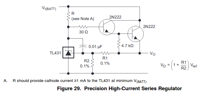
@rubypanther thinks that the purpose of the cap in the DCDC-MH circuit is soft-start or reduced transient responses. He might have a point, and it might not be unusual at all: the TI TL431 datasheet proposes a very similar circuit:
Stability and phase reserve of the TL431 seems to be an"interesting" problem for design engineers.
-
The DCDC-MH works (a hack while waiting for Santa)
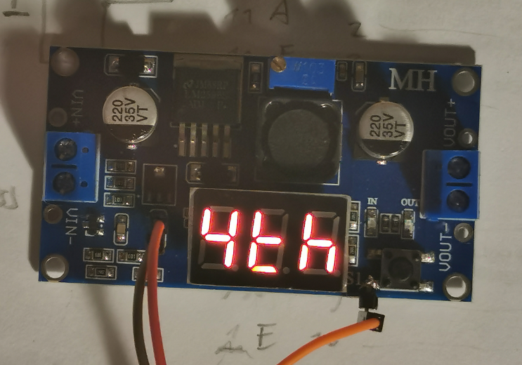
12/24/2019 at 17:29 • 4 commentsI tried out my new hot-air rework tool - replacing the µC works great!
![]()
I then traced a few signals (a first gist is here: https://gist.github.com/TG9541/666e421f80dfbc6cca5957238175bf08) and used the trusty W1209 binary as a starting point.7S-display, LEDs and key "S1" all work, and PD1/SWIM is used for half duplex console.
Here is the result:
![]()
Edit: gist updated (now including code).
In case someone wants to order a board: this seller seems to have the lowest price. -
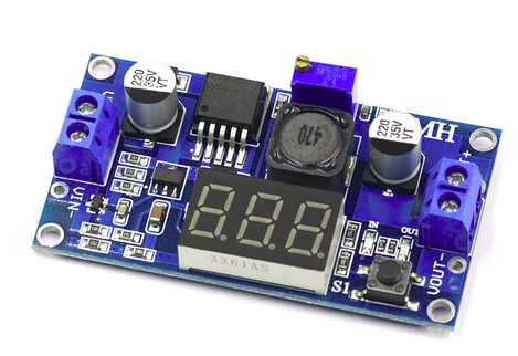
That's what you'll get today
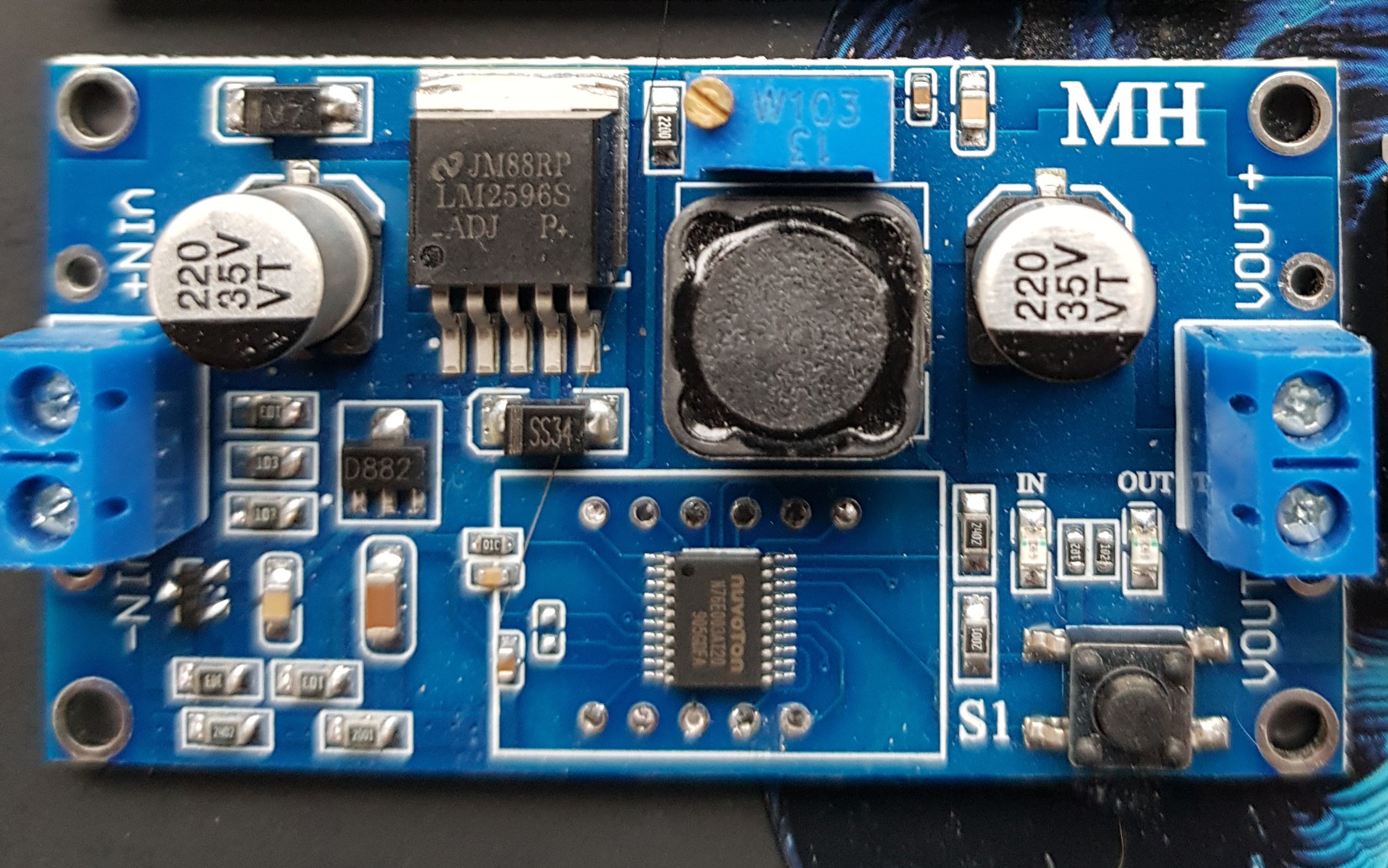
12/24/2019 at 13:08 • 0 commentsIt's been a while since I ordered two cheap DC/DC converters - today I removed the LED displays to see if it's hackable.
The second one, the one that looked most promising since the seller's pictures showed ICP pads, turns out to be disappointing:
![]()
First, there are no ICP pads. Second, the voltmeter is controlled by a combination of two chips. The SOIC-8 chip is a 24C02 EEPROM. I've got no idea why they removed the label from SOIC-16 part, but it's not worth bothering since it's unlikely that a µC without EEPROM would be worth hacking.
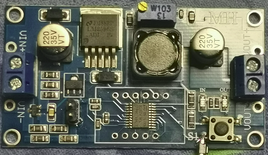
The second one looks much better: compared to the first specimen the Nuvoton replacement for our trusty hackable STM8S almost looks like a long-lost friend. The guy who made the PCB even was nice enough to keep the option of using an STM8S003F3P6: the unpopulated pads to the left of the µC are for the Vcap capacitor!
![]()
There is more good news: S1 is connected to pin18 - PD1/SWIM. I didn't test it but ut s likey that there is nothing besides the key connected to it. Of course, there is more to figure out before I it's clear that there is still life in hackable DC/DC converters (e.g. a free-ish GPIO with PWM). If someone wants to try it, here is a recent offer for €1.25 / $1.38 (free shipping!)
-
Going Shopping
07/27/2019 at 08:48 • 0 commentsIt's a fact that in the small world of super cheap electronics gadgets the STM8S003F3P6 has been largely superseded by the (more or less) electrically compatible Nuvoton N76E003AT20, an MCS51-style µC.
Chinese manufacturers are moving on. New designs appear, which are maybe easy to hack, maybe not. Replacing an TSSOP20 µC on a PCB isn't difficult, though, and I decided to give two new very cheap boards a try:
![]()
This one is available for $1.27 (incl. shipping); it clearly has a different circuit design than the ones explored so far in the HaD project. Since mo one west of China knows what's under the LED, I ordered one to figure that out. Maybe it's hackable.
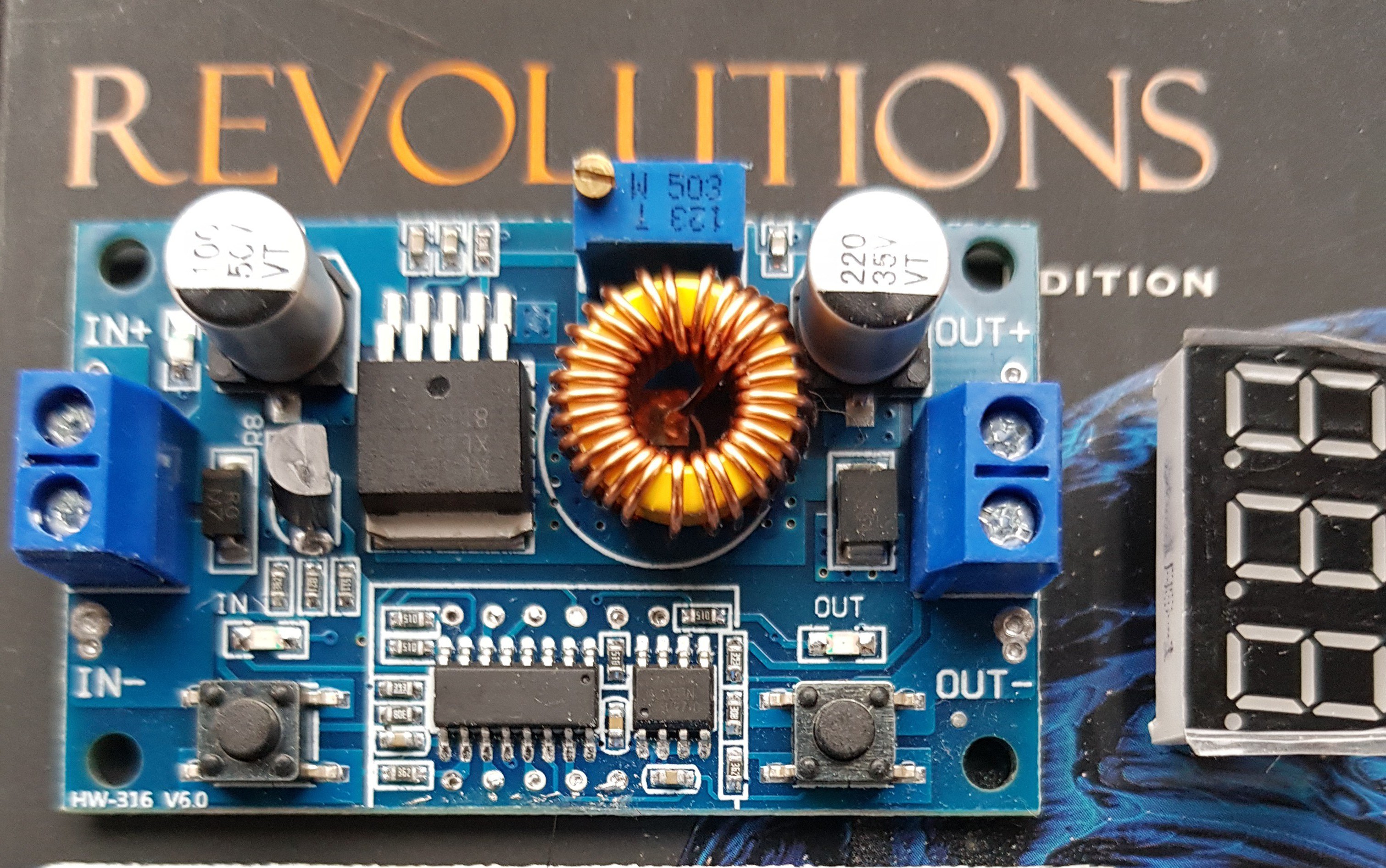
Another one uses a more modern DC/DC converter silicon, the XL4015, but otherwise it looks very similar to the old design:
![]()
What's promising is the ISP pads on the backside of the board that show a pattern typical for boards with STM8 µC. I don't really expect one there, but who knows. I've seen it for $1.65 (incl. shipping), and maybe I can hack it to run STM8 eForth.
-
Where to go from here?
10/22/2018 at 19:06 • 0 commentsThis project has been very quiet - to be honest about it I don't even know if the $1.50 modules available today still has a trusty STM8S003F3P6 or rather an incompatible (but a couple of cents cheaper) Nuvoton N76E003AT20 under the LED display. It's true, the STM8S003F3P6 chips are getting cheaper again, but as a buyer of "cheap gadgets" you should now be prepared to do some soldering.
However, STM8 eForth is alive and kicking, and with the code in this project, a $0.85 STM8S103F3P6 breakout board, and a $0.50 LM2596 module a programmable power supply can be built for ver,y little money. In fact, it's possible to control several LM2596 modules with one Forth module - which should be interesting for robustness tests use cases, like the one described here.
-
STM8 eForth 2.2.22-pre2: Improved Robustness of Serial Interface
04/15/2018 at 20:42 • 0 commentsAmong many other things (e.g. EVALUATE and IDLE Operation) the upcoming STM8 eForth 2.2.22 improves the communication robustness of devices that share the GPIO used for communication with the 7S-LED display.
The Wiki has also been improved. Check it out!
-
STM8 eForth 2.2.20 tested with the Low-Cost Programmable Power Supply
12/23/2017 at 22:51 • 0 commentsI just tested one of my green boards with the latest STM8 eForth 2.2.20:
- the improved e4thcom support works great, even though the communication uses the DP segment
- #require loads aliases for unlinked words from the folder out/DCDC/target
- even loading Manfred Mahlow's STM8 eForth VOC extension, which patches the core, works without problems
The packaging method with automated builds (Travis-CI) used in the W1209 data logging thermostat project works well, and I plan to use it for providing pre-build "programmable power supply" binaries.
-
STM8EF v2.2.15: e4thcom 2-wire mode improves DC/DC usabiliy
09/17/2017 at 18:29 • 0 commentsThe latest STM8EF release v2.2.15 contains a CN2596 DC/DC board binary that works great with the latest e4thcom STM8EF plug-in.
Here is a demo (asciinema garbled the console key input a bit):
![]()
Please note that the coding examples can now use the e4thcom Forth code #include & #require features. It's also possible to create binaries from the same code using the STM8S simulation feature of uCsim.
Low-Cost Programmable Power Supply
Chinese "LM2596 DC/DC buck converter with voltmeter" + "some wires" + "Forth" = "programmable power supply"
 I'm going to refer to to this diagram when discussing modding options.
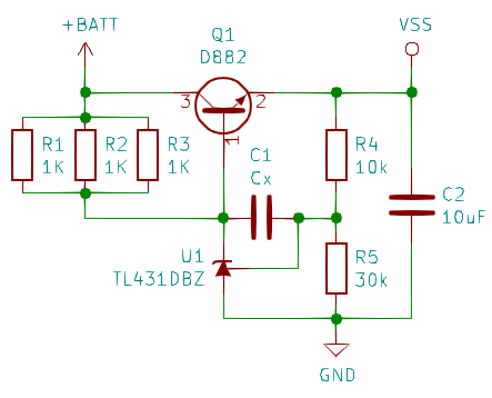
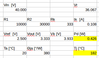 At 40V and a (hypothetical) ambient temperature of 20°C, the TL431 power dissipation is 30% above
 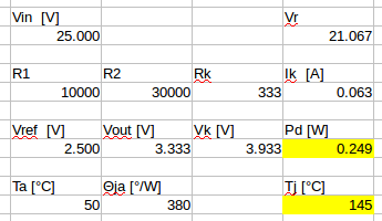 Since the temperature around the TL431 is bound to be closer to 50°C, an upper limit of 25V would be safer of the TL431 is to stay below the damaging junction temperature of 150°C.
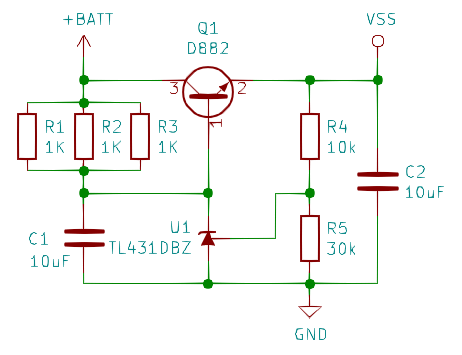
 Stability and phase reserve of the TL431 seems to be an