 Thomas
-
Script it: Forth Intro
06/01/2017 at 17:05 • 0 commentsForth is a very simple language, ideal for scripting, and therefore the Forth Intro in the GitHub Wiki also was simplified.
Check it out - feedback is welcome!
-
200 Followers!
05/19/2017 at 17:29 • 0 commentsNice, this little project seems to catch the attention of many of you!
It's really easy and cheap to hack the CN2596 DC/DC modules, and I can't wait to see on of these boards running your code, to do something useful, or to confuse a cat, I don't care :-) In any case, if you have questions just ask!
-
A Bug!
05/06/2017 at 08:40 • 0 comments@RigTig found a bug in tg9541/stm8ef that also affects this project: emiting a "Z" to the 7S-LED display shows an "S" while he's doing fancy things with the W1209. My bad. Bug fixed, but right now only in the develop branch. In other words, the base software is otherwise rather stable.
It's a bit quiet here because I'm currently bringing Forth to the HC12 wireless RS232 bridge. Robust communication to "smart things" in-house, on-premises or at > 500m in free space for about $3 and with very low power-consumption in stand-by mode.
-
Wiki Page on GitHub Updated
04/19/2017 at 18:22 • 0 commentsThe eForth for STM8 Wiki page on the CN2596-2 board has been updated. On this page I try to consolidate information dispersed here over comments and log entries.
If you think that something important is missing, please let me know!
-
100 Followers
03/31/2017 at 05:38 • 0 commentsNice, 100 people show interest in what was meant as a showcase project for the STM8 Value Line eForth project!
It's true, Forth differs a lot from procedural programing languages like Java, C++, C, Pascal, or Fortran. If you put the religious wars about programing languages aside, you'll see properties of scripting (Bash, BASIC, Perl, Python), REPL (LISP, Clojure), and ... assembly. It's not a panacea, but for some things it's very good.
I'd like to encourage you to get one or two of the green DCDC boards, an ST-LINK V2 adapter, and a serial interface adapter. With budget delivery, this will cost you about $4. It would be really nice to some companions on this journey, and to get some feedback about which features are needed most, or which points need better docs :-)
EDIT: 102 people now. Thanks guys! I forgot to mention the two capacitors and the two resistors. If you don't have an assortment in your lab anyway, here and here are examples for what you'd need for this, and for other projects (you may also ask a friend for some of these half-a-penny items).
Does someone know of a Hackaday page with recommendations for an "electronics starter kit"?
-
Cold Cranking (automotive ECU testing, homebrew style)
03/26/2017 at 11:24 • 0 commentsProgrammable power supplies are required (and expensive) test equipment in the automotive industry: the price tag for a single test channel can be several $1000 (and sometimes more).
You'll never hear me say that one can fully replace such a piece of equipment on-the-cheap, but it's always possible to use cheap equipment for doing a tests that support the development, and thus to reduce the risk that the stuff you develop won't pass the acceptance test. It's also sufficient for "exploratory testing", a method that's used in addition to verifying requirements (i.e. find out if known requirements are sufficient for higher level goals, like robustness or functional safety).
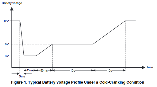
One of the common power cycle robustness tests for ECUs (automotive Electronic Control Units, e.g. motor control, body controller, brake control) is the cold cranking test. The "test pulse" (i.e. the effect on the power supply) looks like this:
![]()
Please note that the time scale in the first part of the function is in the order of miliseconds, and later in the order of seconds! The first part often induces a reset of an ECU (even if the requirements say that it shouldn't). No automotive embedded system I've heard of can operate valves (or other actuators) from 3V, but the 50 ms slope that follows serves to "stress test" ECU diagnostics. The 10s plateau then requires the ECU to rest in a "degraded mode" from which it has to recover somewhere in the 10s slope leading to normal operating conditions. Of course, the test pulse is just an acceptance test. For the automotive supplier, the objective is developing a robust ECU, not to meet the exact requirements.
I'll be using a $2 piece of equipment, a hacked CN2596-2 "DCDC converter with Voltmeter" operating on STM8 eForth.
The pulse can be generated by simply defining the output voltage as a function of time. I took the values from the chart and made a table for the STM8 eForth library word @inter in order to transform time in [ms] to voltage in [mV].
Thanks to the STM8 eForth Background Task creating a test pulse is very simple: all it takes is a task that converts the provided TIM value (ms ticks) with the help of a mapping function to a target voltage:
#require @inter

CREATE cctab
  6 ,
  12000 0 , , 3000 5 , ,
  3000 20 , , 6000 70 , ,
  6000 10070 , ,12000 20070 , ,

: coldcrank ( -- )
  TIM cctab @inter mV ;

' coldcrank BG !
CREATE defines the new word cctab, which returns the address of the following cells. In the following lines, the , take numbers from the data stack, and create a table by storing them in the dictionary memory (i.e. right after the word cctab. The word coldcrank gets the timer ticker value and the address of the table on the stack and uses @inter to get the value corresponding to the value of the 16bit ticker (in ms), and uses mV from the last log entry to set the output voltage. Negative values, and values > 20070 ms result in the saturation value 12000 mV (just like in the diagram). The pulse is thus repeated ever 65.536 s.
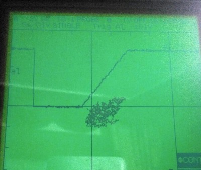
On my more than 20 years old damaged scope, the result looks like this:
![]()
If the picture doesn't show the initial drop in the diagram above. That's because time in the test pulse spec isn't to scale: on this scope a 70ms voltage drop to 3V all but disappears at a time scale of 5s/DIV.
The rising slope looks good (it appears to be linear, so the CN2596 hack works!), and also the two constant voltages (6V and 12V) look good. Discharging capacitors to 3V in just 5ms won't work without additional effort (with a 330R load the output voltage drops to 5V after 60 ms from where it rises to the plateau of 6V in about 20ms). Please keep in mind that this result was reached with a quick hack - it took longer to write this log, than to make this application work!
These guys from FIG were right, Forth is very effective, especially for building test equipment. For decades I only used C and assembly for embedded programming, and I had missed out on a very good tool.
EDIT: for discharging the output capacitor of the CN2596-2 board (220µF) from 12V to 3V in 5ms about 22R load is required. If the DuT (device under test = the test load) has a power rating of more than about 6.5W@12V that would always be the case. If the power rating is lower it depends: if the DuT has an ideal 3,17W DC/DC converter the 5ms slope in the test pulse spec could be met, too. Of course, most DC/DC converters are far from ideal, and a 22R/10W resistor with a generous heat sink can be added for safety.
EDIT: the example code now works with STM8 eForth 2.2.23 (#require for e4thcom, FILE/HAND removed). -
Linearized output
03/26/2017 at 08:58 • 0 commentsWith the interpolation routine from the last log entry linearizing the DCDC converter output is simple. It doesn't really matter how the function looks like: the grid point density can be adjusted to match the second derivative. In a first example, I simply used a voltmeter and the interactive Forth console to map PMW values to the output voltage. It turned out that between 0 and 1V the function is less smooth, and I inserted an extra grid point. Also, below 20mV I couldn't reliably control the output voltage (after all, a bias to the feedback ground of an LM2596 is a hack :-) ), so I set the last grid point to 469/20mV.
![]()
I decided to represent the voltage in units of mV, and created the following table with 14 grid points:
FILE NVM
CREATE vptab
14 ,
469 20 , , 451 500 , , 434 1010 , , 401 2000 , ,
367 3010 , , 333 3990 , , 297 5010 , , 261 5990 , ,
222 7010 , , 183 7990 , , 141 8990 , , 97 9990 , ,
50 11000 , , 0 12000 , ,
RAM HAND
The mapping of output voltage to PWM is simple:
FILE NVM
: mV vptab @inter pwm ;
RAM HAND
By typing eg. 7500 mV I get an output voltage of 7.53V, which is more accurate than I had ever expected. I observed some drift, but as there is nothing like reference voltage source, what can you expect?
Here are more examples:
5000 mV -> 5.02V
3700 mV -> 3.73V
3300 mV -> 3.35V
2800 mV -> 2.83VThrough the saturation feature of @inter the following works, too:
15000 mV -> 12.00V
-10000 mV -> 0.03VOnce more: level up!
-
Interpolation routine wanted (solved)
03/23/2017 at 06:25 • 10 commentsThis project calls for a robust and easy to use interpolation function, preferably one that accepts a list of (Xn,Yn) points sorted for ascending value of X. The result should be (Y0) for X < X0, and Ylast for X > Xlast.
If anybody has some code lying around or knows of some code that's been published under a permissive Open Source license, I would love to hear about it. Otherwise you'll just have to wait until a sufficient number of neurons in my brain isn't already fully satisfied by working on work related problems ;-)
EDIT:
I brewed something up. @inter includes the table search and the interpolation function @K.C. Lee referred to, and a limiting function that works by comparing the pointers to value pairs. It can be used for arbitrary y=f(x) with saturation, which is what's needed for many control and linearizion tasks.
: @dif ( a -- n )     \ delta of value pairs
  dup 2+ 2+ @ swap @ - ;
: @inter ( x a -- y ) \ find value pairs, interpolate
  dup @ 1- >R 2+ dup begin
    3 pick over @ < not while
    nip dup 2+ 2+ next
      drop dup
    else R> drop then \ eForth LEAVE idiom
  over = if           \ pointers equal: saturation
    2+ @ nip
  else
    dup rot over @ - over 2+ @dif
    rot @dif */ swap 2+ @ + then ;
@inter does a table lookup with interpolation. The input is the value and the address of a table with n value pairs (Xn, Yn) ordered by ascending values of X, and preceded by the number of n. @dif looks up two values returns the difference (X1-X0 or Y1-Y0 depending on the offset). A C program would be a bit longer, I guess. Compiled this code requires 177 bytes.
Here is an example:
500 1000 400 800 300 600 200 400 100 200 50 100 6 ok
create pairs , , , , , , , , , , , , , ok
: p pairs @inter . ; ok
450 p 225 ok
90 p 50 ok
1500 p 500 ok
pairs is an arbitraty list of 6 x/y value pairs: [6, [100, 50], [200, 100], [400, 200], [600, 300], [800, 400], [1000, 500] ]
Test values:
450 is between (400/200) and (600/300) -> result 225
90 is below X0, and following the requirements above Y0 is returned -> 50
1500 is above X(n-1) and Y(n-1) is returned -> 500 -
Instructions updated
03/18/2017 at 20:24 • 0 commentsRelease v2.2.8 on the TG9541/STM8EF on GitHub now has "official" support for the CN2596-2 DCDC converter as a Programmable Power Supply, and the instructions in this Hackaday project provide a (hopefully complete) step-by step guide.
In any case, if you need help, or if anything should be clarified, please let me know. I'm curious if anybody dares to invest $1.60 in this hack ;-)
-
CN2596-2 Board keys work (Forth 101)
03/14/2017 at 06:32 • 0 commentsThe CN2596-2 board keys (labeled "IN" and "OUT") are now supported.
I removed the LED "IN" from the word OUT!. With the B4-controls-LM2596-ONOFF mod, the DCDC converter can be switched on and off easily.
I'll describe the next steps in an update to this log entry later on. The code in TG9541/STM8EF develop branch is up-to-date.
EDIT: the development branch now contains ready-to-use DCDC code (i.e. with timer initialization, and the pwm output word).
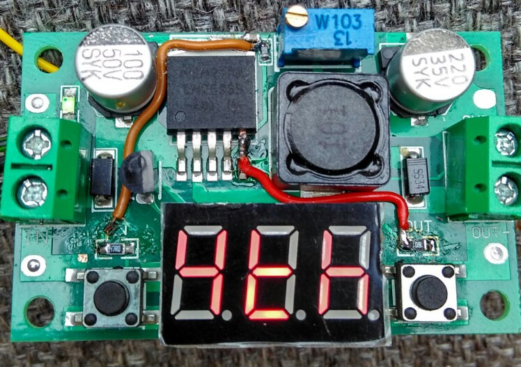
I also added ON/OFF control for the LM2596 through port PB4 (former LED "OUT"). The led got replaced by a 1.8k 0804 resistor as a pull-up, pin5 of the LM2596 was cut in the middle, and connected to PB4 (red wire).
![]() The following code toggles the LM2596 output voltage on and off when pressing the "IN" key:
The following code toggles the LM2596 output voltage on and off when pressing the "IN" key:
: b ?key if 65 = if out @ 1 + out! then then ;
' b bg !
A little explanation for C programmers: in Forth most of the dataflow happens on the data stack (it's maybe easier to understand for JavaScript programmers: the blank between Forth words is a bit like the . between jQuery filter words, and the stack corresponds to the $ object).
": b" defines word b. ?key puts "<key code>" and "-1" " on the stack if a key is pressed, and "0" otherwise. if takes a number from the stack, and goes to the next then if the value is "0". Inside the condition structure, = tests if the key code equals 65 and in the next if the value of the outputs register out is incremented to toggle bit0, and then written to PB4 with out!. Note that 65 is of course the ASCII code of "A" (key "OUT" corresponds to "B", and both keys pressed together is "C").
The operator ' (tick) put the address of b on the data stack. which is assigned to the background task vector BG with the store operator !. From there on b gets executed in the background in a 5 ms interval.
The while the code above runs in the background, the output voltage can be changed on the console interactively:
\ set maximum voltage (e.g. 12V, use trimmer to adjust)
0 pwm
\ set low output voltage (about 0.5 V)
450 pwm
As you may have guessed, \ is the comment operator for single line comments. pwm pops a value from the stack and sets the TIM1_CC3 compare register (the duty cycle of PC3 controls the ground level of the LM2596 feedback loop). Since the board init routine sets the Timer1 reload register to 1000, the compare value 450 corresponds to 45.0% duty cycle.
Low-Cost Programmable Power Supply
Chinese "LM2596 DC/DC buck converter with voltmeter" + "some wires" + "Forth" = "programmable power supply"

 The following code toggles the LM2596 output voltage on and off when pressing the "IN" key: