Close
0%
0%

Thumb Drive- Ryomen Sukuna Edition

Made an RGB USB Drive that is modeled after Ryomen Sukuna, completely from PCBs.

Public Chat
Similar projects worth following
0 followers
This is THUMB DRIVE, a portable RGB backlight that can be plugged into any USB port directly.
The whole Light board is made from two PCBs connected together using PCB standoffs.

The XIAO ESP32 C3 Dev board drives the WS2812 LEDs, which are positioned on the main board.

On top of the RGB LEDs, we have placed another board that is modeled after the cursed fingers of Sukuna from Jujutsu Kaizen. We modeled the finger after the character for aesthetic purposes.

Since we integrated USB pads directly onto the PCB, this board does not require an extra USB socket. The board can be directly plugged into a USB port and will function.

DESIGN

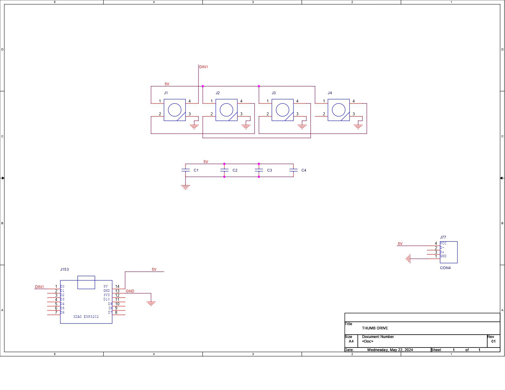
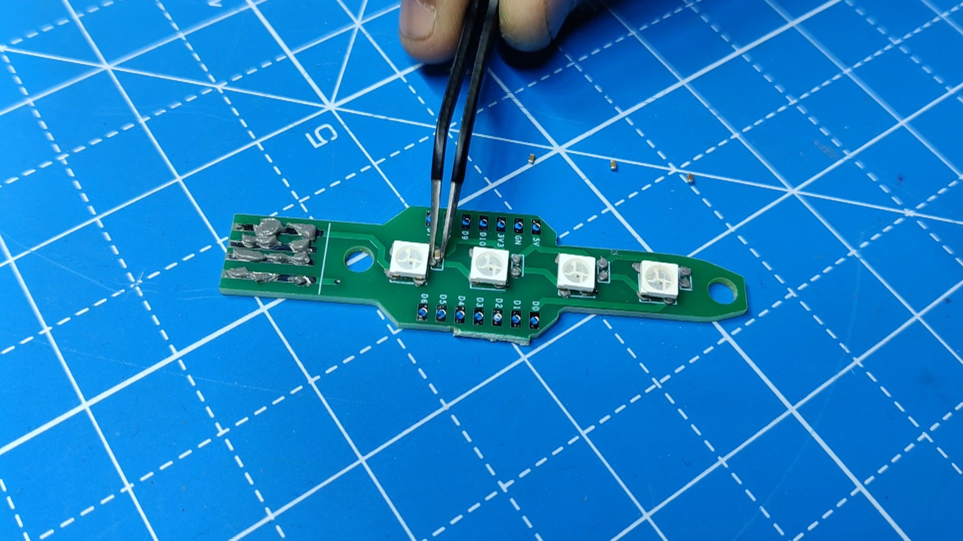
Initially, we prepare the PCB design for this project by creating a schematic with four WS2812 LEDs connected in sequence as well as four 100nF capacitors connected to the VCC and GND of the LEDs.

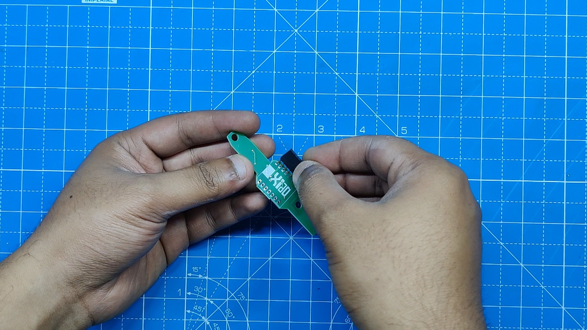
We added a XIAO ESP32 C3 DEV Board to control these LEDs.

Additionally, there's a CON4 port, which is actually the pad modeled after the USB port.

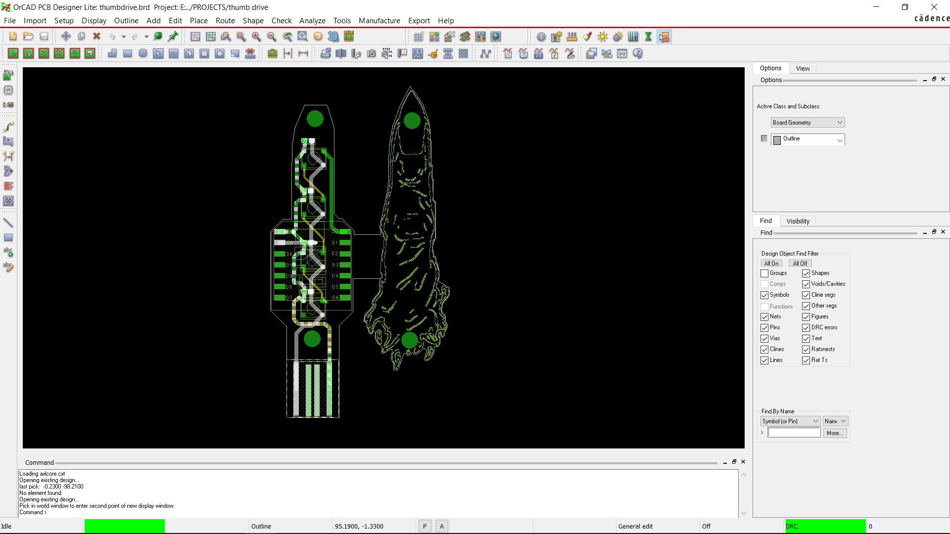
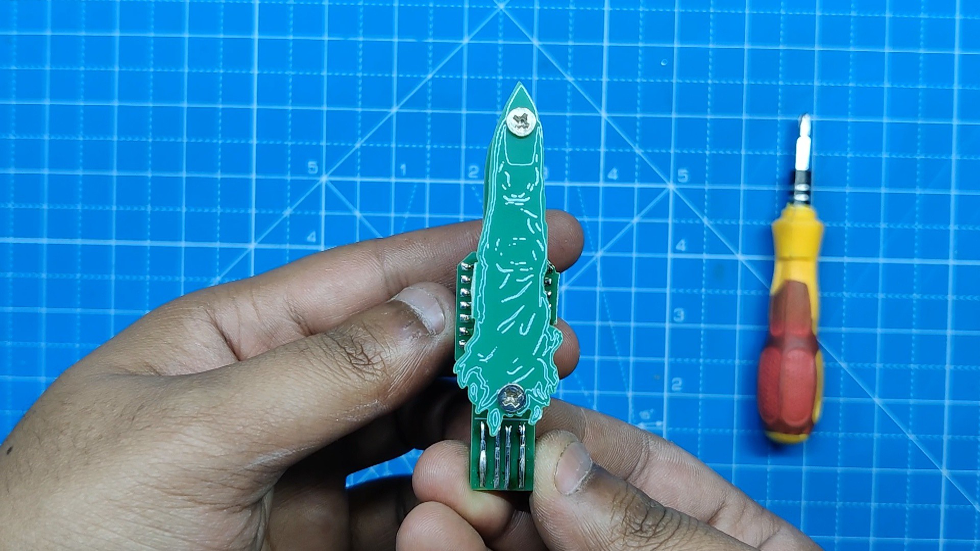
We initially uploaded the picture of the SUKUNA finger that we came across online after converting the schematic into board files in the PCB Editor. We uploaded the picture in BMP format to PCB Cad and then duplicated it to be put next to the original.

We edited the first image, which will become the main board that will house all the electronics, and the second image will be the SUKUNA finger board.

Here's something interesting: we placed two PCBs side by side and joined them together using a 10mm-wide rectangle, which will allow the manufacturer to make this board as a single PCB.

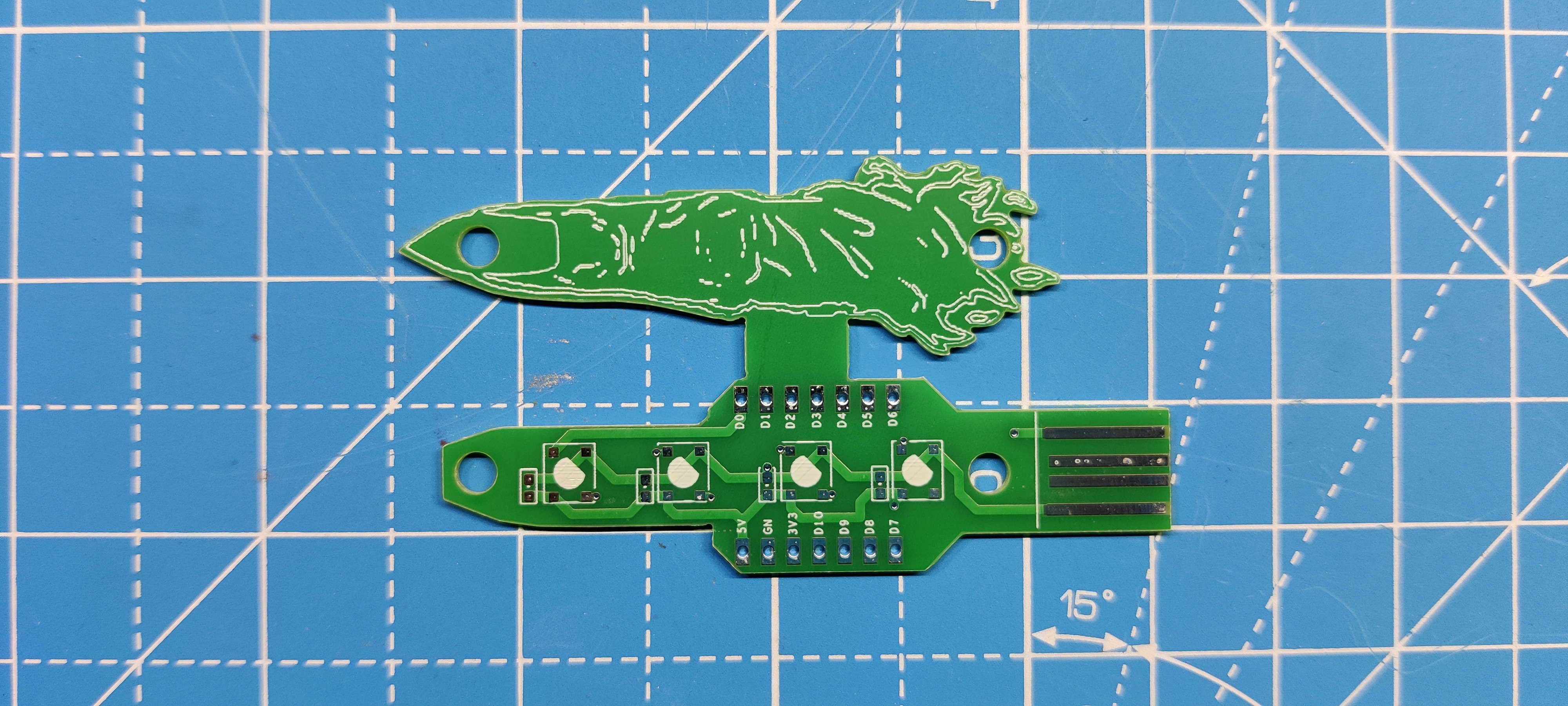
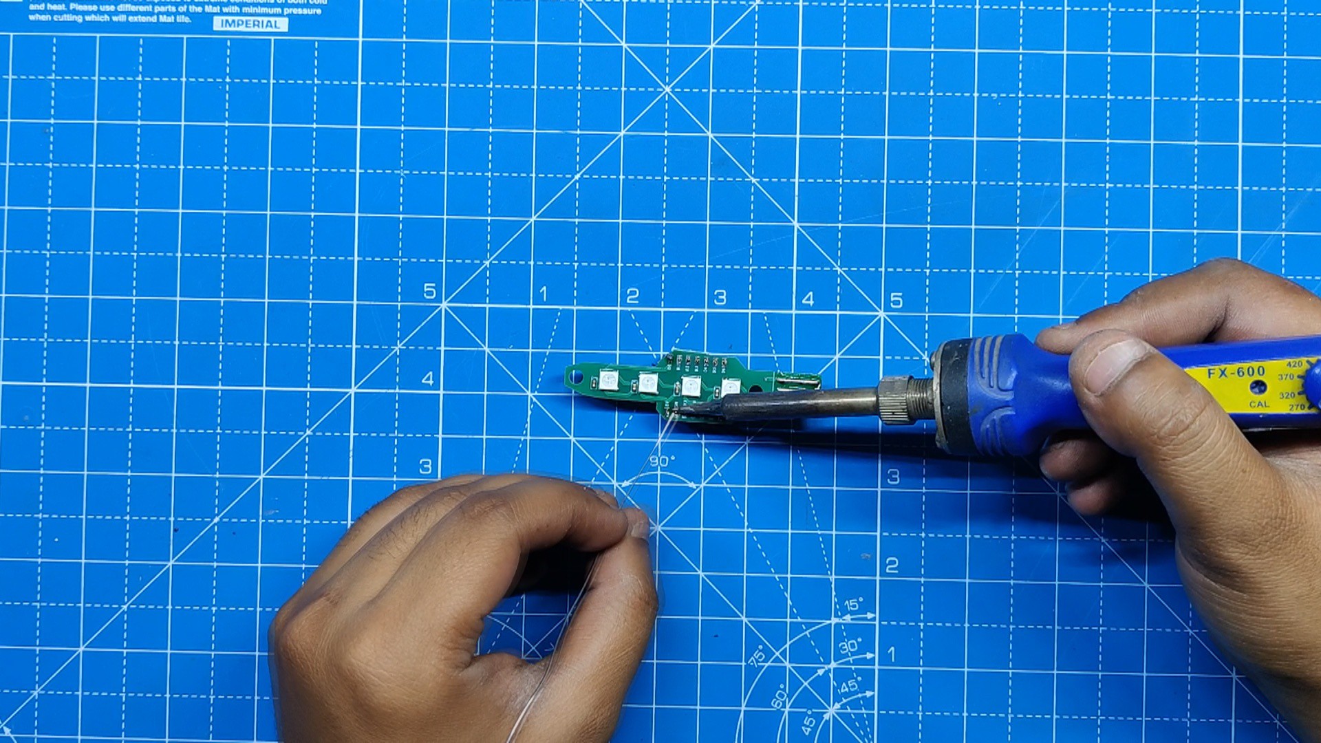
The idea here was to manually cut conjoined PCBs using a cutter.

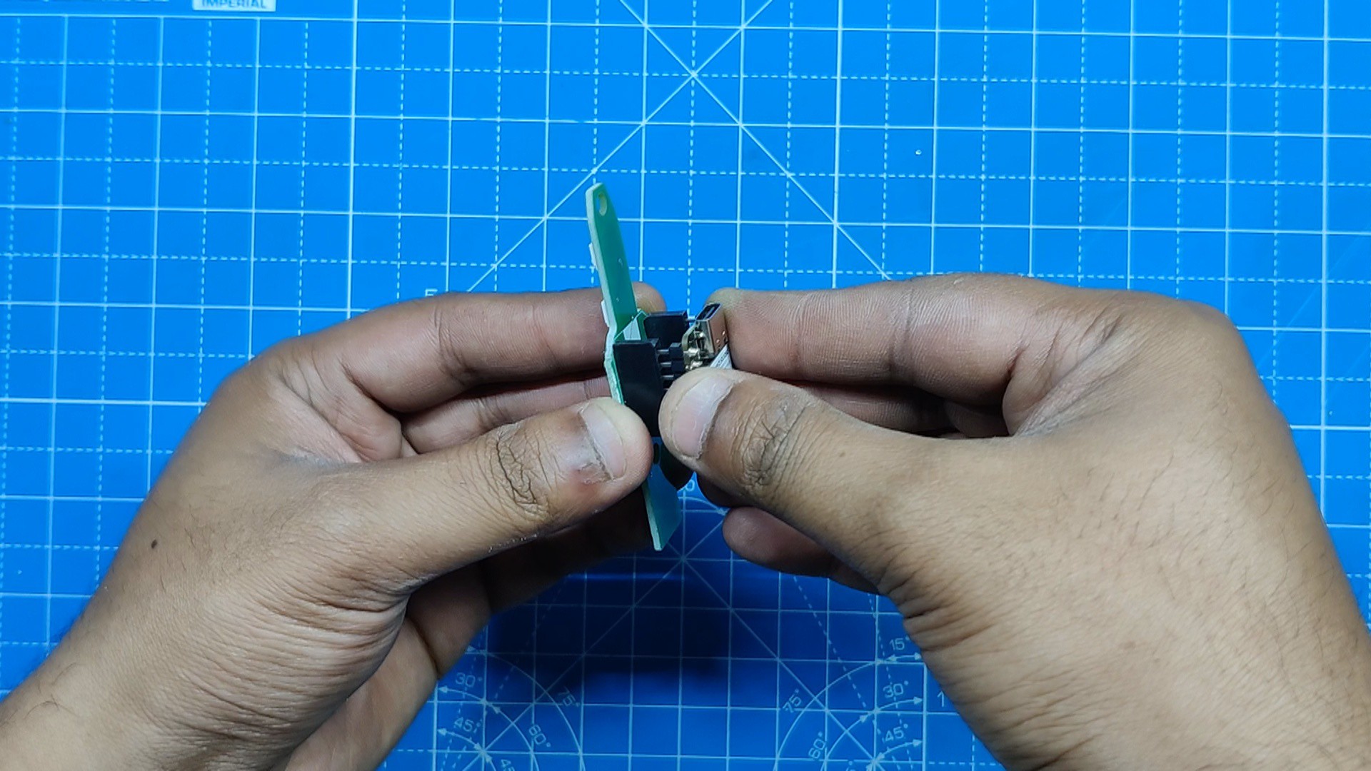
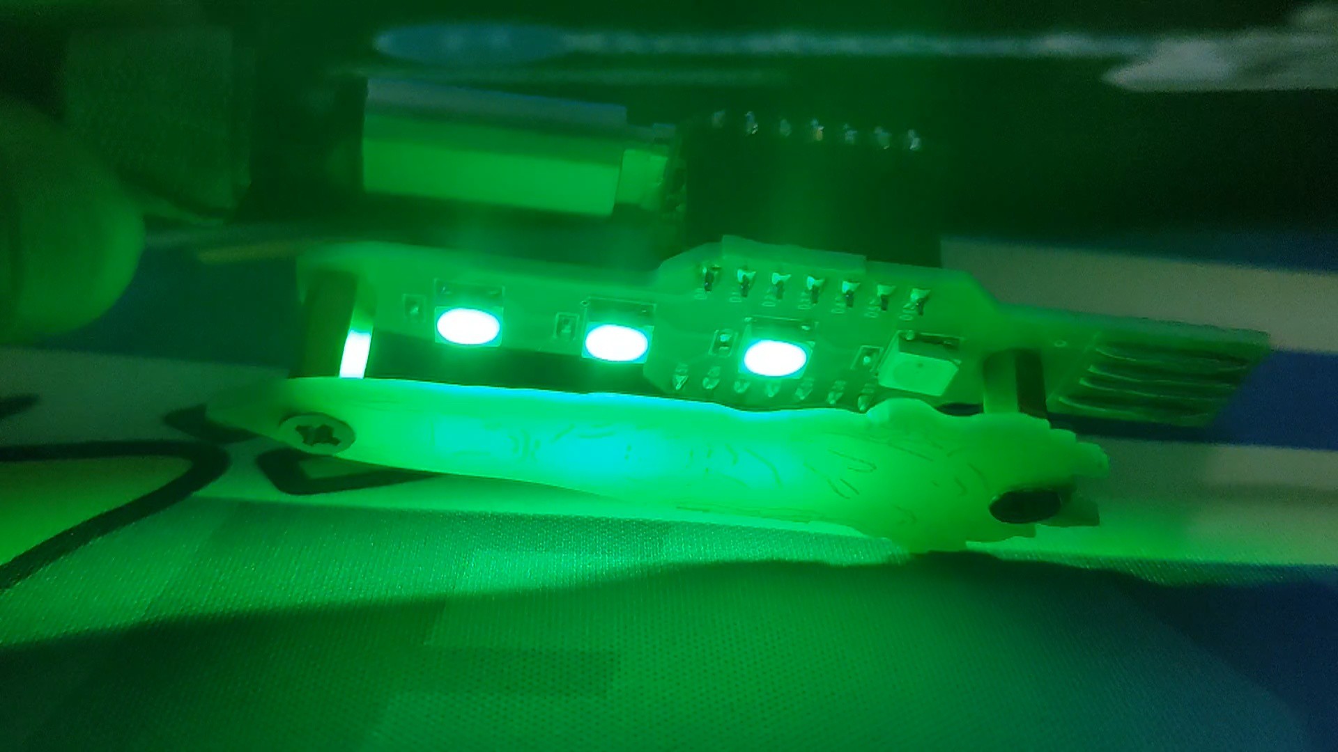
After dividing the single PCB into two pieces, we will place the finger board on top of the main board using M3 PCB standoffs. The top finger board will act as a diffuser for the RGB LED on the main board.

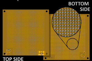
Additionally, the mainboard contains a custom USB pad, which was modeled after the actual position of the pins inside the USB port.

Seeed's Fusion Service

After the completion of PCB Design Process, we uploaded the gerber data for the PCB to Seeed's Fusion Site and ordered few Boards with Green Solder mask.

PCBs were received in a week, and their quality was super good considering the rate, which was also pretty low.

Seeed Fusion PCB Service offers one-stop prototyping for PCB manufacture and PCB assembly, and as a result, they produce superior-quality PCBs and fast turnkey PCBAs within 7 working days.

Seeed Studio Fusion PCB Assembly Servictakes care of the entire fabrication process, from Seeed Studio Fusion Agile manufacturing and hardware customization to parts sourcing, assembly, and testing services, so you can be sure that they are getting a quality product.

After gauging market interest and verifying a working prototype, Seeed Propagate Service can help you bring the product to market with professional guidance and a strong network of connections.

EDITED THUMB.rar

pcb gerber data

RAR Archive - 170.72 kB - 06/10/2024 at 09:16

Download

sch.pdf

Adobe Portable Document Format - 152.22 kB - 06/10/2024 at 09:16

Preview

  • 1
    PCB Assembly Process
    • Using a solder paste dispensing syringe, the solder paste is first added to the PCB during PCB assembly.
    • Next, we pick and place all the SMD components in their places using an ESD tweezer.
    • Following the pick and place procedure, we placed the PCB on the SMT Reflow hotplate, which heats the board from below to the melting point of the solder paste. The solder melts at that temperature, soldering every component to its pad.
    • The THT process followed next, which starts by placing the header pins in the XIAO Pads.
    • Using a soldering iron, we soldered the pads of the header pins, securing them in place.
    • At last, we added the XIAO ESP32 C3 in its place on the header pin, and the PCB assembly has been completed.
  • 2
    Final Assembly
    • We're using two M3 PCB standoffs, each 10 mm tall, to secure both PCBs together.
    • We start by adding the M3 PCB standoffs to the main board using two M3 bolts.
    • Next, we place the finger PCB on top of the PCB standoffs and secure it using two M3 bolts.
    • The assembly has been completed.
  • 3
    Test Sketch

    For testing the board, we first uploaded the below test sketch into the XIAO, which makes the green light turn on in a sequence.

    #include <Adafruit_NeoPixel.h>
    #ifdef __AVR__
     #include <avr/power.h> // Required for 16 MHz Adafruit Trinket
    #endif
    
    // Which pin on the Arduino is connected to the NeoPixels?
    #define PIN        D0 // On Trinket or Gemma, suggest changing this to 1
    
    // How many NeoPixels are attached to the Arduino?
    #define NUMPIXELS 4 // Popular NeoPixel ring size
    
    // When setting up the NeoPixel library, we tell it how many pixels,
    // and which pin to use to send signals. Note that for older NeoPixel
    // strips you might need to change the third parameter -- see the
    // strandtest example for more information on possible values.
    Adafruit_NeoPixel pixels(NUMPIXELS, PIN, NEO_GRB + NEO_KHZ800);
    
    #define DELAYVAL 100 // Time (in milliseconds) to pause between pixels
    
    void setup() {
      // These lines are specifically to support the Adafruit Trinket 5V 16 MHz.
      // Any other board, you can remove this part (but no harm leaving it):
    #if defined(__AVR_ATtiny85__) && (F_CPU == 16000000)
      clock_prescale_set(clock_div_1);
    #endif
      // END of Trinket-specific code.
    
      pixels.begin(); // INITIALIZE NeoPixel strip object (REQUIRED)
    }
    
    void loop() {
      pixels.clear(); // Set all pixel colors to 'off'
    
      // The first NeoPixel in a strand is #0, second is 1, all the way up
      // to the count of pixels minus one.
      for(int i=0; i<NUMPIXELS; i++) { // For each pixel...
    
        // pixels.Color() takes RGB values, from 0,0,0 up to 255,255,255
        // Here we're using a moderately bright green color:
        pixels.setPixelColor(i, pixels.Color(0, 150, 0));
    
        pixels.show();   // Send the updated pixel colors to the hardware.
    
        delay(DELAYVAL); // Pause before next pass through loop
      }
    }

View all 5 instructions

Enjoy this project?

Share

Discussions

Similar Projects

Does this project spark your interest?

Become a member to follow this project and never miss any updates