 Arnov Sharma
-
1PCB Assembly Process
![]()
![]()
![]()
![]()
![]()
- Using a solder paste dispensing syringe, the solder paste is first added to the PCB during PCB assembly.
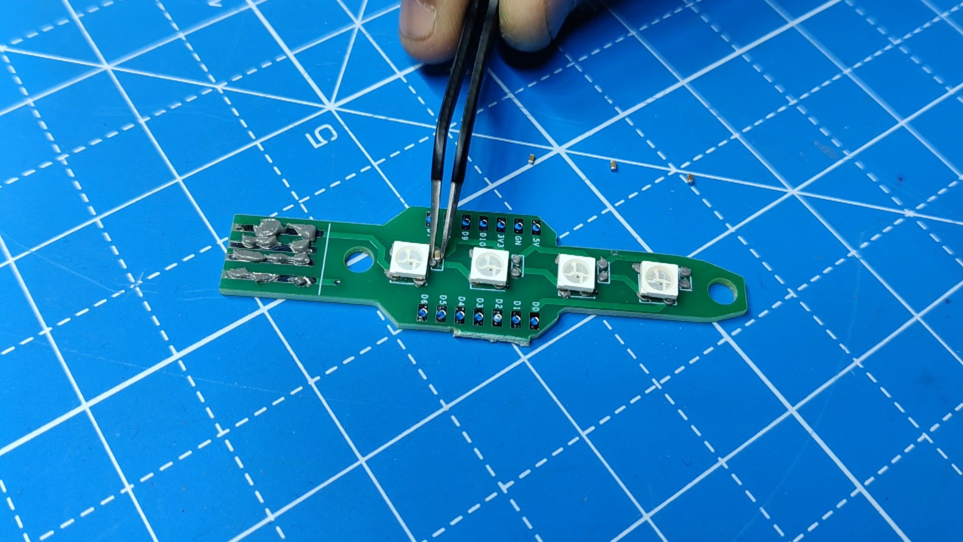
- Next, we pick and place all the SMD components in their places using an ESD tweezer.
- Following the pick and place procedure, we placed the PCB on the SMT Reflow hotplate, which heats the board from below to the melting point of the solder paste. The solder melts at that temperature, soldering every component to its pad.
- The THT process followed next, which starts by placing the header pins in the XIAO Pads.
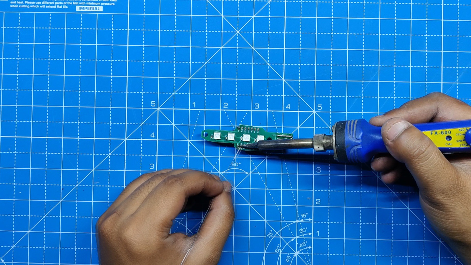
- Using a soldering iron, we soldered the pads of the header pins, securing them in place.
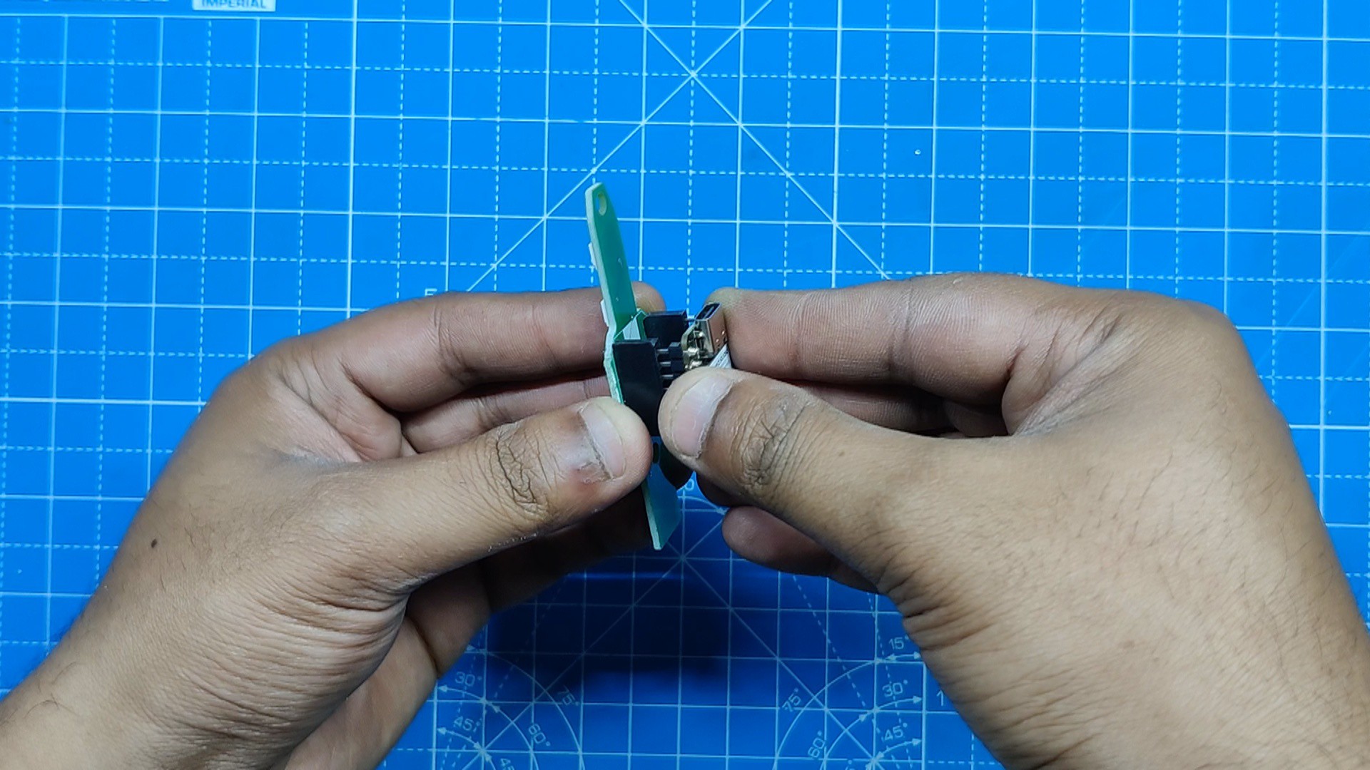
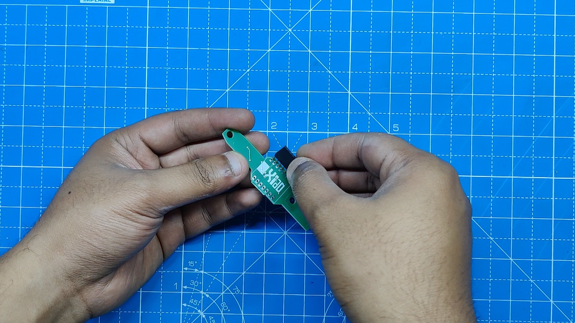
- At last, we added the XIAO ESP32 C3 in its place on the header pin, and the PCB assembly has been completed.
-
2Final Assembly
![]()
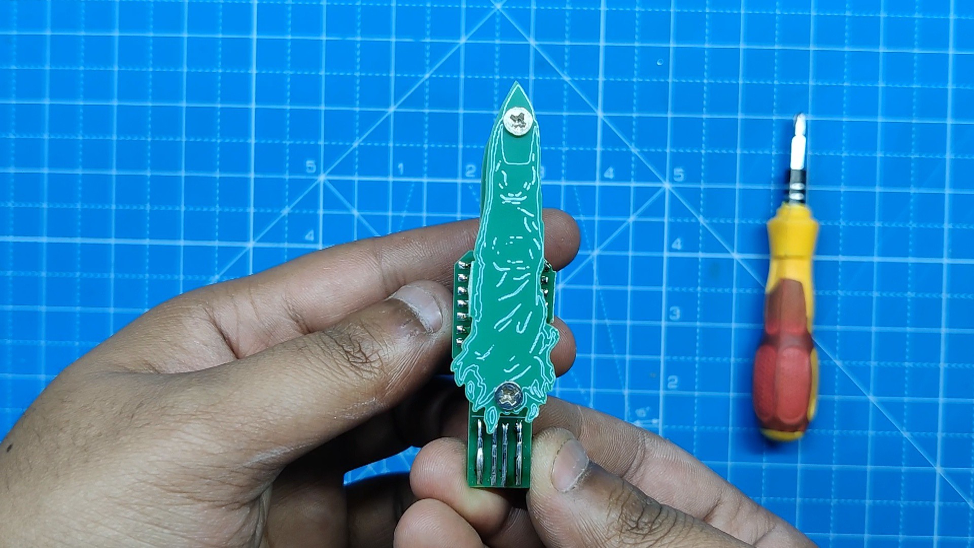
- We're using two M3 PCB standoffs, each 10 mm tall, to secure both PCBs together.
- We start by adding the M3 PCB standoffs to the main board using two M3 bolts.
- Next, we place the finger PCB on top of the PCB standoffs and secure it using two M3 bolts.
- The assembly has been completed.
-
3Test Sketch
![]()
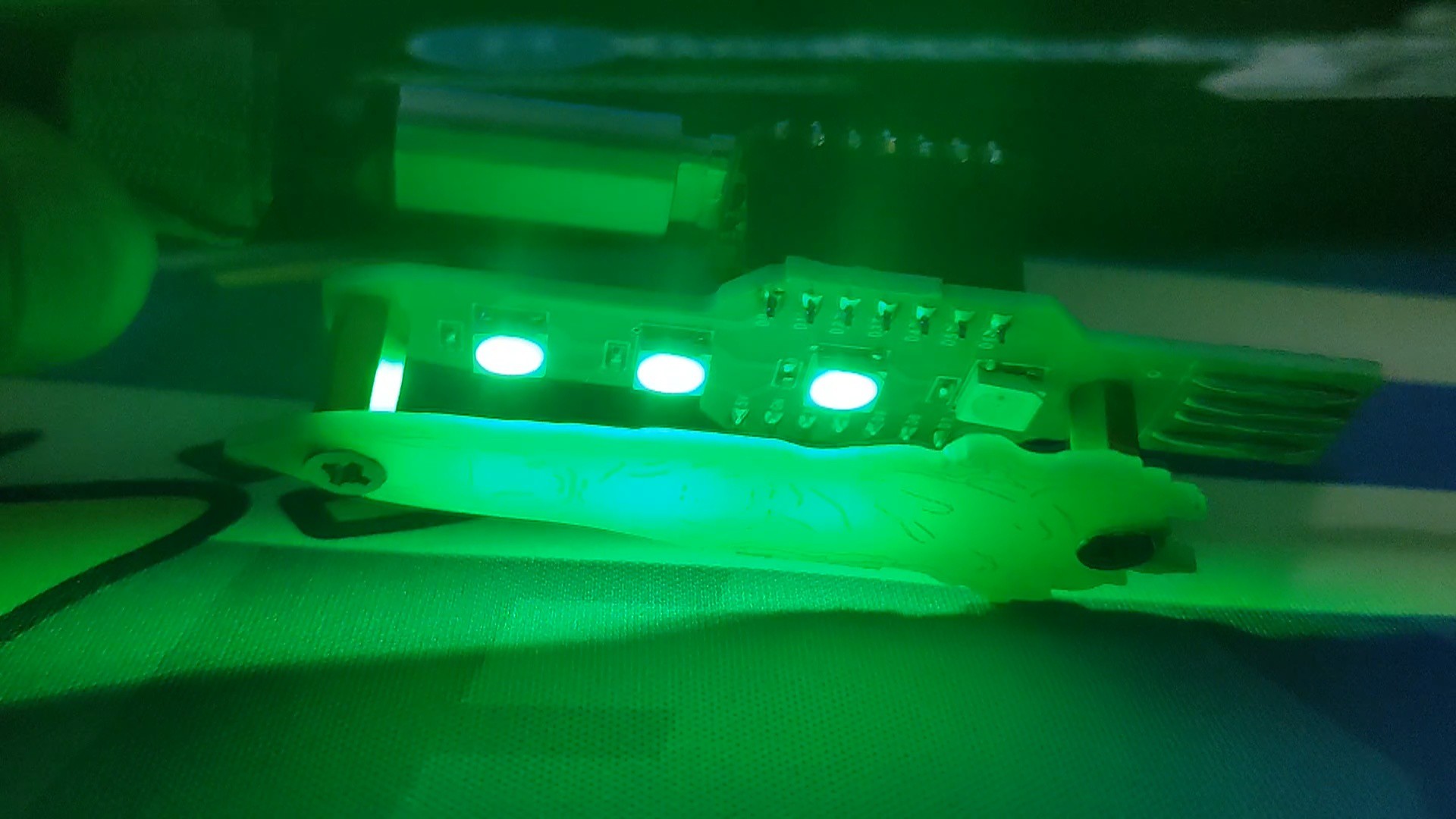
For testing the board, we first uploaded the below test sketch into the XIAO, which makes the green light turn on in a sequence.
#include <Adafruit_NeoPixel.h> #ifdef __AVR__ #include <avr/power.h> // Required for 16 MHz Adafruit Trinket #endif // Which pin on the Arduino is connected to the NeoPixels? #define PIN D0 // On Trinket or Gemma, suggest changing this to 1 // How many NeoPixels are attached to the Arduino? #define NUMPIXELS 4 // Popular NeoPixel ring size // When setting up the NeoPixel library, we tell it how many pixels, // and which pin to use to send signals. Note that for older NeoPixel // strips you might need to change the third parameter -- see the // strandtest example for more information on possible values. Adafruit_NeoPixel pixels(NUMPIXELS, PIN, NEO_GRB + NEO_KHZ800); #define DELAYVAL 100 // Time (in milliseconds) to pause between pixels void setup() { // These lines are specifically to support the Adafruit Trinket 5V 16 MHz. // Any other board, you can remove this part (but no harm leaving it): #if defined(__AVR_ATtiny85__) && (F_CPU == 16000000) clock_prescale_set(clock_div_1); #endif // END of Trinket-specific code. pixels.begin(); // INITIALIZE NeoPixel strip object (REQUIRED) } void loop() { pixels.clear(); // Set all pixel colors to 'off' // The first NeoPixel in a strand is #0, second is 1, all the way up // to the count of pixels minus one. for(int i=0; i<NUMPIXELS; i++) { // For each pixel... // pixels.Color() takes RGB values, from 0,0,0 up to 255,255,255 // Here we're using a moderately bright green color: pixels.setPixelColor(i, pixels.Color(0, 150, 0)); pixels.show(); // Send the updated pixel colors to the hardware. delay(DELAYVAL); // Pause before next pass through loop } } -
4Main Code
![]()
Here's the main sketch that we used in this project, and its a simple one.
#include <Adafruit_NeoPixel.h>
#define PIXEL_PIN    D0
#define PIXEL_COUNT  4

Adafruit_NeoPixel strip = Adafruit_NeoPixel(PIXEL_COUNT, PIXEL_PIN, NEO_GRB + NEO_KHZ800);

void setup() {
  strip.begin();
  strip.show(); // Initialize all pixels to 'off'
}
void loop() {
rainbow(20);
}
void rainbow(uint8_t wait) {
  uint16_t i, j;

  for(j=0; j<256; j++) {
    for(i=0; i<strip.numPixels(); i++) {
      strip.setPixelColor(i, Wheel((i+j) & 255));
    }
    strip.show();
    delay(wait);
  }
}
uint32_t Wheel(byte WheelPos) {
  WheelPos = 255 - WheelPos;
  if(WheelPos < 85) {
    return strip.Color(255 - WheelPos * 3, 0, WheelPos * 3);
  }
  if(WheelPos < 170) {
    WheelPos -= 85;
    return strip.Color(0, WheelPos * 3, 255 - WheelPos * 3);
  }
  WheelPos -= 170;
  return strip.Color(WheelPos * 3, 255 - WheelPos * 3, 0);
}
This code will result in a smooth, cycling rainbow effect on a NeoPixel LED strip connected to an Arduino, with each color smoothly transitioning to the next.
-
5Result
![]()
![]()
![]()
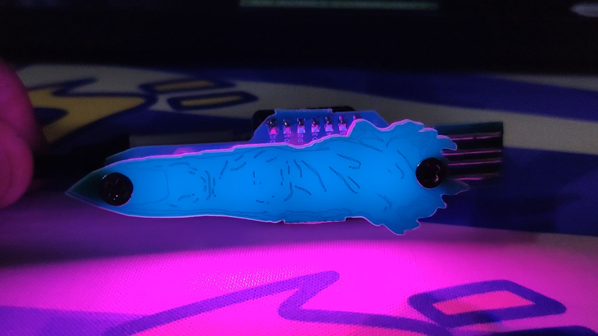
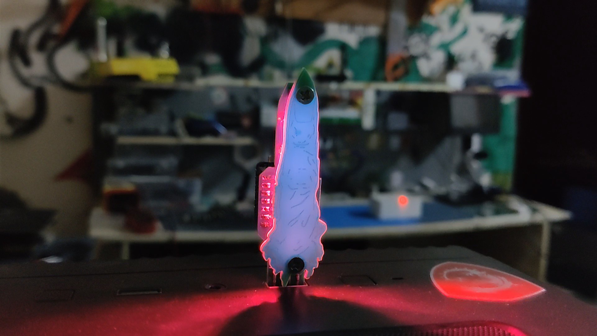
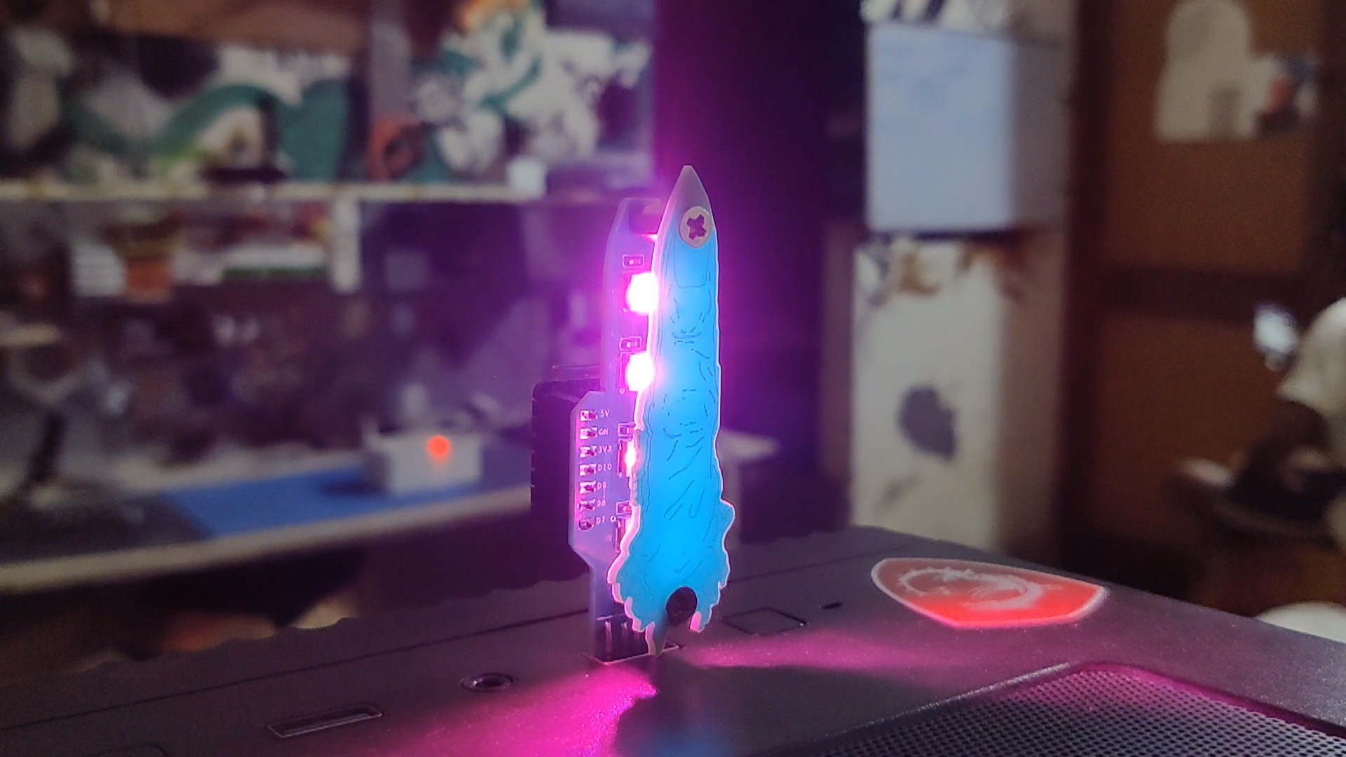
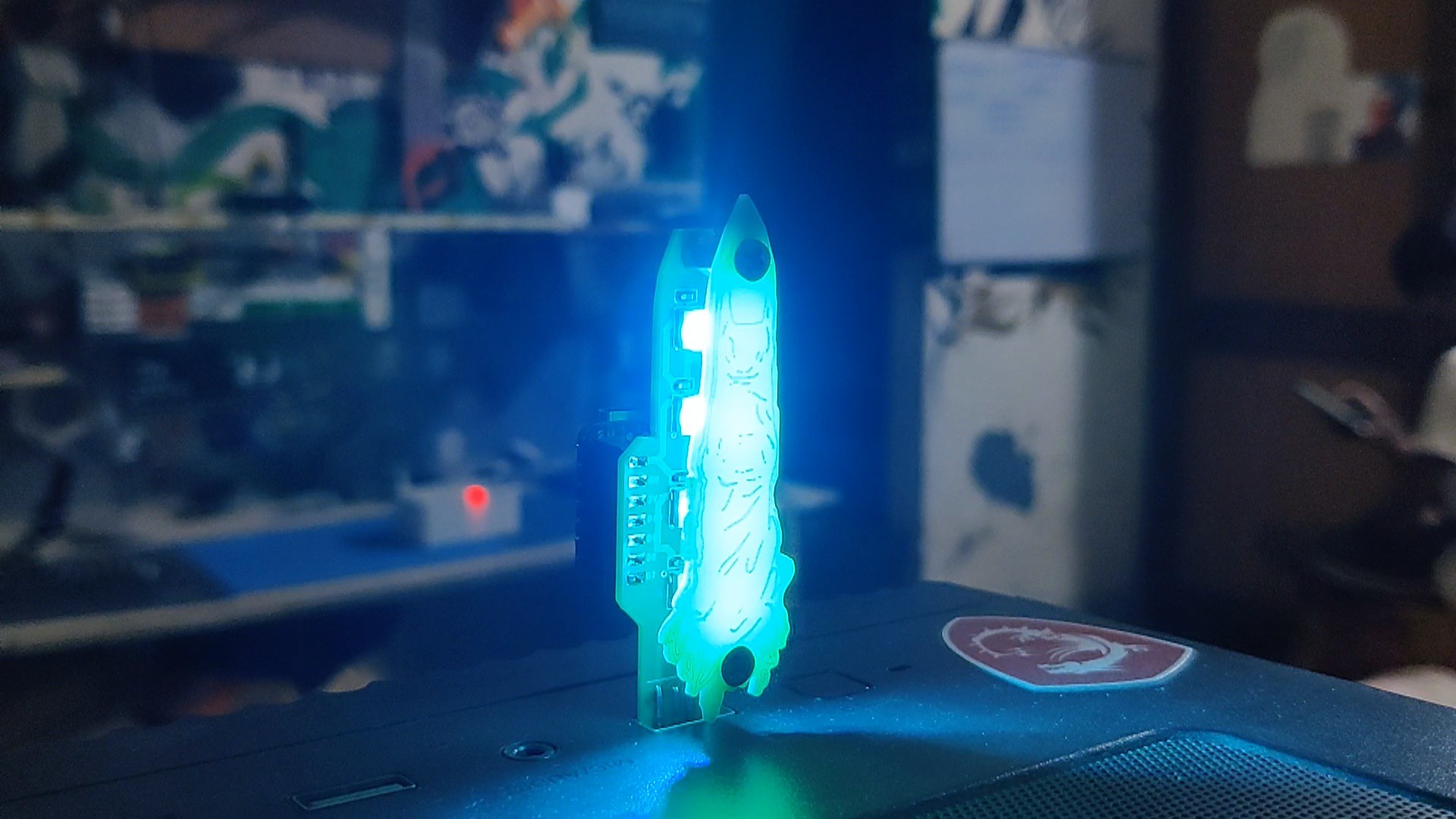
Here's the result of this simple yet fun build: a working Glowing Sukuna's cursed finger made completely from scratch using custom PCBs and the XIAO ESP32 C3 MCU.
We can add this device anywhere where there's any USB port. For example, we can attach this board to a TV or monitor, and it will glow up the background of the monitor or TV, which will look pretty good and be aesthetic.
We can also connect this board to a smartphone charger's USB port and use this device as an RGB lamp.
Overall, this project is working and requires no further revisions.
Leave a comment if you need any help regarding this project. This is it for today, folks.
Thanks to Seeed Studio for supporting this project.
You guys can check them out if you need great PCB and stencil service for less cost and great quality.
And I'll be back with a new project pretty soon!
Thumb Drive- Ryomen Sukuna Edition
Made an RGB USB Drive that is modeled after Ryomen Sukuna, completely from PCBs.

Discussions
Become a Hackaday.io Member
Create an account to leave a comment. Already have an account? Log In.