 mkdxdx
-
1Open it up
Meet the victim: beginner-level FPV goggles from BetaFPV.
![]()
Remove antenna, remove SD card, remove all visible screws so you will be presented with primary electro-optical block. You are interested in main electronic board:
![]()
-
2Cut the trace
Grab your knife and steady your hands before proceeding:
![]()
I must warn beforehand that this is not the optimal way functionally, but this is the easiest for our purpose.
I've only figured out one trace that is easily accessible for cutting - and it leads from buffer/switch IC and to LCD controller to the right.
Splicing into this part will allow you to switch external signal to LCD, but you will not be able to record external signal to DVR - it will still record whatever VRX is tuned on. RSSI indicator will also only detect whatever VRX outputs. Feel free to probe around to see if there is a better way to cut VRX video output before doing your hack - maybe it is much easier than i thought.
Now onto some surgery.
You are interested in this trace over here:
![]()
-
3Bodge it on
Heat up your solder and make some prepared wire.
You will solder one to VRX GND terminal, other wire goes to "To LCD" exposed copper area that was made bare in previous step.
If you decided to have switchable solution - this wire goes to "common" switch pole. In this case you will also need to add another wire to "From VRX" and solder it on to one of the switch NO/NC poles so you will be able to select your current channel.
![]()
Now for some miscellaneous notes.
Initially I looked up for some markings of chips that i saw there. One was TVP5150AM1 decoder which had video input on its first pin.
So naturally, i thought - this was it, because that passive circuit before it looked exactly like analog video input - it starts with 75 Ohm load resistor to the ground, then some filtering and then it ends up in this decoder chip.
But when i cut it and tested if LCD displayed what i wanted - what saw there was that i made a mistake. It still diplayed whatever VRX was tuned on and when i tried to record DVR - SD card had a file that displayed what was fed through my added wire.
And that is how i figured out that that whole area is actually DVR block (sure, as if SD card slot module was not enough).
And that is how Bridge of Shame was born, before i probed around to find how switch IC is wired and mended that cut i've made before.
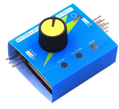
Also, if you are feeling fancy, to switch a video signal properly - you will need a video multiplexer chip that is adequately buffered and has all the bells and whistles on it's inputs and outputs. There are readily available video switcher modules in RC hobby and they look like this:
![]()
This will give you more clean signal (not that this solution does not) and properly saves every other involved part in the circuit from sudden static bursts and such. But these things, although cheap, also require additional control. These modules on the picture, for example, are controlled by either IBUS/SBUS signals, or by Servo PWM - which are available on RC craft, but for this project you will need to slap together something that outputs exactly that. And it also a powered circuit, that will put more drain on your already feeble FPV goggle tank.
You can make goggles with servo tester module look cool, though - and it also totally works for video multiplexer modules for RC hobby. Twist that knob, beauty.
-
4Add ergonomics
After you have soldered that "To LCD" wire - you are basically done and ready to connect it to any CVBS PAL/NTSC video output, in my case it was video out of HDMI converter.
But to make the thing a bit tidier, i've added this little breadboard with terminal and also a switch. I've only had three pin terminal which is excessive, but whatever, here is the wiring:
![]()
GND goes to GND terminal on VRX. This terminal also is the common (or shield) input alongside with Aux IN. Grab your RCA connector (preferrably with screw terminals) and RG316 cable and mash everything together - shield goes to GND/-, core/center goes to Aux IN/+. This is how you connect to your video source.
And all neatly placed into this slot which goggles have in the front part:
![]()
-
5Test it out
If everything wired correctly and you have applied enough flux/solder on those bare traces, when Aux In is connected to external unpowered input (if HDMI converter is connected but does not have input, for example), LCD chip sees that there is no signal, and displays your typical colored stripe image - something that is unusual for these goggles but is totally expected when you are dealing with LCD controller boards:
![]()
That means you are on the right track. If not - recheck previous steps and keep your "postponed indefinitely bin" close. Just in case. Failure is part of the process, baby.
Next step - boot up your application of choice and enjoy it in it's full analog glory:
![]()
But since that video format was made for motion picture - you better look for video in details of the project description.
-
6Pack it up
Take it back together, because it's much better that way.
![]()
-
7More ergonomics
Latest log describes more steps under the break to harden the build.
Adding aux video input to BetaFPV VR03 goggles
a 5 minute adventure to impruin your first FPV kit


Discussions
Become a Hackaday.io Member
Create an account to leave a comment. Already have an account? Log In.