 Arnov Sharma
-
1PCB Assembly Process
![]()
![]()
![]()
![]()
![]()
![]()
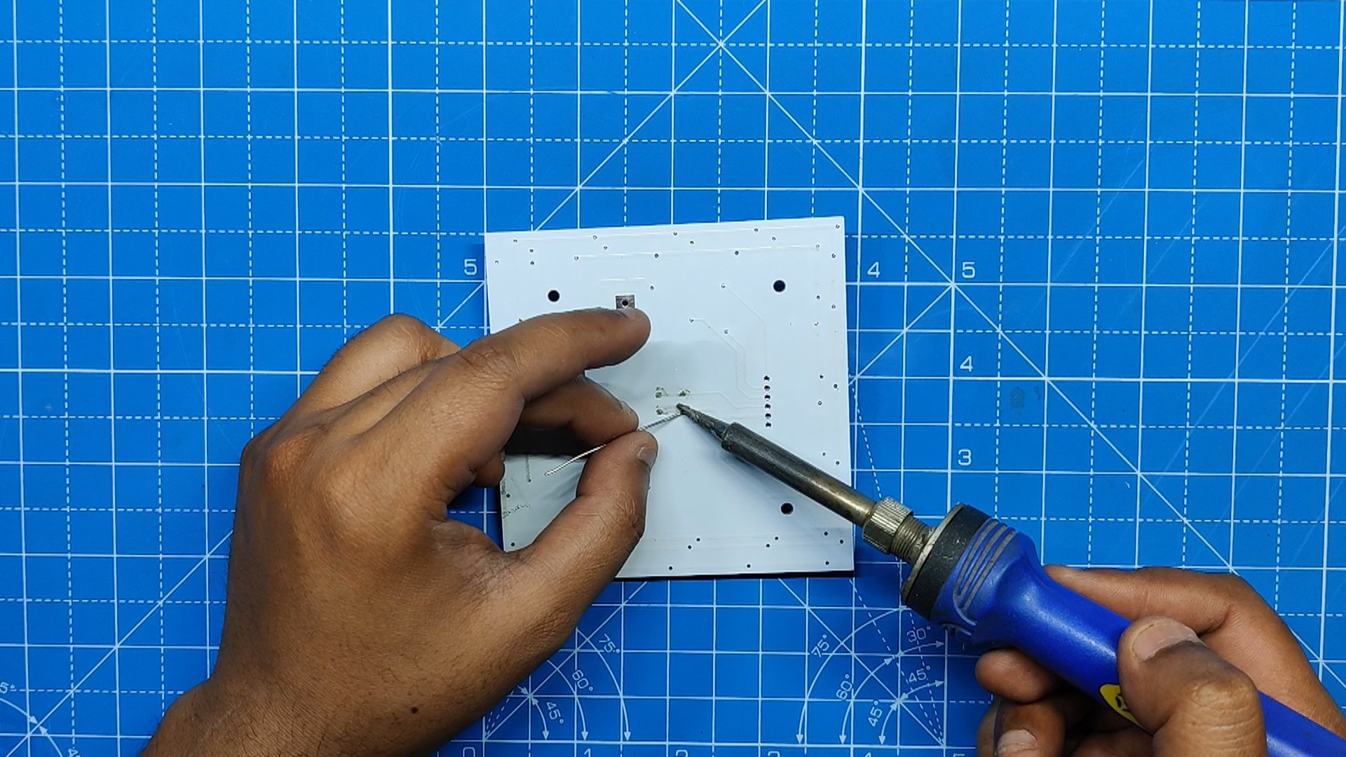
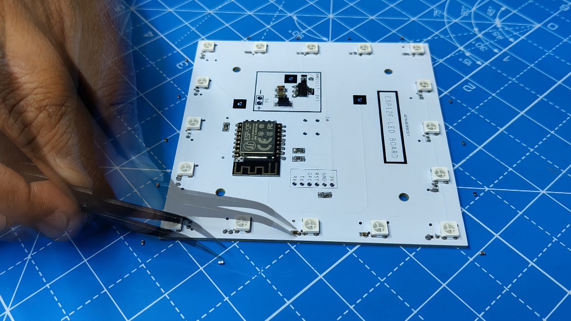
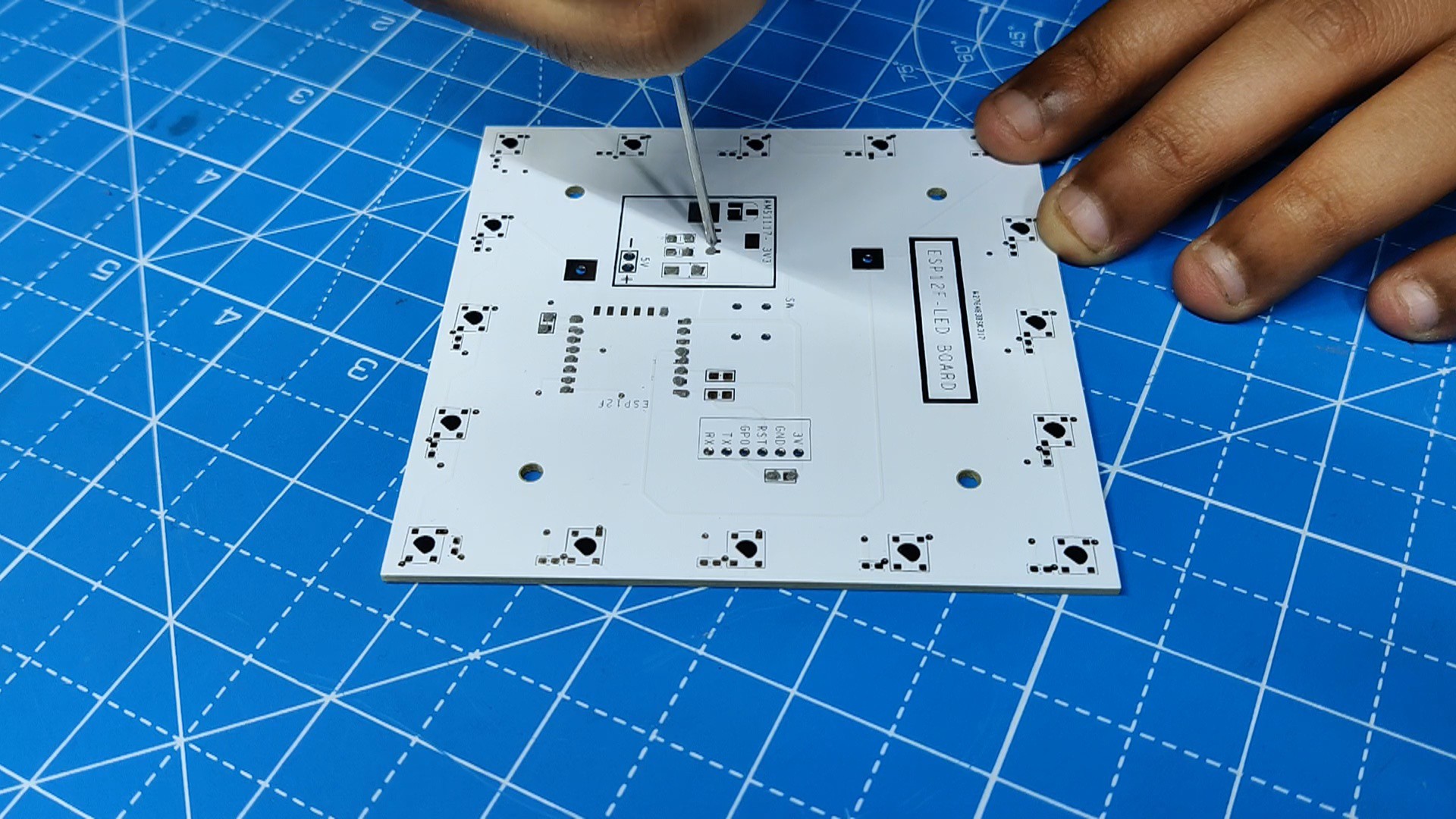
- Using a solder paste dispensing needle, we first add solder paste to each component pad, one by one. We're using standard 37/63 solder paste here.
- Next, we pick and place all the SMD components in their places on the PCB using an ESD tweezer.
- With extreme caution, we lifted the complete circuit board and placed it on the SMT hotplate, which increases the PCB's temperature to the point at which the solder paste melts and all of the components are connected to their pads.
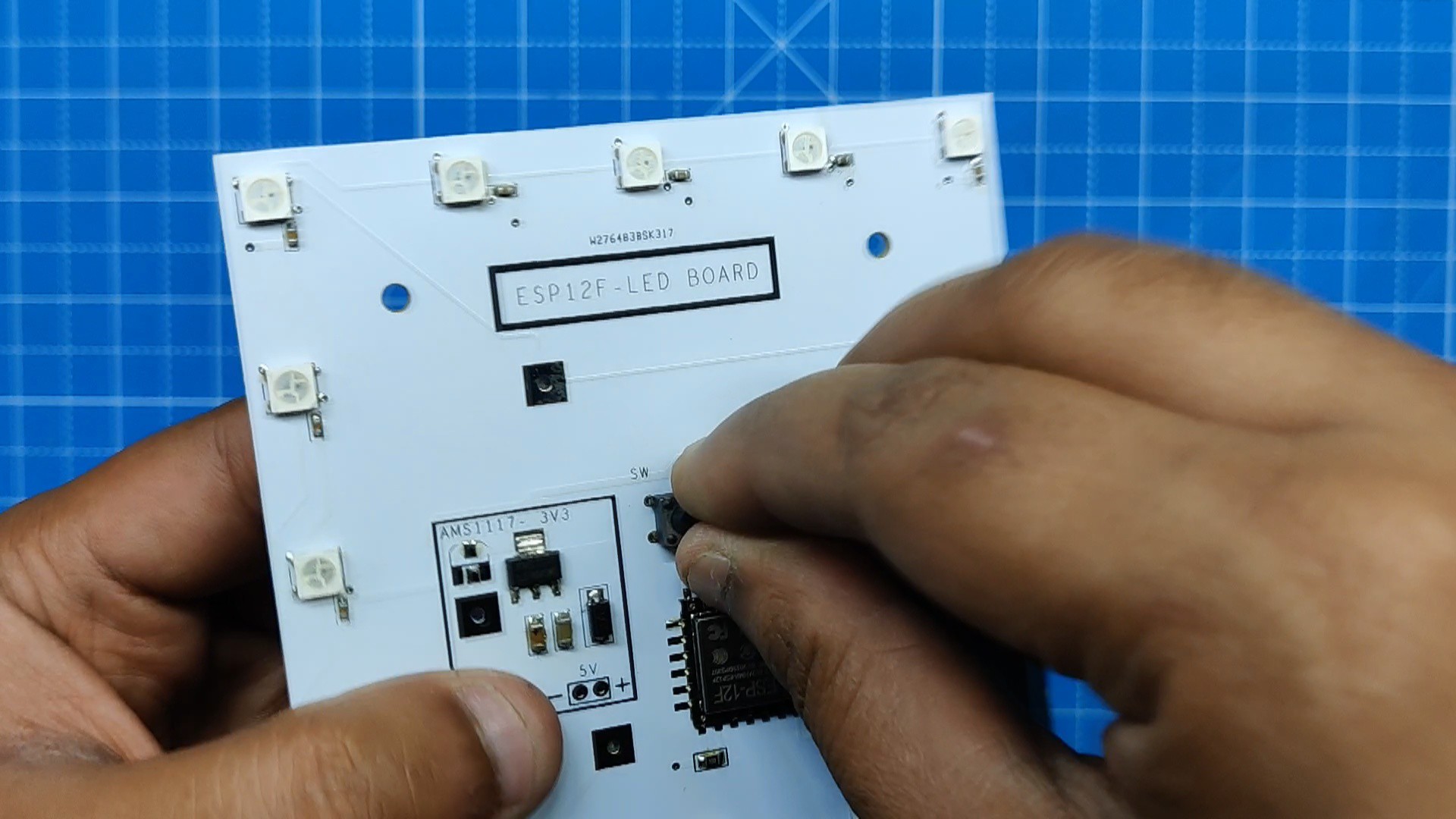
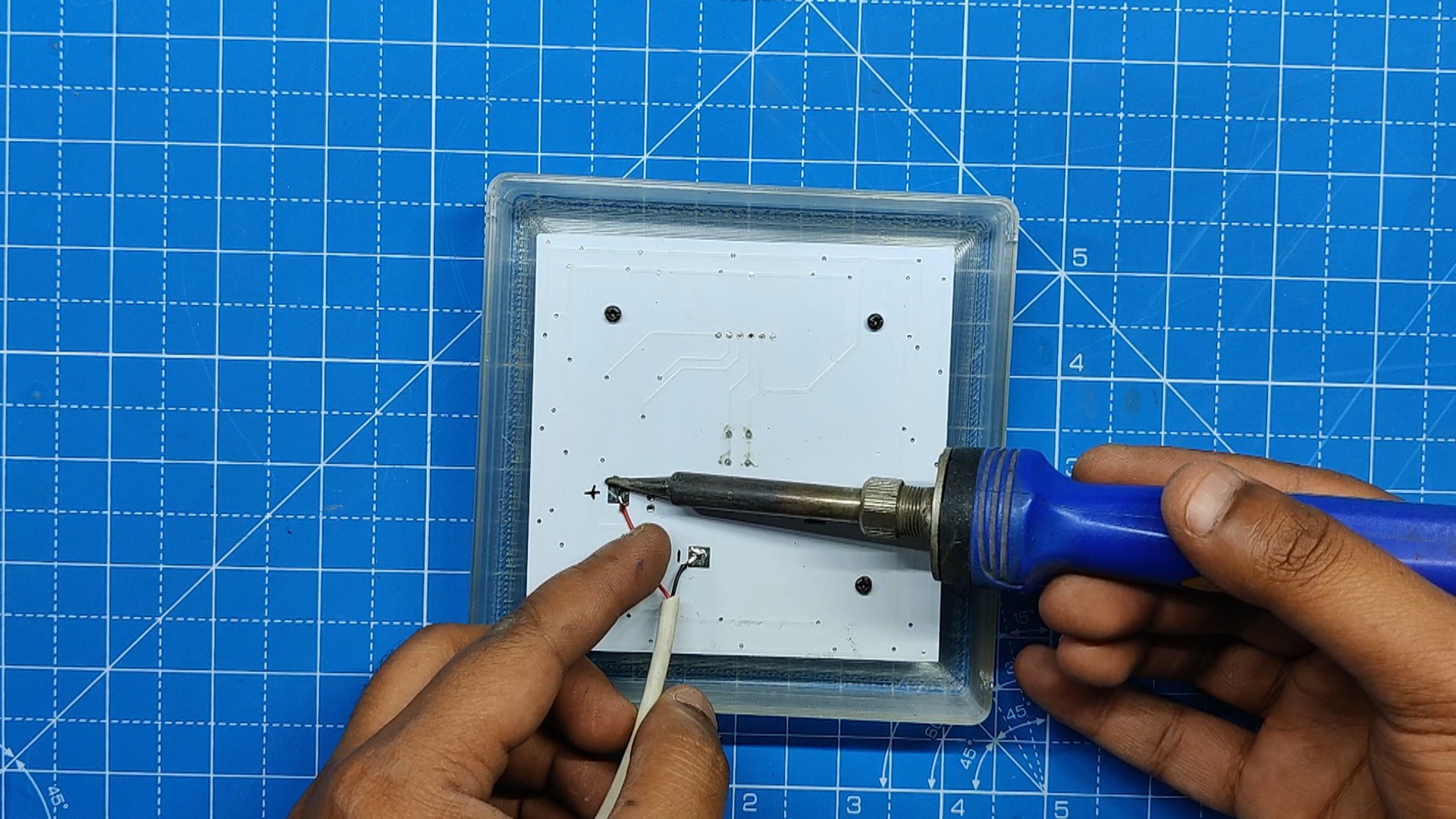
- At last, we added the THT Tactile Switch in its place and used a soldering iron to solder its pads.
PCB assembly is now complete.
-
2Flashing the ESP8266-Test Sketch
![]()
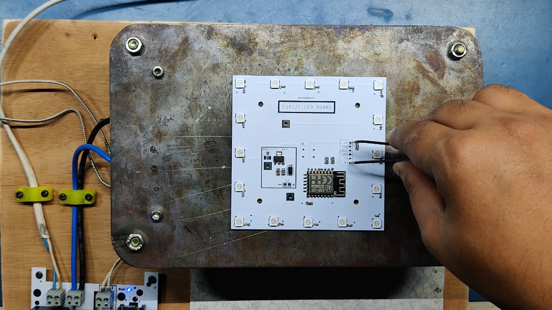
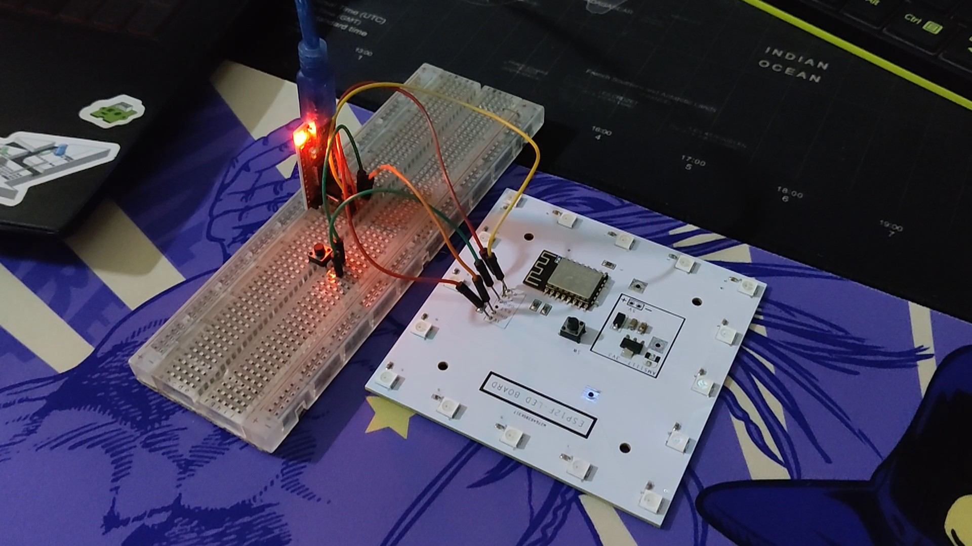
To program the ESP12F module, the usual FTDI board method, which requires connecting a flashing button between GPIO 0 and the GND port, is being used.
We connected the FTDI Board with the ESP Pins according to the below connection.
- TX of ESP to RX of FTDI
- RX of ESP to TX of FTDI
- VCC to 3.3V of ESP
- GND to GND
- GPIO 0 to a push switch; the other pin of Flash button is connected with GND
During uploading, the ESP12F enters programming mode by long-pressing the Flash button first, followed by the reset button.
Here's an article about programming ESP12F with the FTDI Board for more details:
https://www.hackster.io/Arnov_Sharma_makes/esp12f-standalone-circuit-1de4a7
Here's the test sketch.
#define FASTLED_ALLOW_INTERRUPTS 0
#include <FastLED.h>
FASTLED_USING_NAMESPACE

#define DATA_PIN            14
#define NUM_LEDS            16
#define MAX_POWER_MILLIAMPS 500
#define LED_TYPE            WS2812B
#define COLOR_ORDER         GRB

//////////////////////////////////////////////////////////////////////////

CRGB leds[NUM_LEDS];

void setup() {
  delay( 3000); // 3 second delay for boot recovery, and a moment of silence
  FastLED.addLeds<LED_TYPE,DATA_PIN,COLOR_ORDER>(leds, NUM_LEDS)
        .setCorrection( TypicalLEDStrip );
  FastLED.setMaxPowerInVoltsAndMilliamps( 5, MAX_POWER_MILLIAMPS);
}

void loop()
{
  EVERY_N_MILLISECONDS( 20) {
    pacifica_loop();
    FastLED.show();
  }
}

//////////////////////////////////////////////////////////////////////////
//
// The code for this animation is more complicated than other examples, and
// while it is "ready to run", and documented in general, it is probably not
// the best starting point for learning.  Nevertheless, it does illustrate some
// useful techniques.
//
//////////////////////////////////////////////////////////////////////////
//
// In this animation, there are four "layers" of waves of light.
//
// Each layer moves independently, and each is scaled separately.
//
// All four wave layers are added together on top of each other, and then
// another filter is applied that adds "whitecaps" of brightness where the
// waves line up with each other more.  Finally, another pass is taken
// over the led array to 'deepen' (dim) the blues and greens.
//
// The speed and scale and motion each layer varies slowly within independent
// hand-chosen ranges, which is why the code has a lot of low-speed 'beatsin8' functions
// with a lot of oddly specific numeric ranges.
//
// These three custom blue-green color palettes were inspired by the colors found in
// the waters off the southern coast of California, https://goo.gl/maps/QQgd97jjHesHZVxQ7
//
CRGBPalette16 pacifica_palette_1 =
    { 0x000507, 0x000409, 0x00030B, 0x00030D, 0x000210, 0x000212, 0x000114, 0x000117,
      0x000019, 0x00001C, 0x000026, 0x000031, 0x00003B, 0x000046, 0x14554B, 0x28AA50 };
CRGBPalette16 pacifica_palette_2 =
    { 0x000507, 0x000409, 0x00030B, 0x00030D, 0x000210, 0x000212, 0x000114, 0x000117,
      0x000019, 0x00001C, 0x000026, 0x000031, 0x00003B, 0x000046, 0x0C5F52, 0x19BE5F };
CRGBPalette16 pacifica_palette_3 =
    { 0x000208, 0x00030E, 0x000514, 0x00061A, 0x000820, 0x000927, 0x000B2D, 0x000C33,
      0x000E39, 0x001040, 0x001450, 0x001860, 0x001C70, 0x002080, 0x1040BF, 0x2060FF };


void pacifica_loop()
{
  // Increment the four "color index start" counters, one for each wave layer.
  // Each is incremented at a different speed, and the speeds vary over time.
  static uint16_t sCIStart1, sCIStart2, sCIStart3, sCIStart4;
  static uint32_t sLastms = 0;
  uint32_t ms = GET_MILLIS();
  uint32_t deltams = ms - sLastms;
  sLastms = ms;
  uint16_t speedfactor1 = beatsin16(3, 179, 269);
  uint16_t speedfactor2 = beatsin16(4, 179, 269);
  uint32_t deltams1 = (deltams * speedfactor1) / 256;
  uint32_t deltams2 = (deltams * speedfactor2) / 256;
  uint32_t deltams21 = (deltams1 + deltams2) / 2;
  sCIStart1 += (deltams1 * beatsin88(1011,10,13));
  sCIStart2 -= (deltams21 * beatsin88(777,8,11));
  sCIStart3 -= (deltams1 * beatsin88(501,5,7));
  sCIStart4 -= (deltams2 * beatsin88(257,4,6));

  // Clear out the LED array to a dim background blue-green
  fill_solid( leds, NUM_LEDS, CRGB( 2, 6, 10));

  // Render each of four layers, with different scales and speeds, that vary over time
  pacifica_one_layer( pacifica_palette_1, sCIStart1, beatsin16( 3, 11 * 256, 14 * 256), beatsin8( 10, 70, 130), 0-beat16( 301) );
  pacifica_one_layer( pacifica_palette_2, sCIStart2, beatsin16( 4,  6 * 256,  9 * 256), beatsin8( 17, 40,  80), beat16( 401) );
  pacifica_one_layer( pacifica_palette_3, sCIStart3, 6 * 256, beatsin8( 9, 10,38), 0-beat16(503));
  pacifica_one_layer( pacifica_palette_3, sCIStart4, 5 * 256, beatsin8( 8, 10,28), beat16(601));

  // Add brighter 'whitecaps' where the waves lines up more
  pacifica_add_whitecaps();

  // Deepen the blues and greens a bit
  pacifica_deepen_colors();
}

// Add one layer of waves into the led array
void pacifica_one_layer( CRGBPalette16& p, uint16_t cistart, uint16_t wavescale, uint8_t bri, uint16_t ioff)
{
  uint16_t ci = cistart;
  uint16_t waveangle = ioff;
  uint16_t wavescale_half = (wavescale / 2) + 20;
  for( uint16_t i = 0; i < NUM_LEDS; i++) {
    waveangle += 250;
    uint16_t s16 = sin16( waveangle ) + 32768;
    uint16_t cs = scale16( s16 , wavescale_half ) + wavescale_half;
    ci += cs;
    uint16_t sindex16 = sin16( ci) + 32768;
    uint8_t sindex8 = scale16( sindex16, 240);
    CRGB c = ColorFromPalette( p, sindex8, bri, LINEARBLEND);
    leds[i] += c;
  }
}

// Add extra 'white' to areas where the four layers of light have lined up brightly
void pacifica_add_whitecaps()
{
  uint8_t basethreshold = beatsin8( 9, 55, 65);
  uint8_t wave = beat8( 7 );

  for( uint16_t i = 0; i < NUM_LEDS; i++) {
    uint8_t threshold = scale8( sin8( wave), 20) + basethreshold;
    wave += 7;
    uint8_t l = leds[i].getAverageLight();
    if( l > threshold) {
      uint8_t overage = l - threshold;
      uint8_t overage2 = qadd8( overage, overage);
      leds[i] += CRGB( overage, overage2, qadd8( overage2, overage2));
    }
  }
}

// Deepen the blues and greens
void pacifica_deepen_colors()
{
  for( uint16_t i = 0; i < NUM_LEDS; i++) {
    leds[i].blue = scale8( leds[i].blue,  145);
    leds[i].green= scale8( leds[i].green, 200);
    leds[i] |= CRGB( 2, 5, 7);
  }
}
This is an example sketch from the Fast LED Library, which you need to download and install first before uploading this sketch.
-
3Main Sketch
![]()
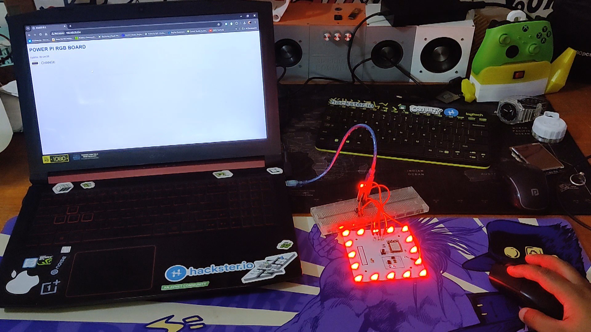
Using the same FTDI technique, we uploaded the main sketch onto the ESP8266 board after making sure the LEDs were working.
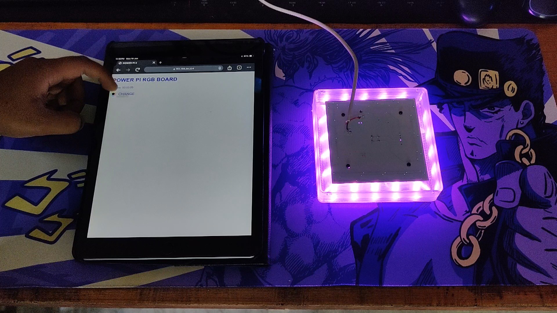
The primary sketch is a WEBSERVER sketch that allows the user to customize the LED board color by choosing from a broad color palette.
#include <Adafruit_NeoPixel.h>

// ESP8266
#include <ESP8266WiFi.h>
#include <WiFiClient.h>
#include <ESP8266WebServer.h>
#include <ESP8266mDNS.h>

// Webserver Config
const char *ssid = "UR SSID";
const char *password = "UR PASS";
ESP8266WebServer server ( 80 );

// Neopixel Config
#define NeoPIN 14 //GPIOI12
#define NUM_LEDS 16 //define number of leds in your strip, mine is 18
int brightness = 250;
Adafruit_NeoPixel strip = Adafruit_NeoPixel(NUM_LEDS, NeoPIN, NEO_RGB + NEO_KHZ800);


const int led = 13;

void setup ( void ) {

  Serial.begin ( 115200 );

  // ##############
  // NeoPixel start
  Serial.println();
  strip.setBrightness(brightness);
  strip.begin();
  strip.show();
  delay(50);
  Serial.println("NeoPixel started");

  // #########
  // Webserver
  pinMode ( led, OUTPUT );
  digitalWrite ( led, 0 );

  WiFi.begin ( ssid, password );
  Serial.println ( "" );

  // Wait for connection
  while ( WiFi.status() != WL_CONNECTED ) {
    delay ( 500 );
    Serial.print ( "." );
  }

  Serial.println ( "" );
  Serial.print ( "Connected to " );
  Serial.println ( ssid );
  Serial.print ( "IP address: " );
  Serial.println ( WiFi.localIP() );

  if ( MDNS.begin ( "esp8266" ) ) {
    Serial.println ( "MDNS responder started" );
  }

  // what to do with requests
  server.on ( "/", handleRoot );
  server.onNotFound ( handleNotFound );
  server.begin();


  Serial.println ( "HTTP server started" );
}

void loop ( void ) {
  // waiting fo a client
  server.handleClient();
}


void handleRoot() {
  Serial.println("Client connected");
  digitalWrite ( led, 1 );

  // data from the colorpicker (e.g. #FF00FF)
  String color = server.arg("c");
  Serial.println("Color: " + color);
  // setting the color to the strip
  setNeoColor(color);

  // building a website
  char temp[5000];
  int sec = millis() / 1000;
  int min = sec / 60;
  int hr = min / 60;
  char clr [7];
  color.toCharArray(clr, 7);
  snprintf ( temp, 5000,

"<!DOCTYPE html>\n<html>\n\
  <head>\n\
    <title>POWER PI 2</title>\n\
    <style>\
      body { background-color: #cccccc; font-family: Arial; Color: #008; }\
    </style>\n\
    <meta name=\"viewport\" content=\"width=device-width, height=device-height, initial-scale=1.0, user-scalable=0, minimum-scale=1.0, maximum-scale=1.0\" />\n\
  </head>\n\
  <body>\n\
    <h1>POWER PI RGB BOARD</h1>\n\
    <p>Uptime: %02d:%02d:%02d</p>\n\
    \n\
    <form action=\"\" name=\"pick\" method=\"post\">\n\
    <input type=\"color\" name=\"c\" value=\"%02d\" onchange=\"document.forms['pick'].submit();\" />\n\
     <span onclick=\"document.forms['pick'].submit();\" style=\"font-size:16pt;\"> CHANGE </span>\n\
    </form>\n\
    \n\
  </body>\
</html>",

    hr, min % 60, sec % 60, clr
  );
  server.send ( 200, "text/html", temp );
  digitalWrite ( led, 0 );
}

void handleNotFound() {
  digitalWrite ( led, 1 );
  String message = "File Not Found\n\n";
  message += "URI: ";
  message += server.uri();
  message += "\nMethod: ";
  message += ( server.method() == HTTP_GET ) ? "GET" : "POST";
  message += "\nArguments: ";
  message += server.args();
  message += "\n";

  for ( uint8_t i = 0; i < server.args(); i++ ) {
    message += " " + server.argName ( i ) + ": " + server.arg ( i ) + "\n";
  }

  server.send ( 404, "text/plain", message );
  digitalWrite ( led, 0 );
}


void setNeoColor(String value){
  Serial.print("Setting Neopixel...");
  // converting Hex to Int
  int number = (int) strtol( &value[1], NULL, 16);

  // splitting into three parts
  int r = number >> 16;
  int g = number >> 8 & 0xFF;
  int b = number & 0xFF;

  // DEBUG
  Serial.print("RGB: ");
  Serial.print(r, DEC);
  Serial.print(" ");
  Serial.print(g, DEC);
  Serial.print(" ");
  Serial.print(b, DEC);
  Serial.println(" ");

  // setting whole strip to the given color
  for(int i=0; i < NUM_LEDS; i++) {
    strip.setPixelColor(i, strip.Color( g, r, b ) );
  }
  // init
  strip.show();

  Serial.println("on.");
}
Here's how this works: after uploading the sketch, we go to the serial monitor and wait for the ESP to connect with the Wi-Fi router.
Next, we copy the IP address and input it into a browser that opens the web app.
The web app lets users pick any color from the color palette provided.
-
4Main Body Assembly
![]()
![]()
![]()
![]()
![]()
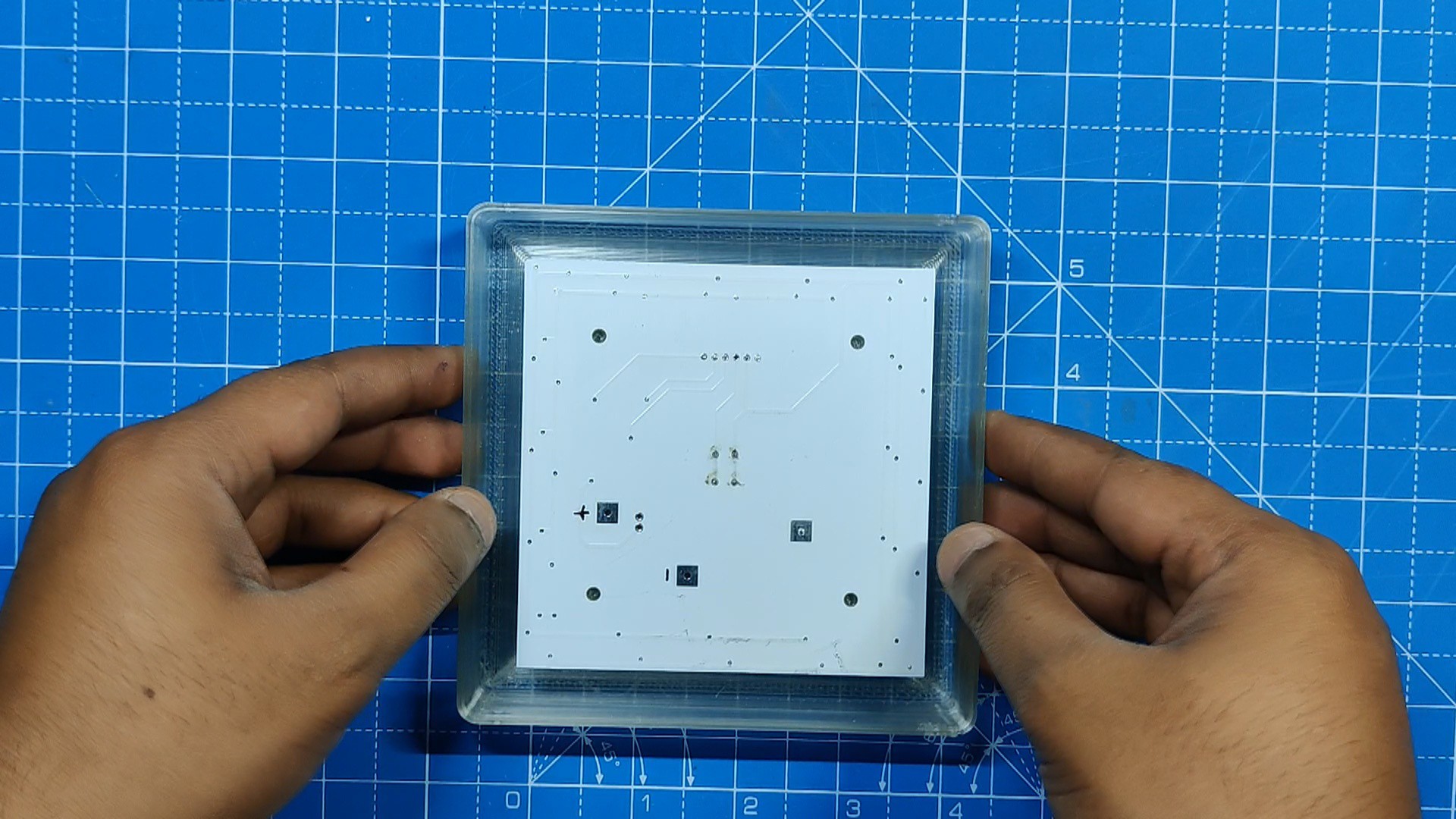
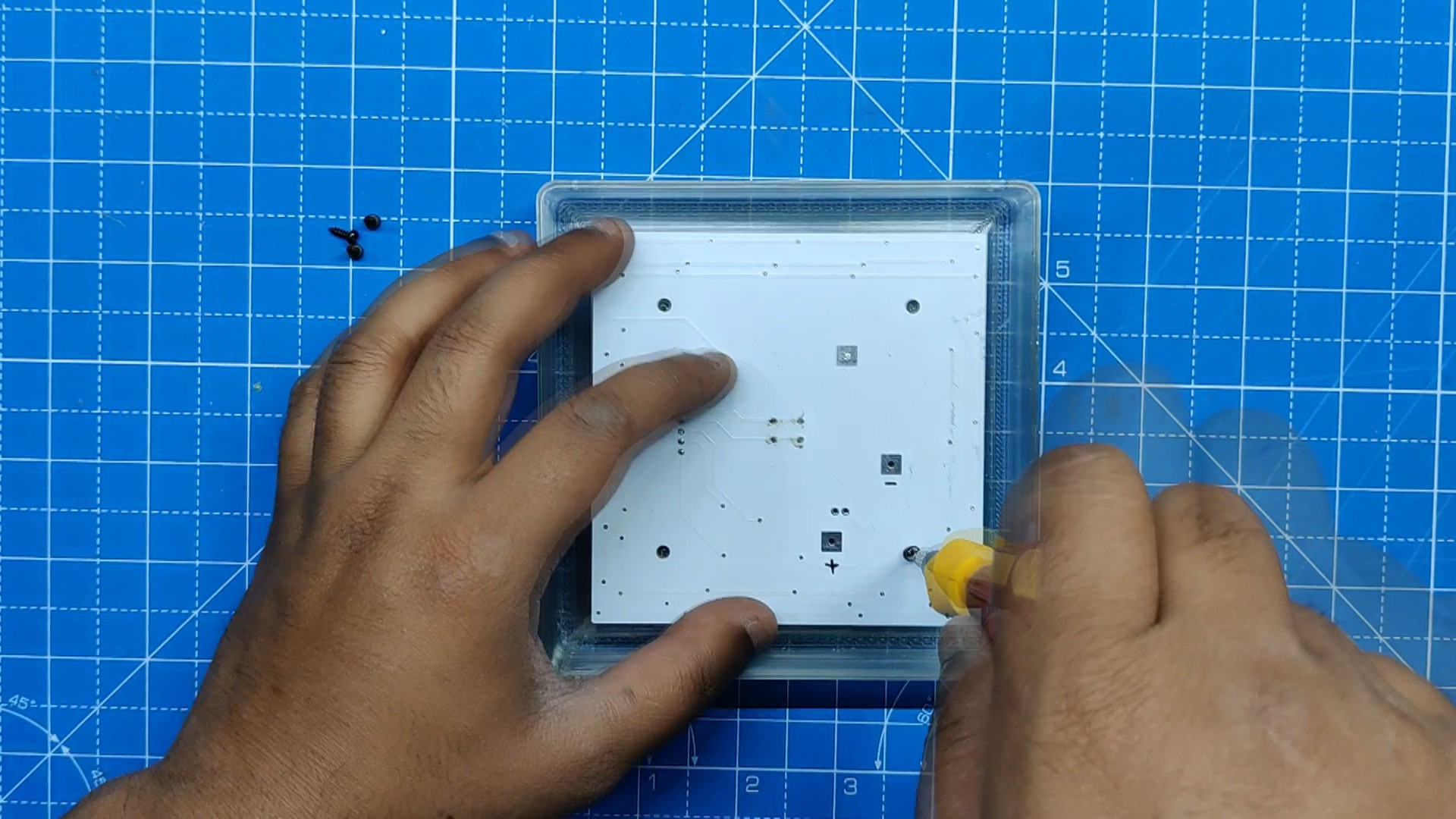
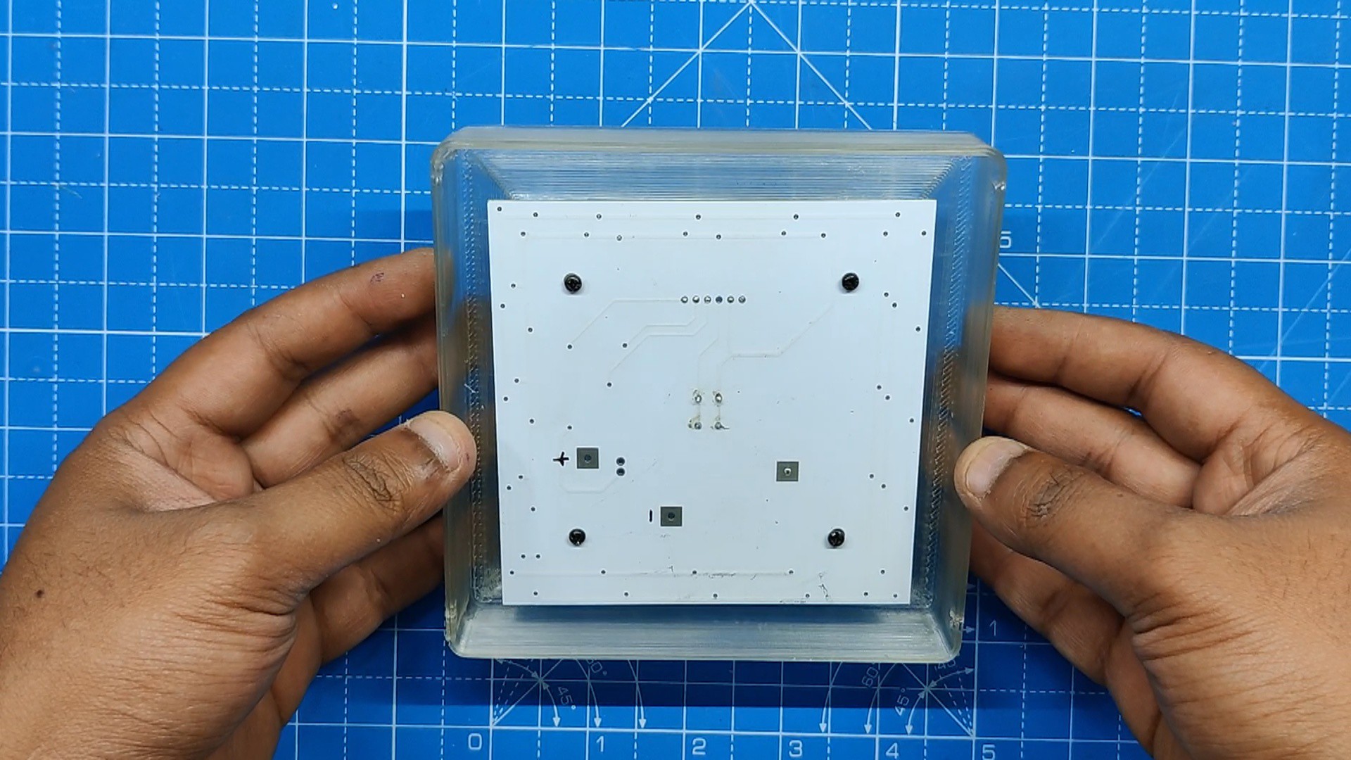
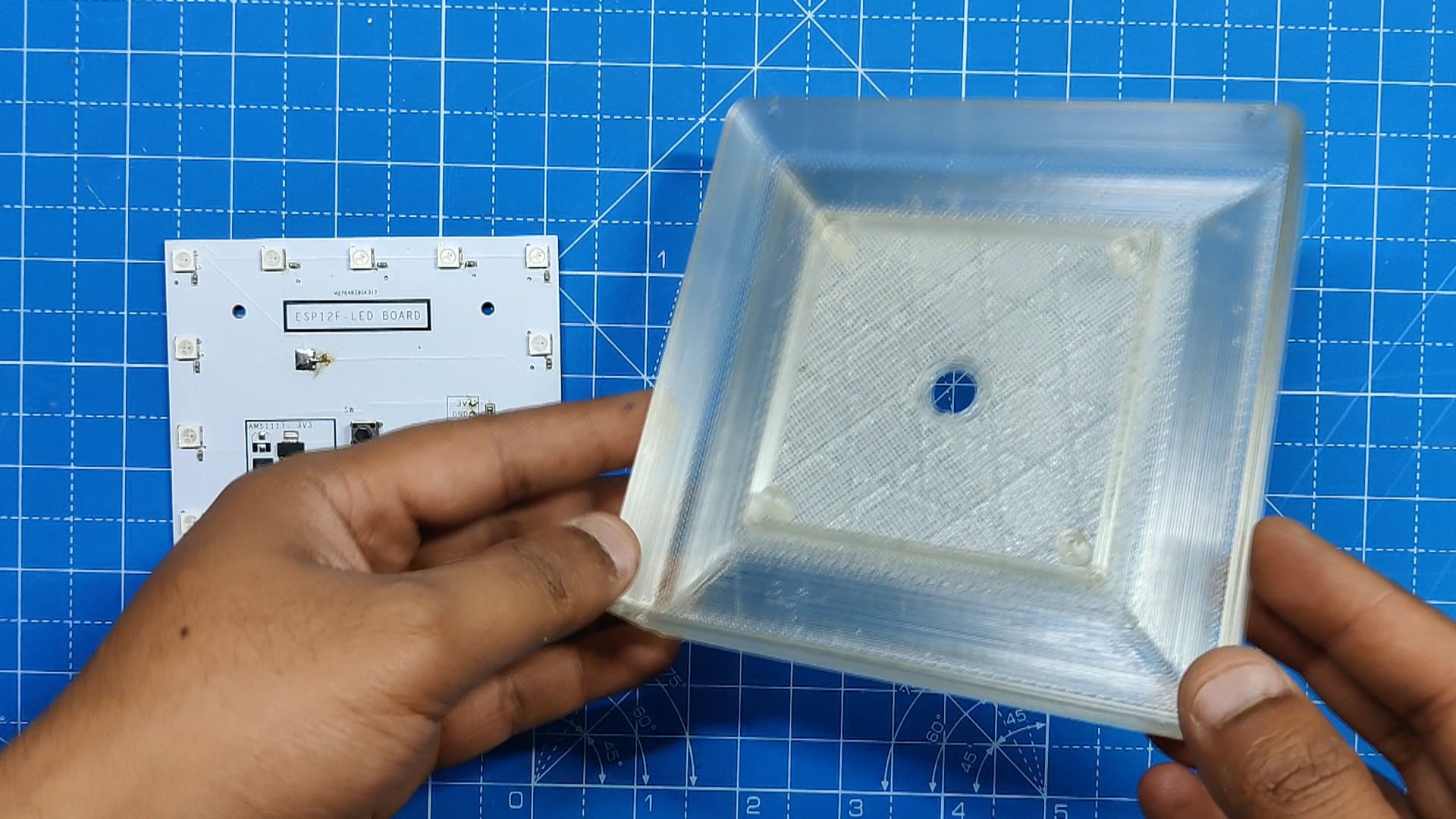
After finalizing the LED board and testing the RGB LEDs, we move onto the final step of this project, which is to assemble the whole setup together.
- The RGB LED Board is positioned on the base's screw bosses with the LEDs facing the inside face of the base.
- Using four M2 screws, we secure the circuit with the 3D-printed base.
- The assembly is finished. Now that the VCC and GND of a USB cable are soldered to the board's 5V and GND ports, testing can begin.
-
5RESULT
![]()
![]()
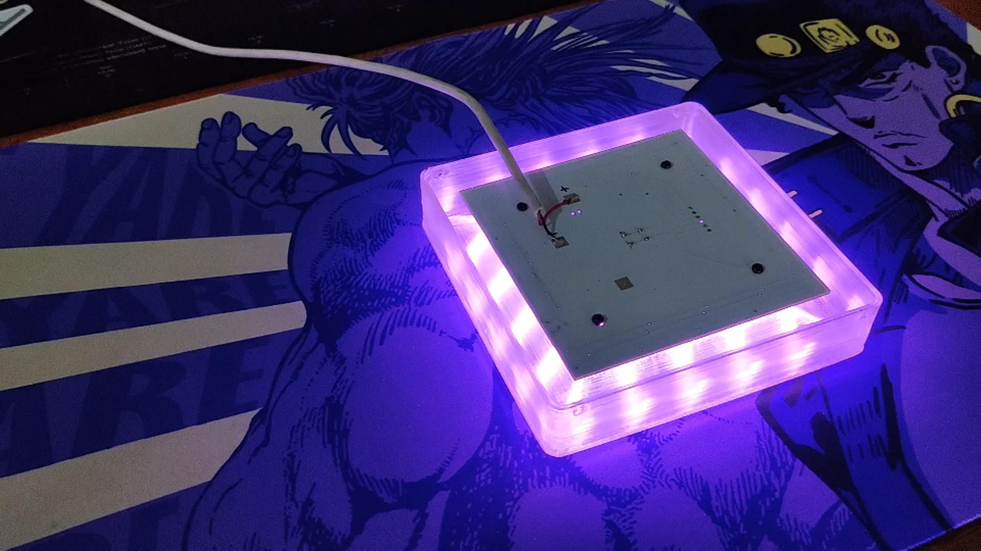
Here's the result of this small build: a functional RGB LED board that can be operated with a straightforward Web app that can be accessed locally with any web browser.
Using the color palette provided in the web app, we can alter the LEDs' color.
The IP address that was found on the serial monitor during ESP Board programming can be entered into the browser to access the web application.
The range of this device is also wide; it can function just like any usual Wi-Fi device.
The transparent body diffuses the LEDs' light, improving and spreading the glow.
-
6What's Next?
![]()
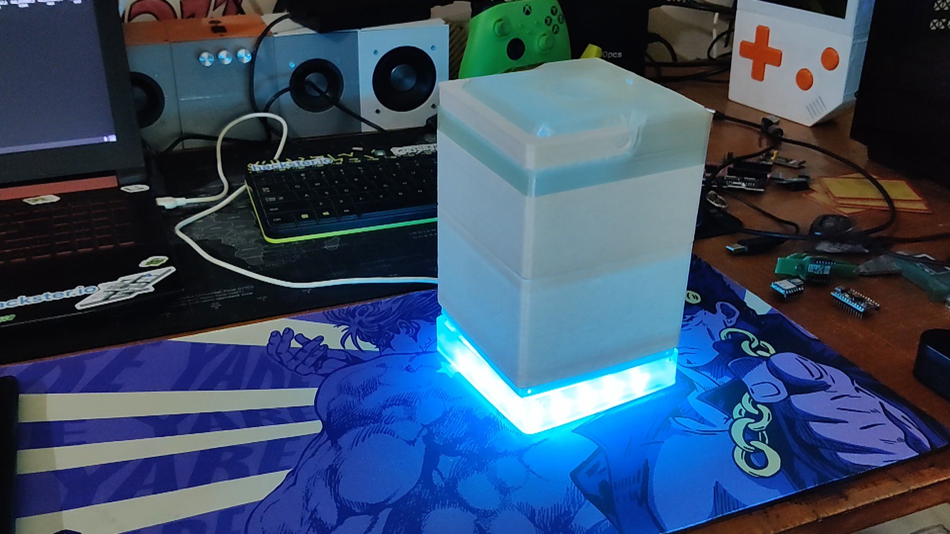
This is a glimpse of the project that will make use of the LED board.
The RGB LED board setup is the base of the project; it contains the RGB LEDs that illuminate the lower portion of the arrangement and give it an overall appealing vibe.
The RGB LED Board, will have a steady 5V power supply from the Power Pi Project in order to function properly.
Overall, this project is complete and needs no further revisions.
A special thank to PCBWAY for supporting this project; visit them to get a wide range of services, including CNC and PCB services.
I will be back with a new project soon.
RGB LED Board for Power Pi 2
LED Board is an ESP8266-based LED driver board for aesthetics, controlled by a web server
Discussions
Become a Hackaday.io Member
Create an account to leave a comment. Already have an account? Log In.