-
1Main Body Assembly
![]()
![]()
![]()
![]()
![]()
![]()
![]()
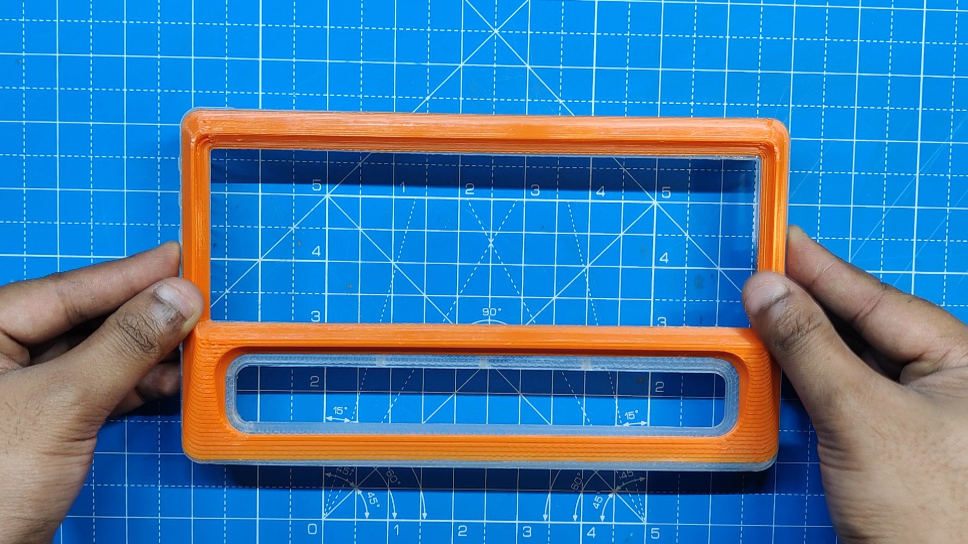
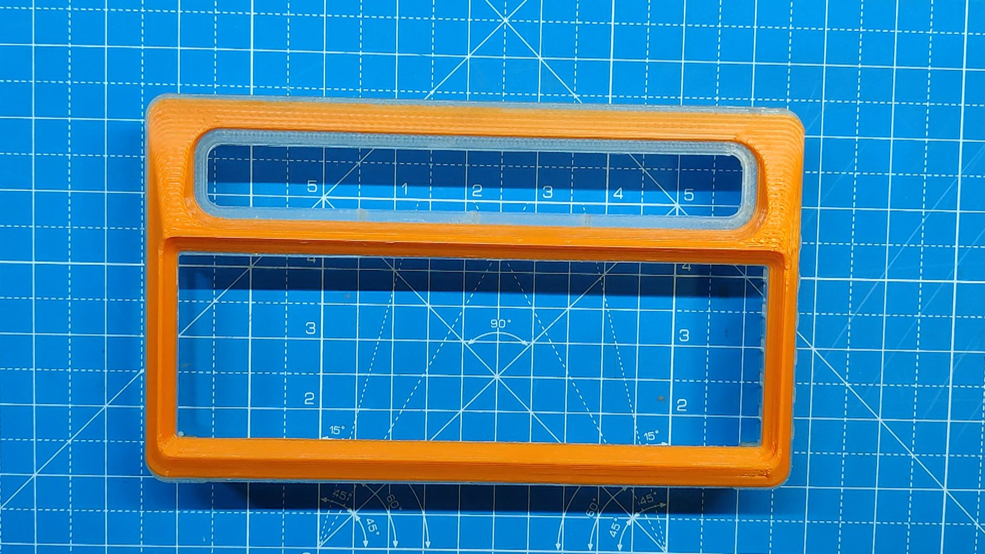
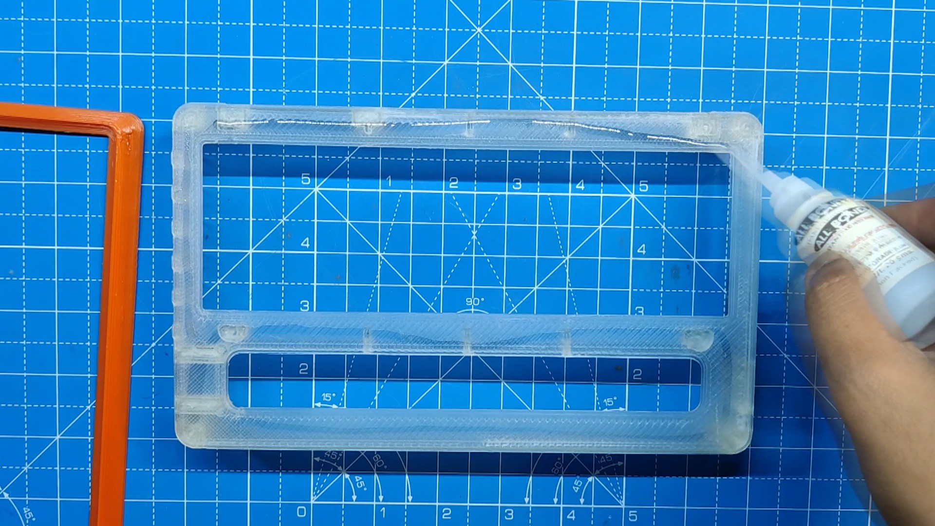
- Super glue is initially applied to the main body, and then the front face is positioned in its proper position to begin the assembly procedure.
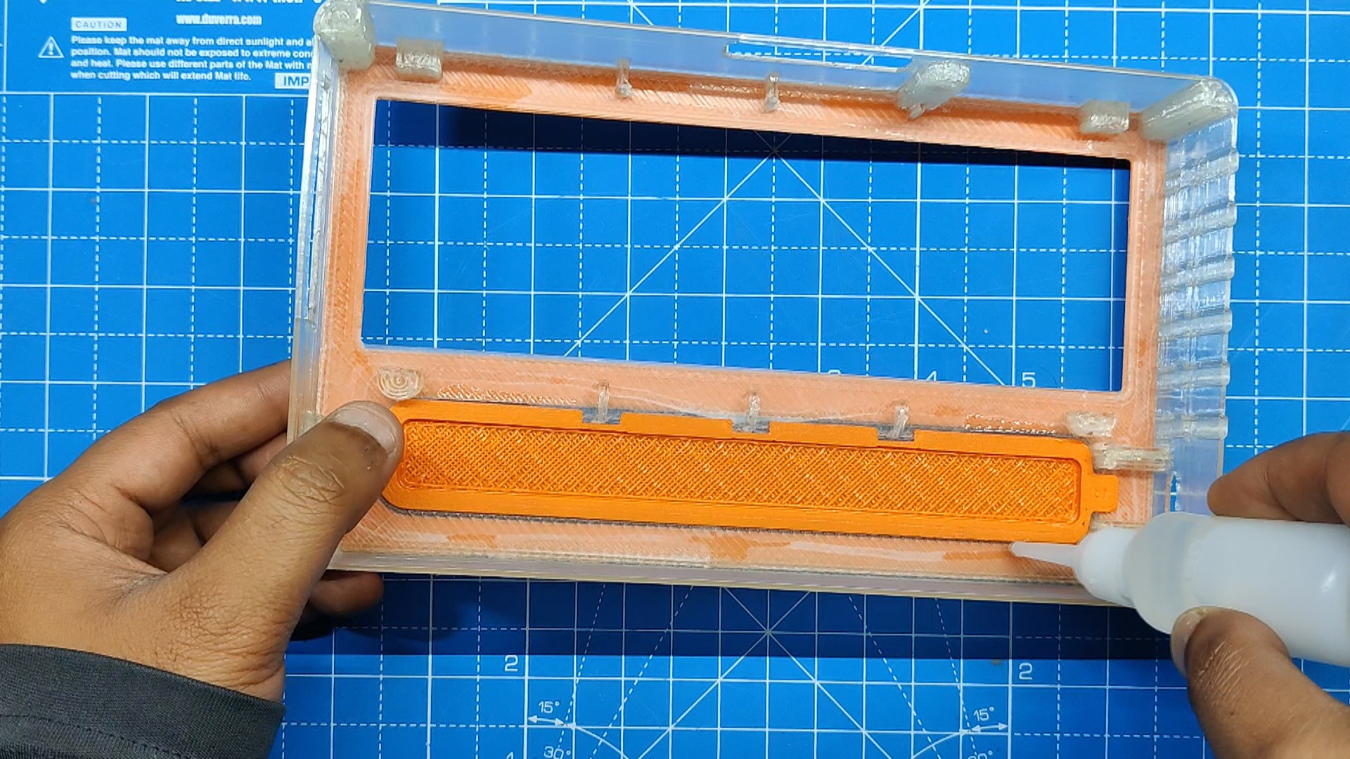
- In a similar manner, we inserted the slot section from the interior of the main body, and it fit properly. Superglue is used to permanently attach it to the main body in order to ensure integrity.
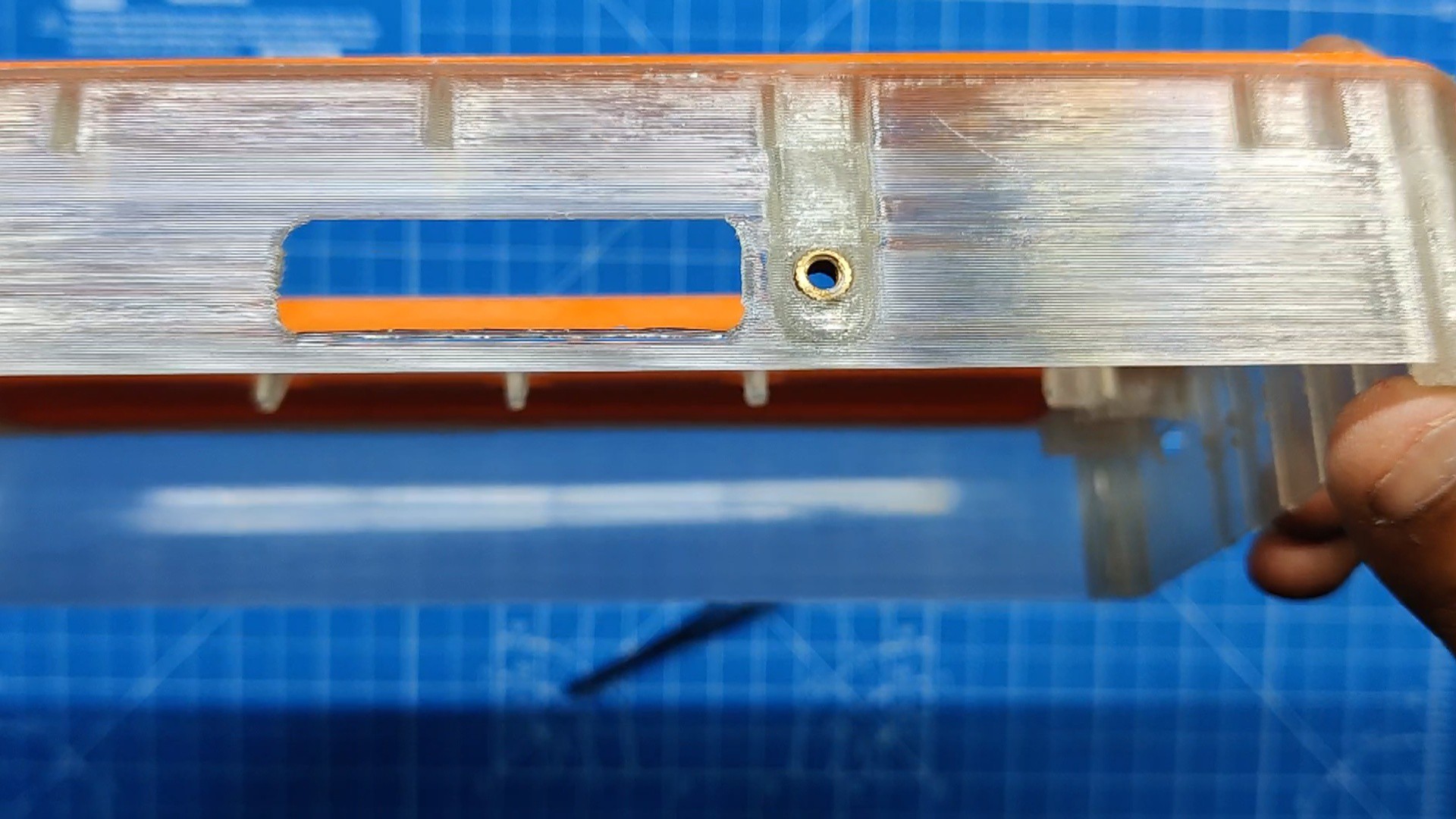
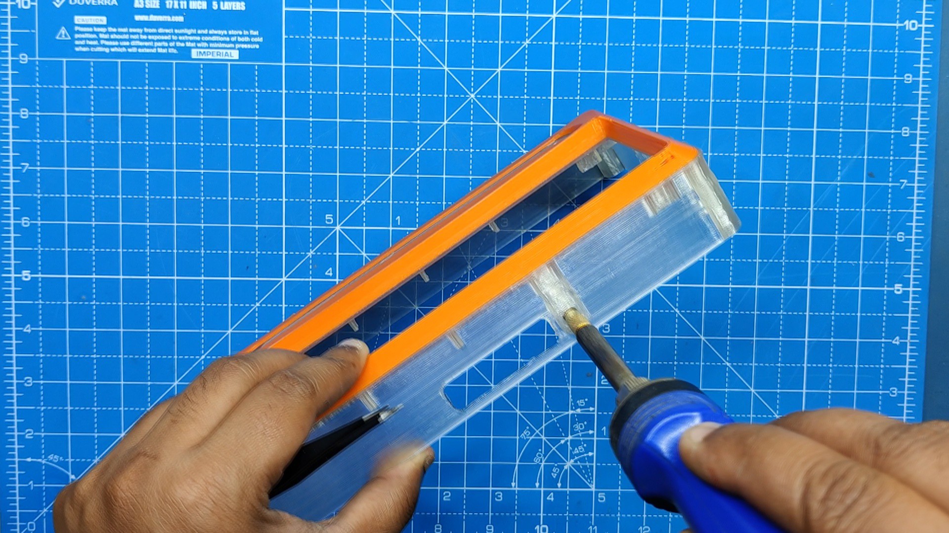
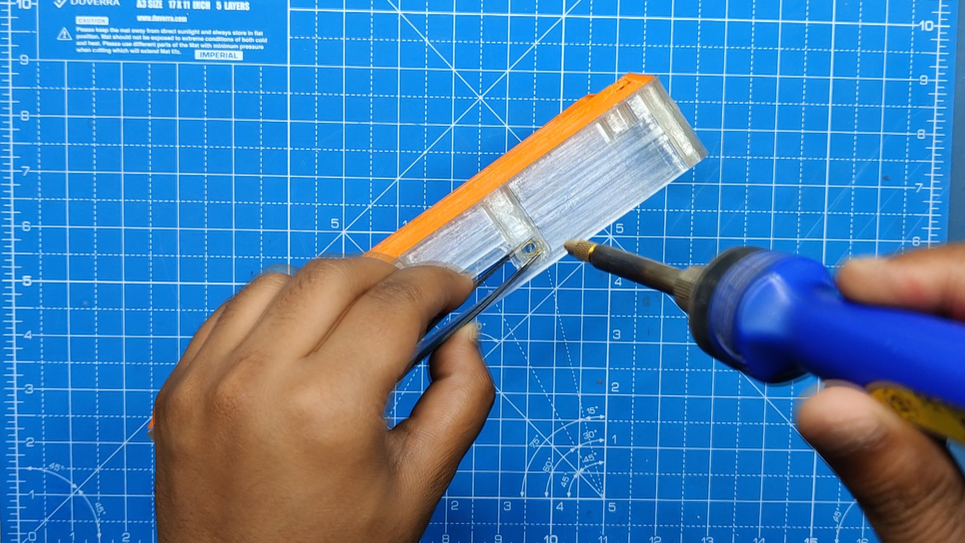
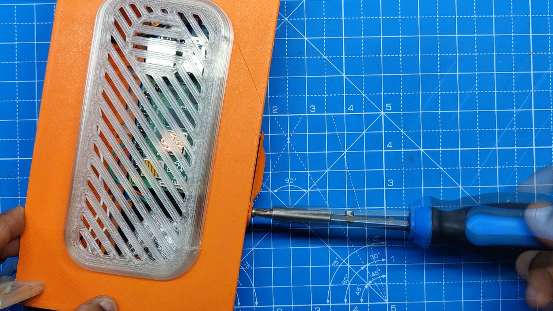
- Next, we added M2.5 screw-threaded inserts into the hole provided on the main body, We used a soldering iron paired with a TS100 TIP Adaptor Kit that we obtained from PCBWAY Giftshop. Using the soldering iron, pick and position the threaded insert over the hole, then push it down until it heats up and slides into place.
- At last, we added the DC Barrel Jack in its place on the main body.
-
2Adding Screen and Pi Assembly with Main Body
![]()
![]()
![]()
![]()
![]()
![]()
![]()
![]()
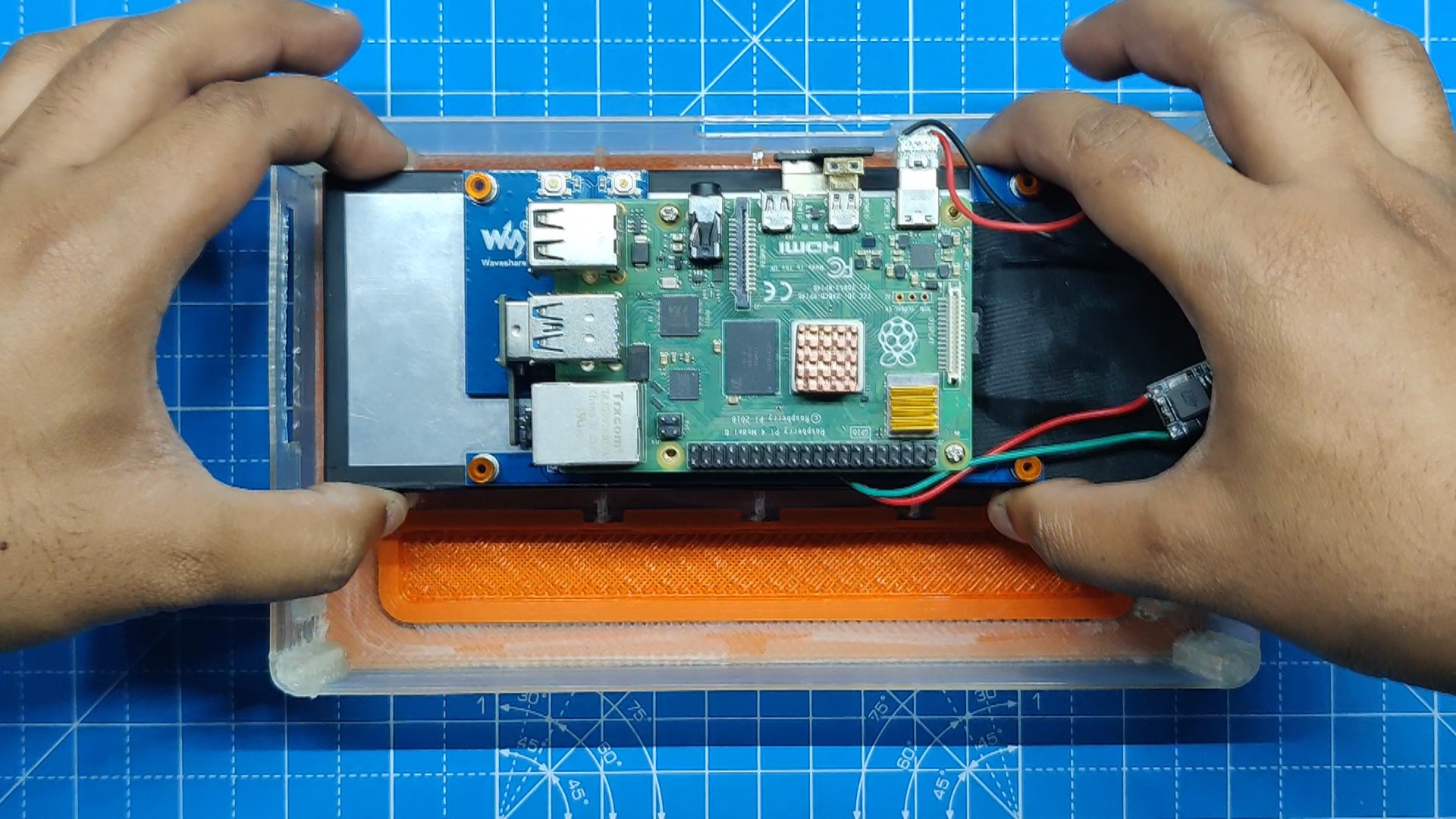
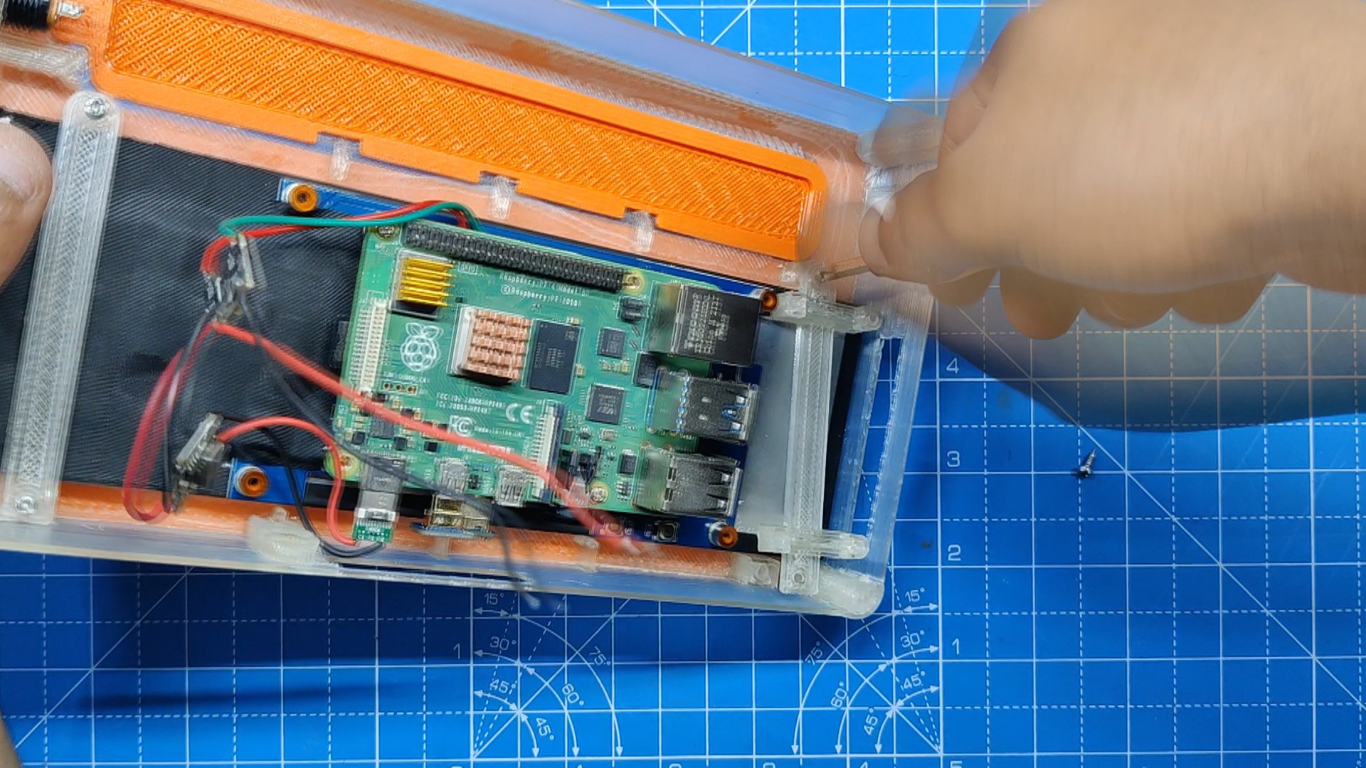
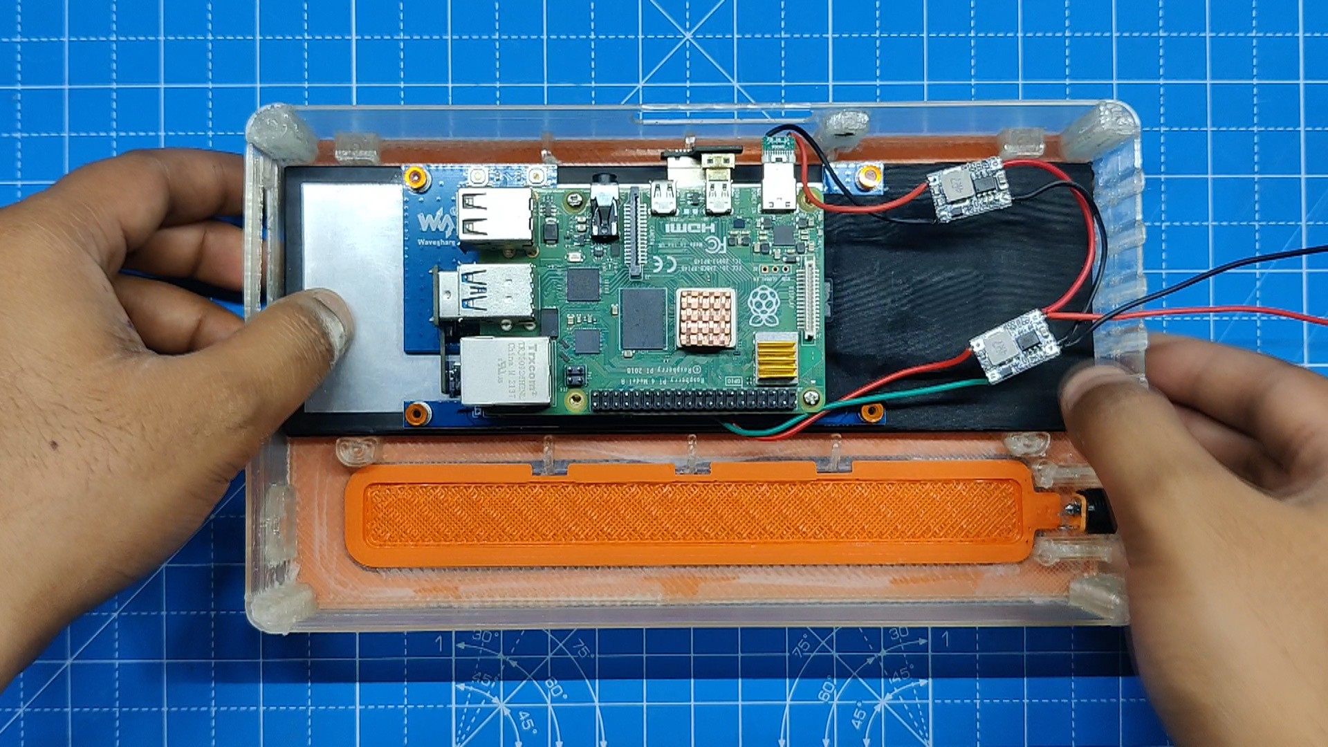
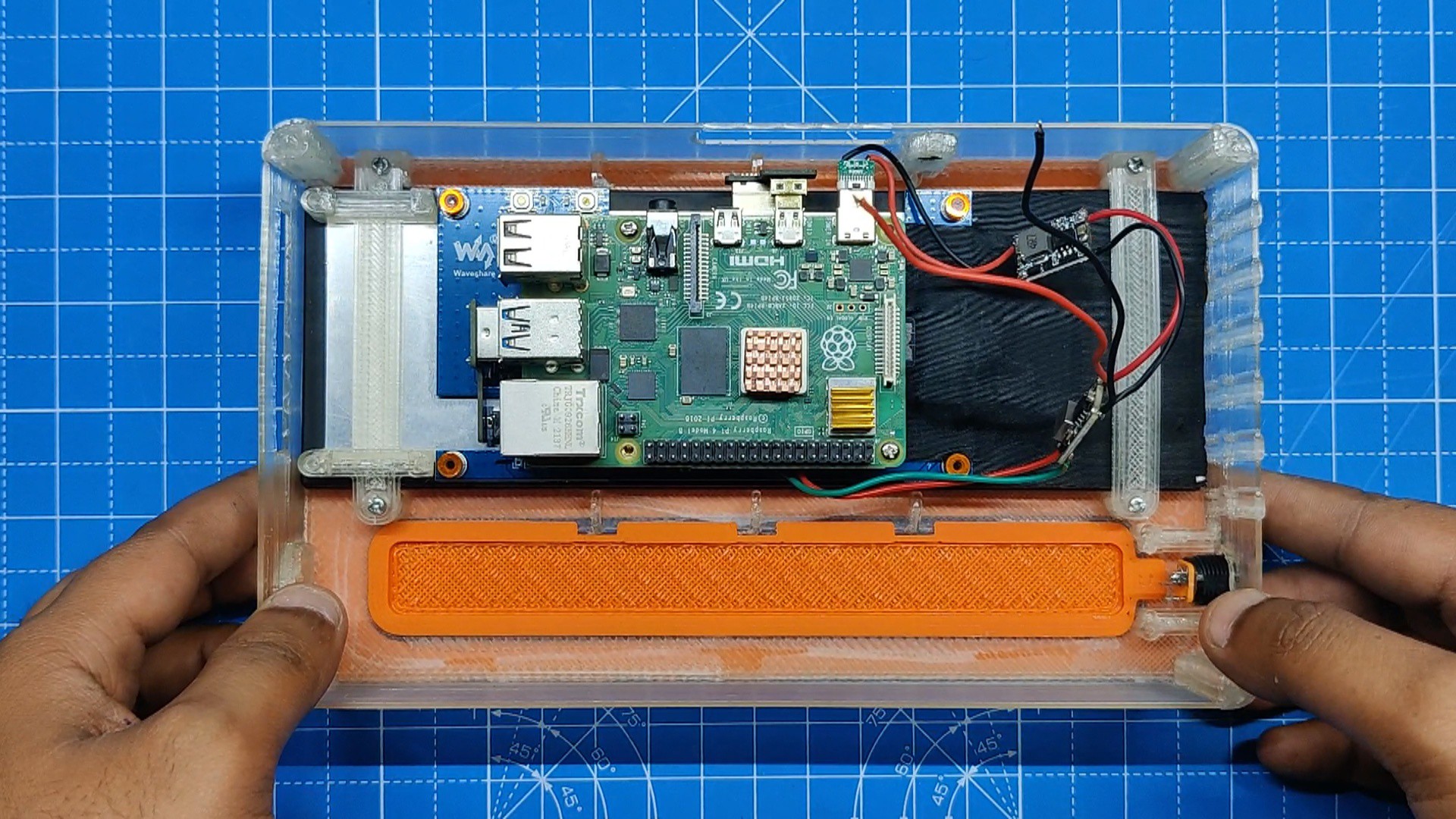
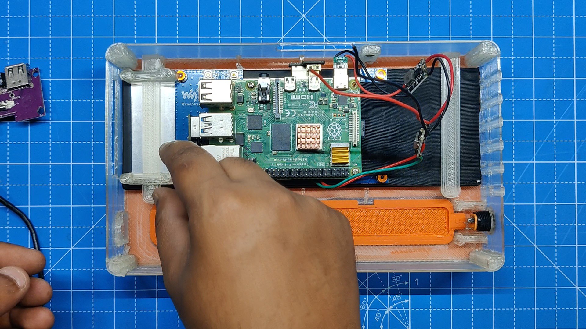
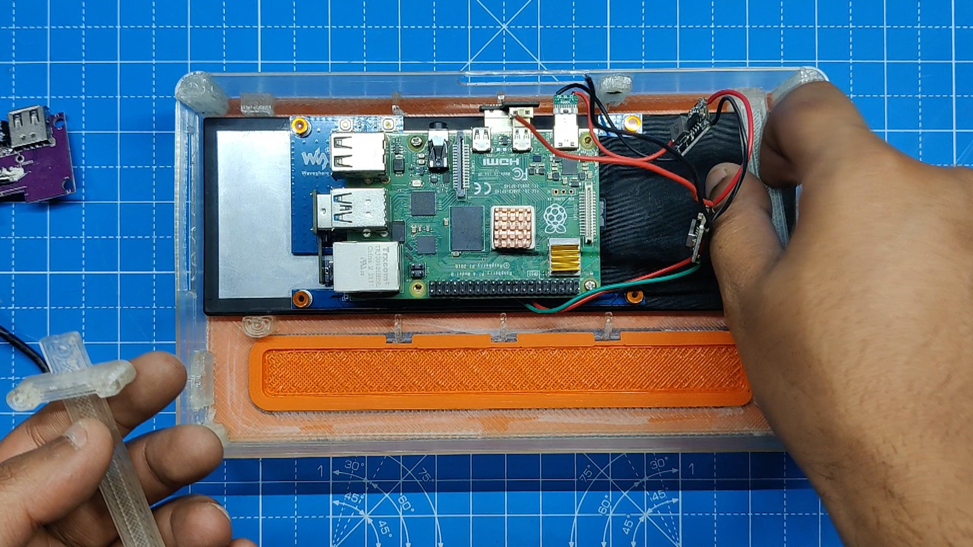
- The Display-Raspberry Pi assembly is now picked up and placed inside the main body's screen location. Supporting ribs are designed all around the display to keep it in place.
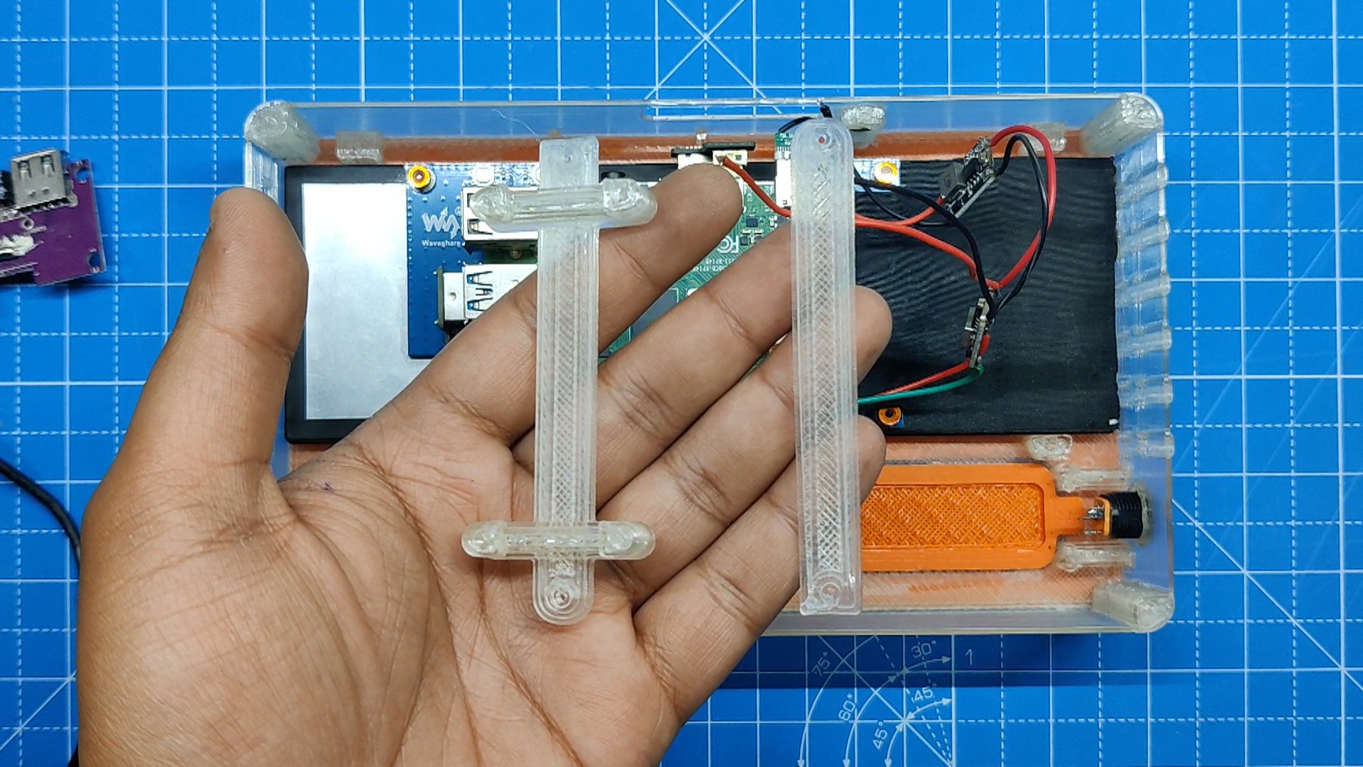
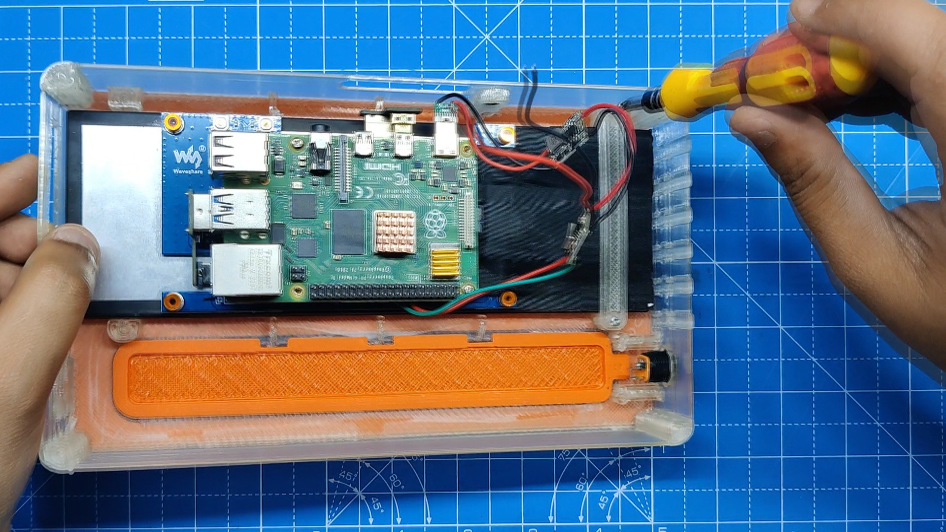
- We use screen holders, which are positioned in their proper locations and then permanently fastened with two M2 screws each, to hold the display in place.
-
3USB Hub Assembly
![]()
![]()
![]()
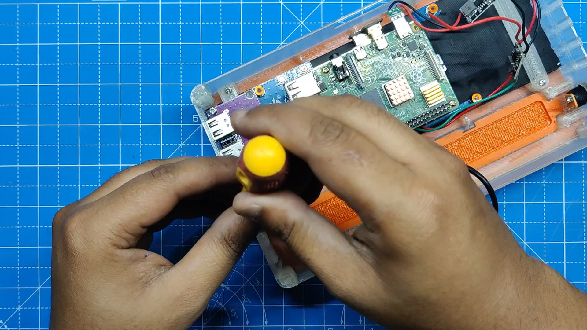
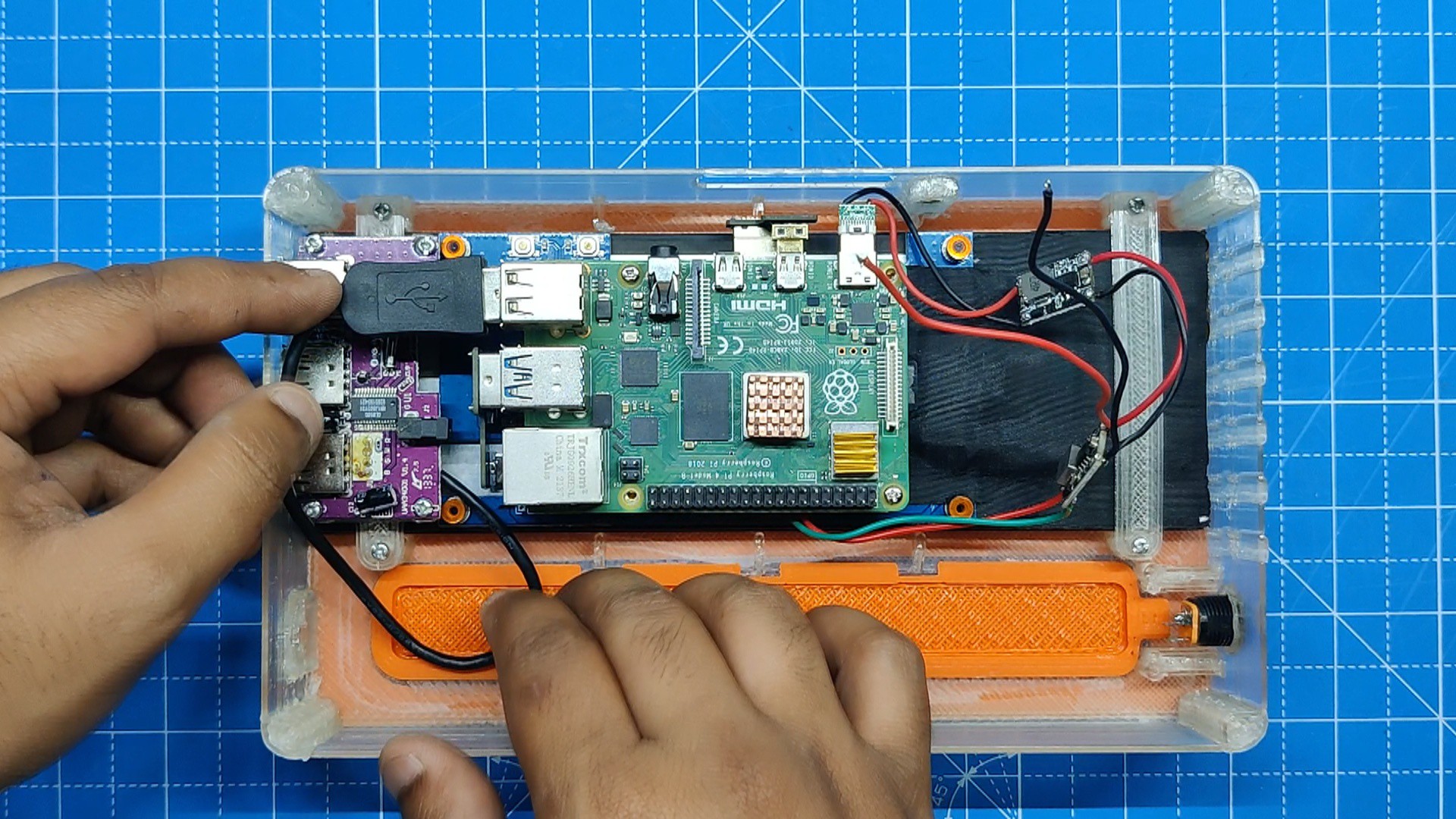
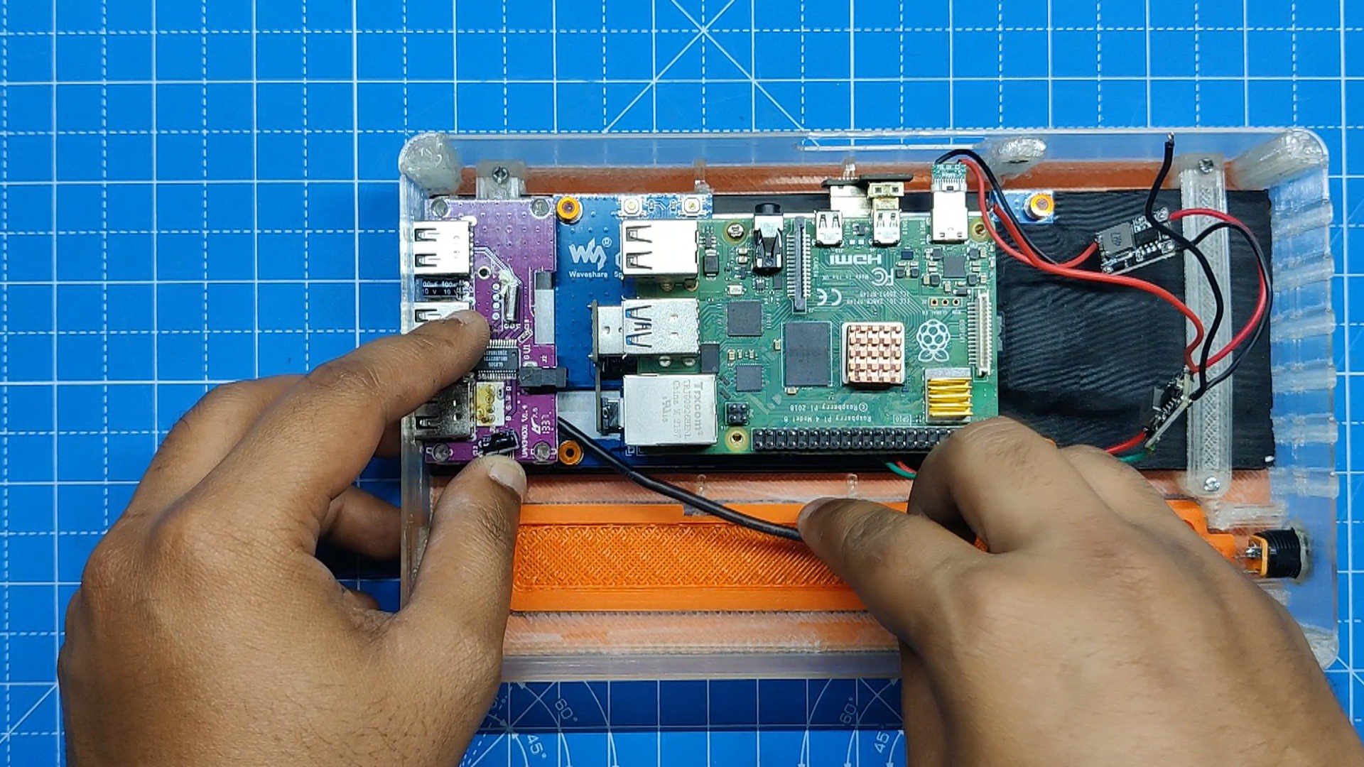
- Using a USB Hub bare circuit that we salvaged from an outdated USB Hub product, we are able to connect a mouse and keyboard to a Raspberry Pi. The hub features three USB 2.0 ports.
- Screen Holder 1 has four mounting holes on it that are used to secure the USB Hub circuit in place when it is positioned over it.
- We then use four M2 screws to secure the USB hub in its place.
- Finally, we connect the Raspberry Pi USB port to the hub's USB cable.
-
4ON-OFF Switch Assembly
![]()
![]()
![]()
![]()
![]()
![]()
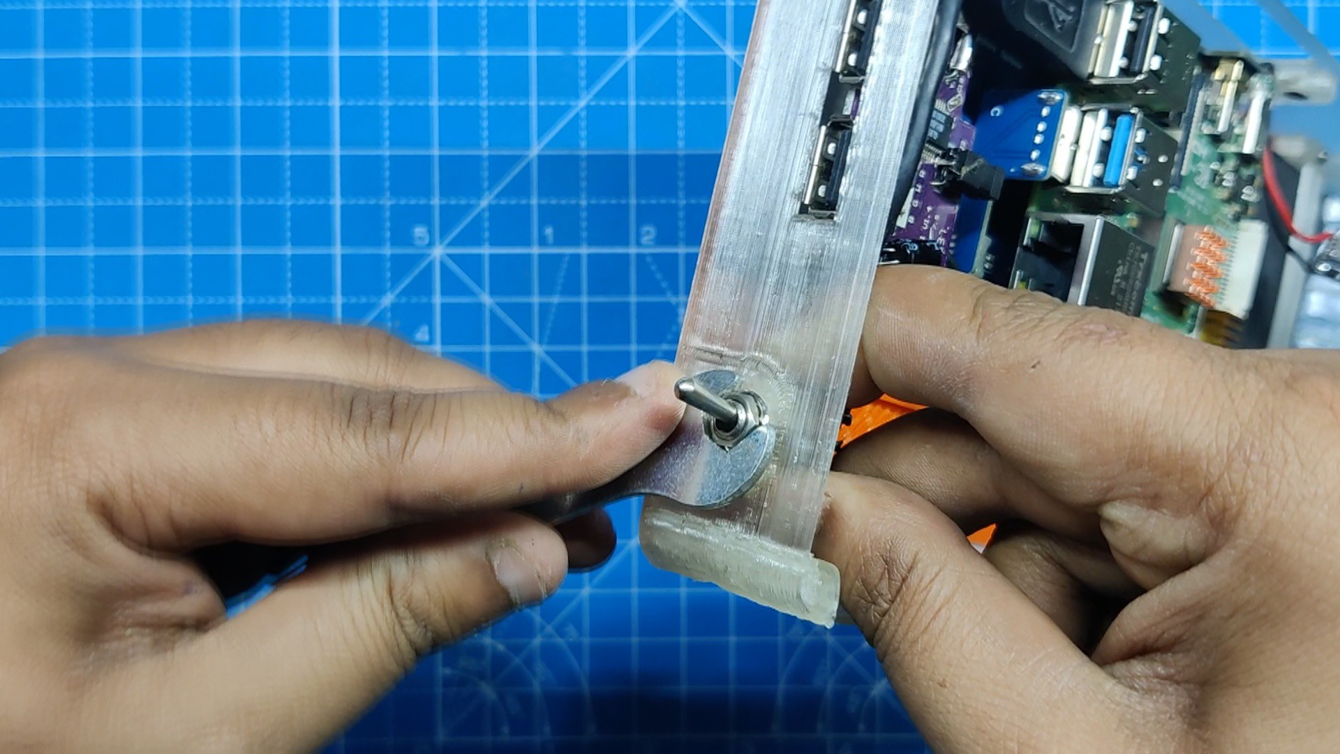
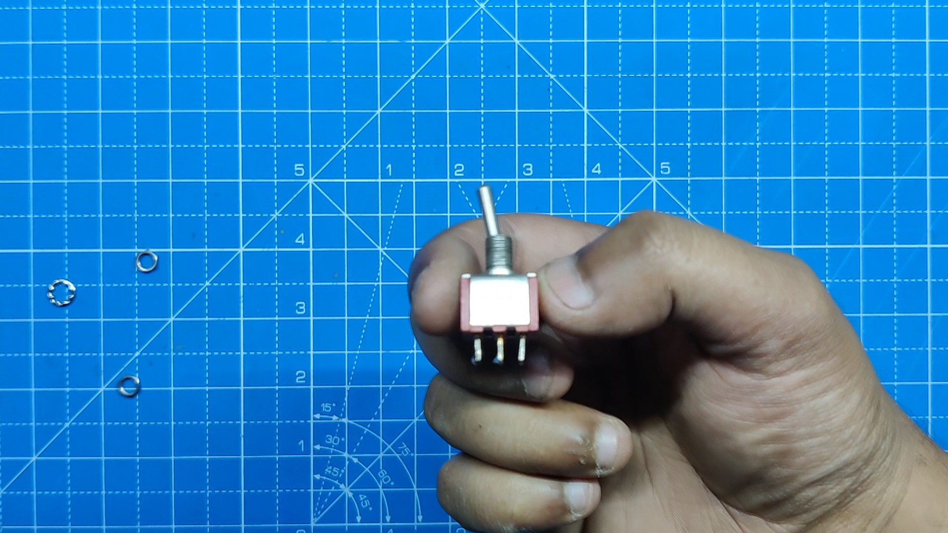
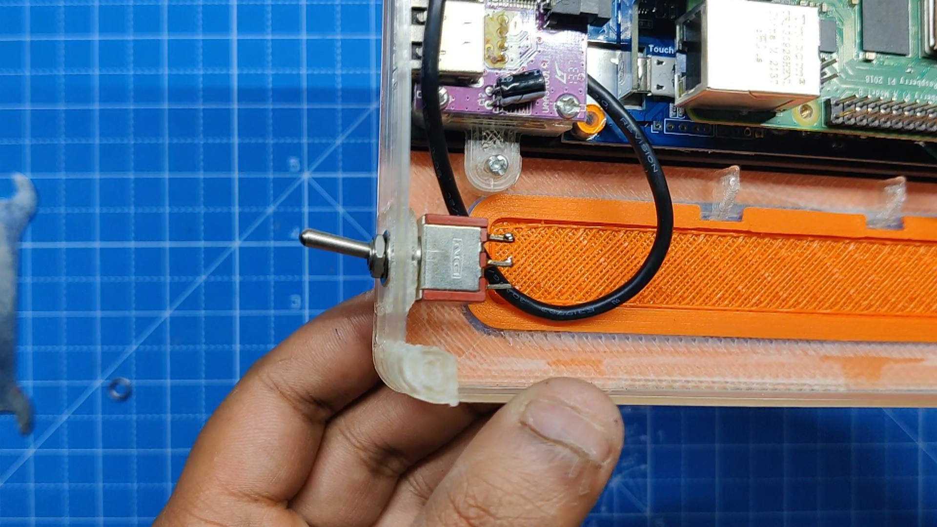
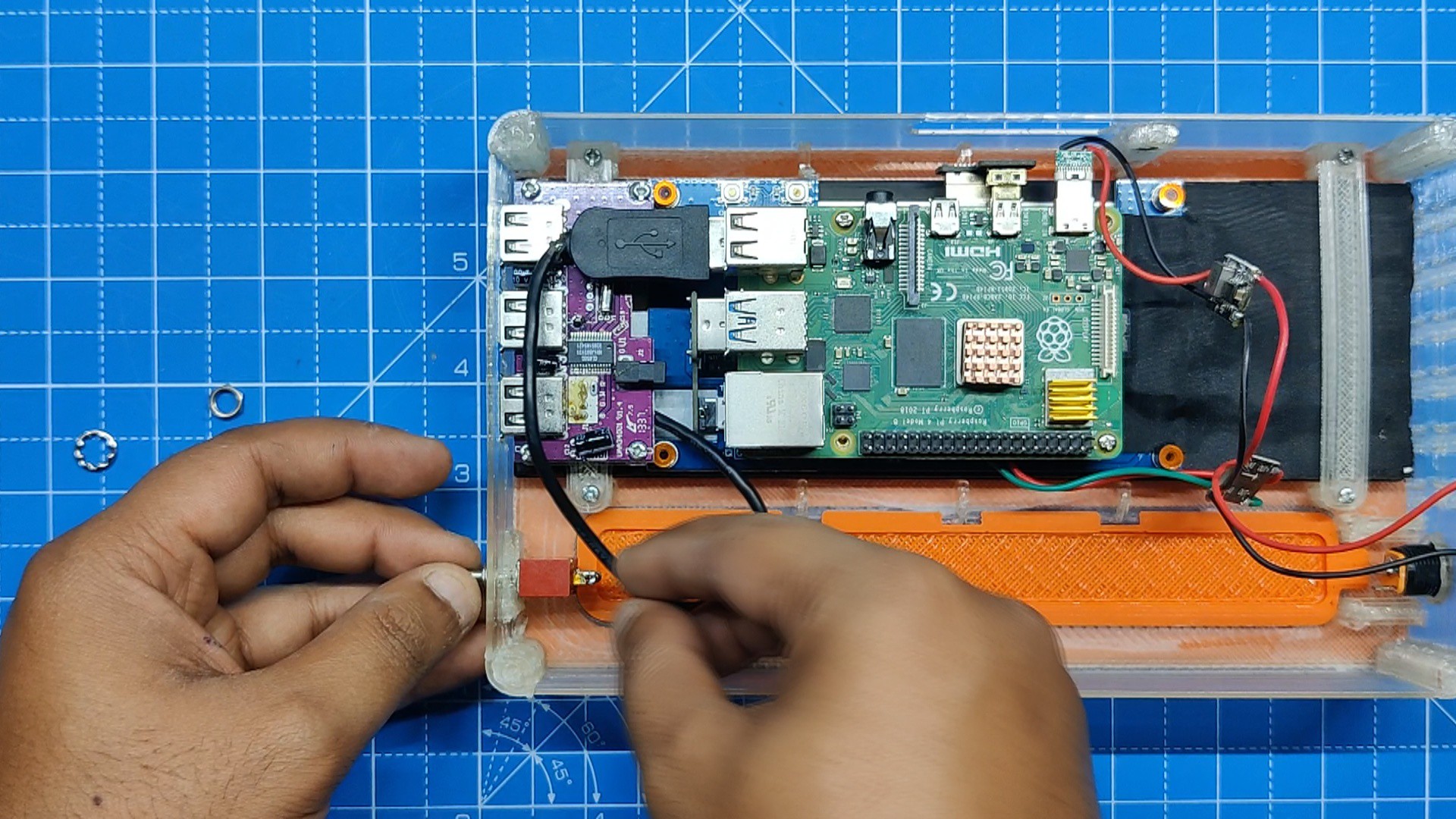
- We installed an SPDT toggle switch on the main body in order to cut off power to the DC DC Modules from the DC barrel jack.
- Previously, we made a circular opening close to the USB slots on the main body. We then placed the switch there and secured it firmly using the toggle switch's M5 nut.
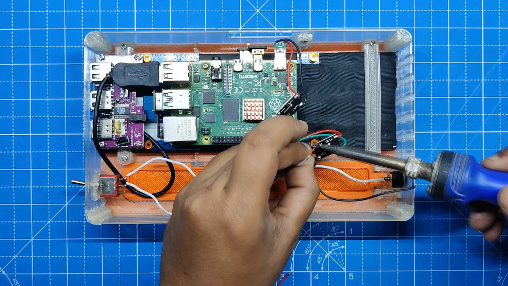
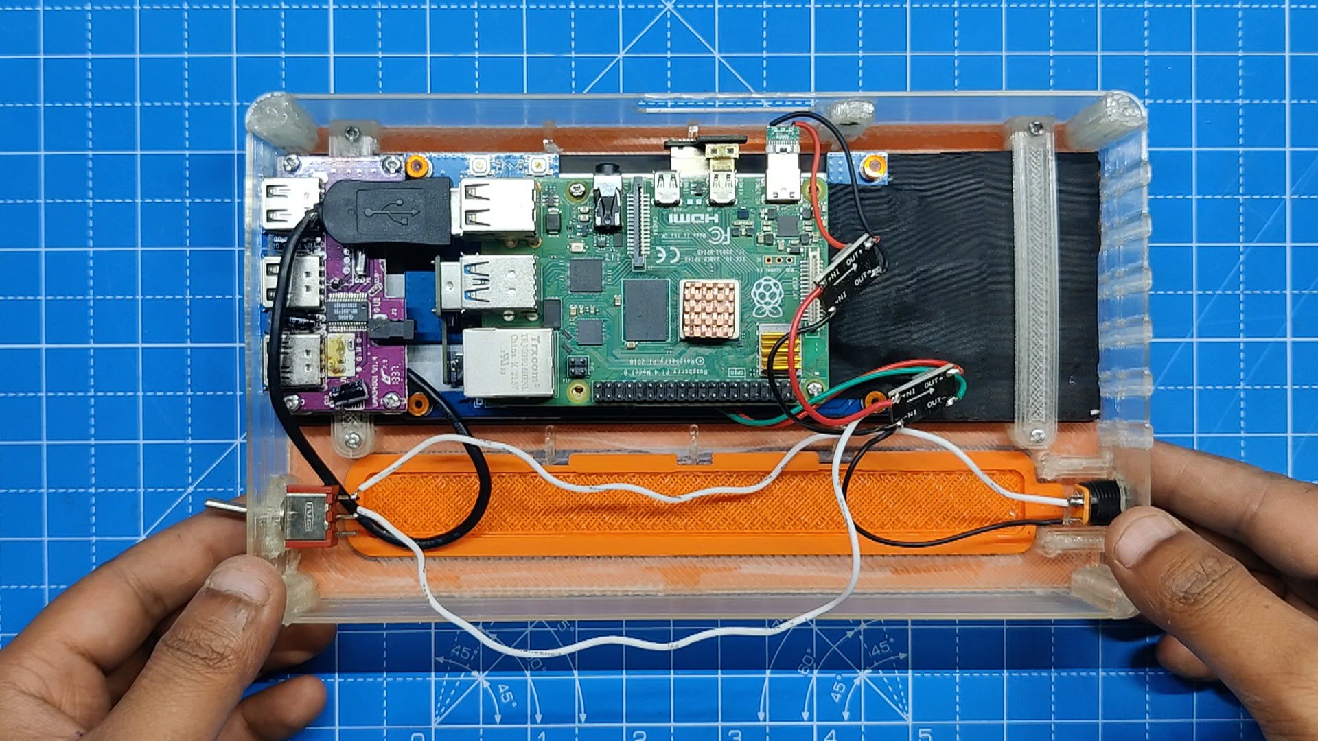
- next, we connect the DC-DC Buck module's GND to DC Jack's GND terminal.
- The positive terminal of the DC jack connects to the switch's NO, and the positive terminal of the DC-DC Buck module is connected to the switch's COM.
-
5Lid Part Assembly
![]()
![]()
![]()
![]()
![]()
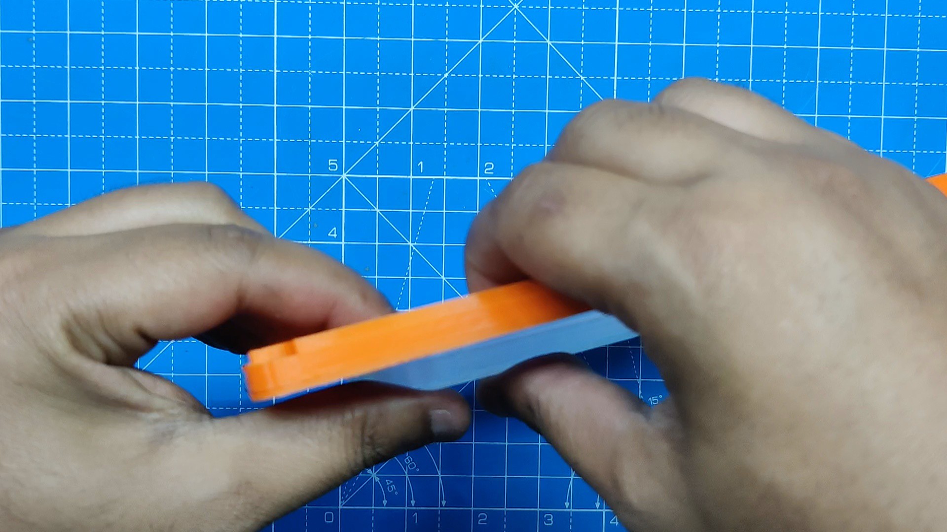
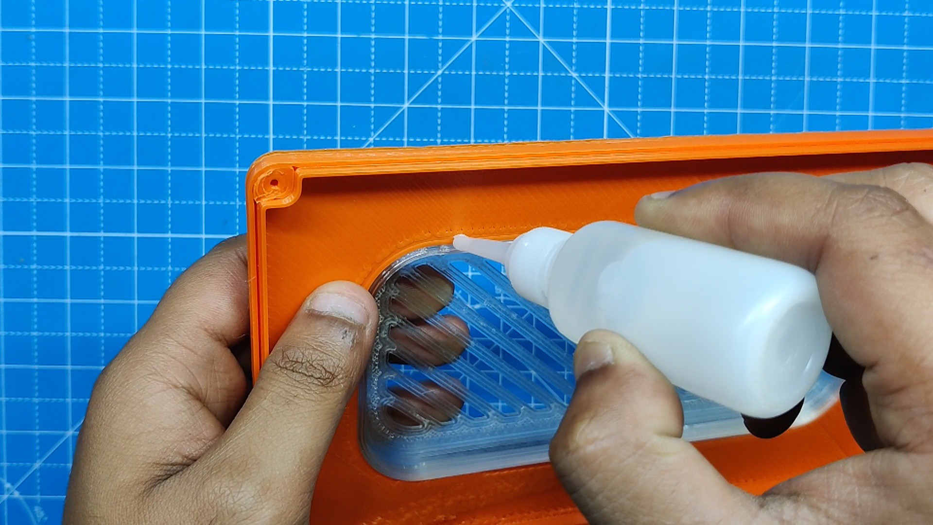
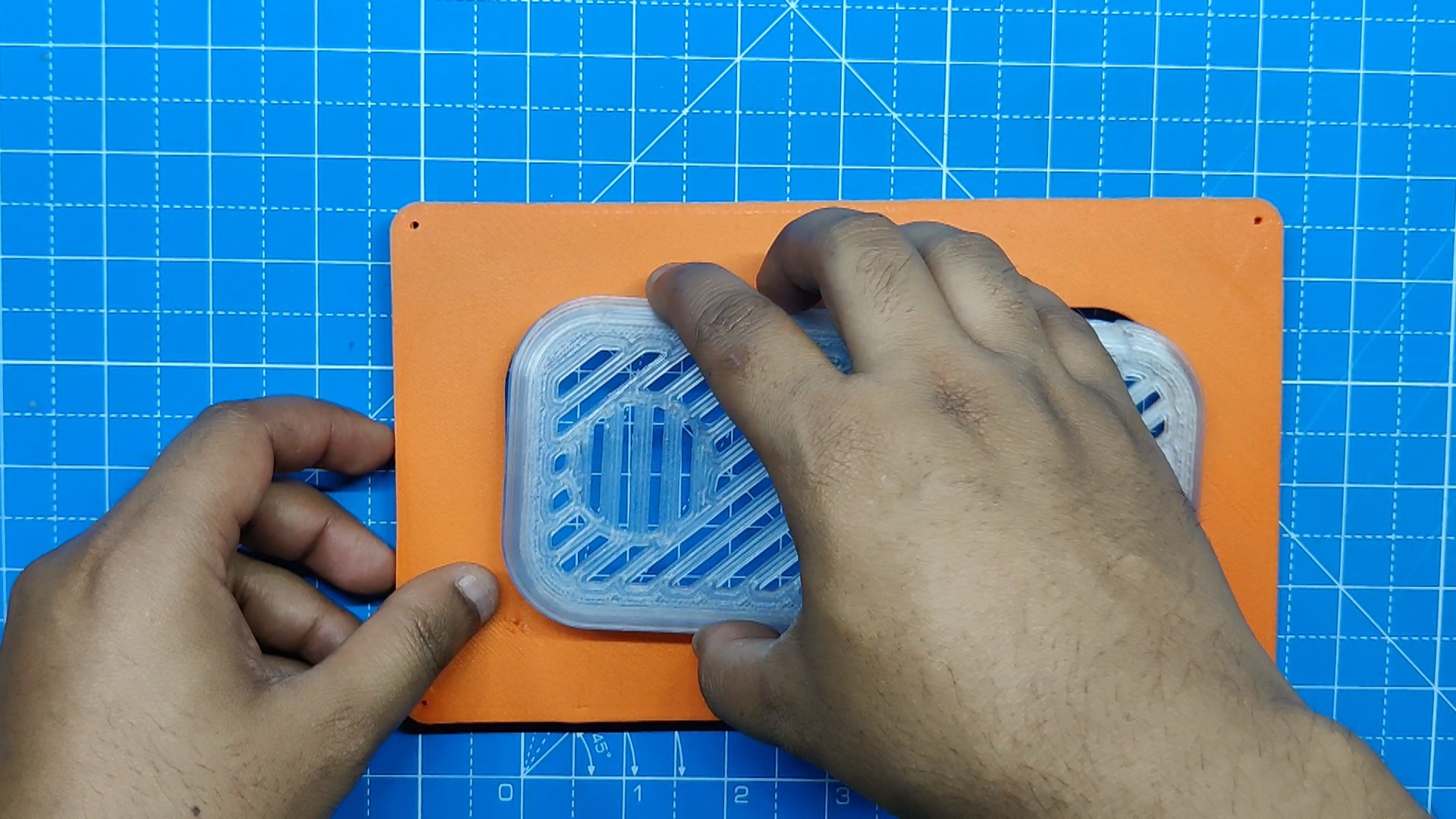
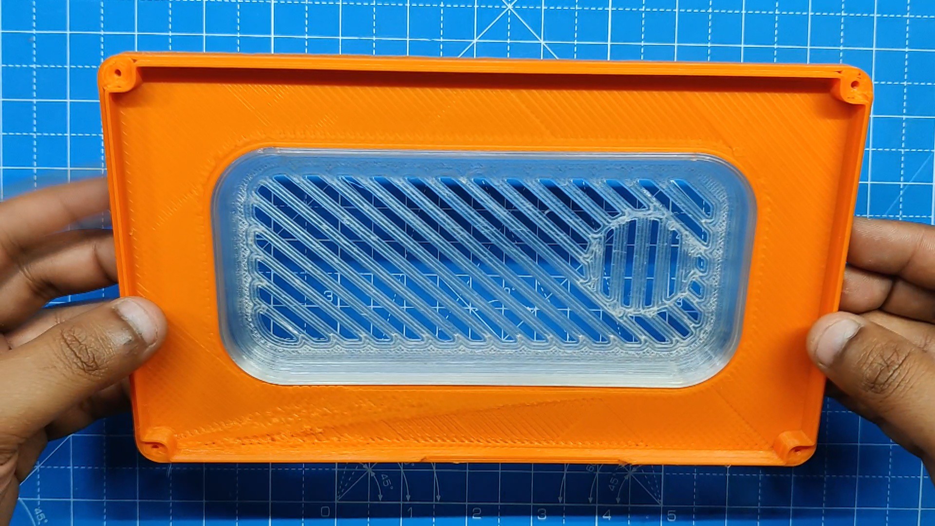
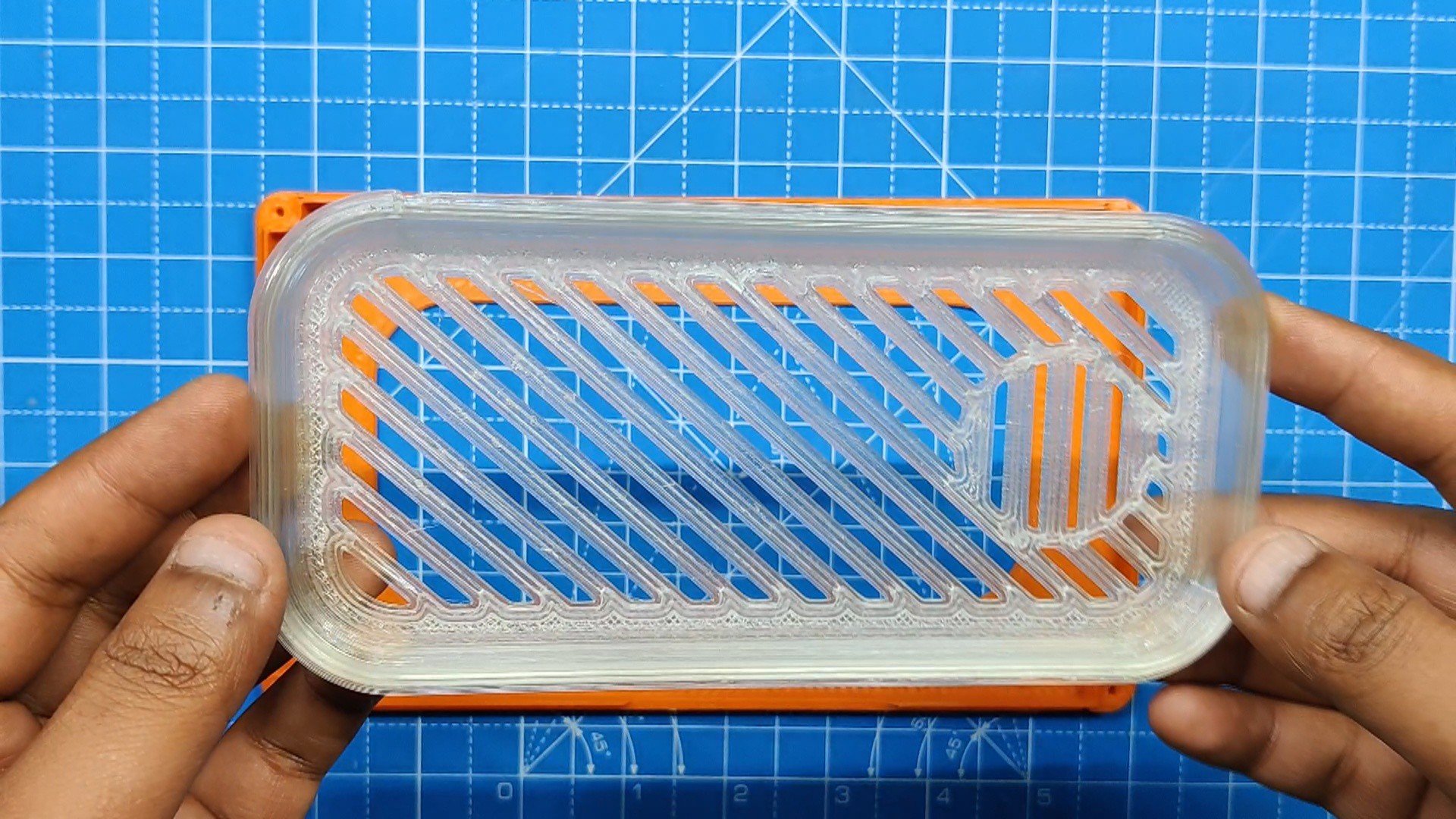
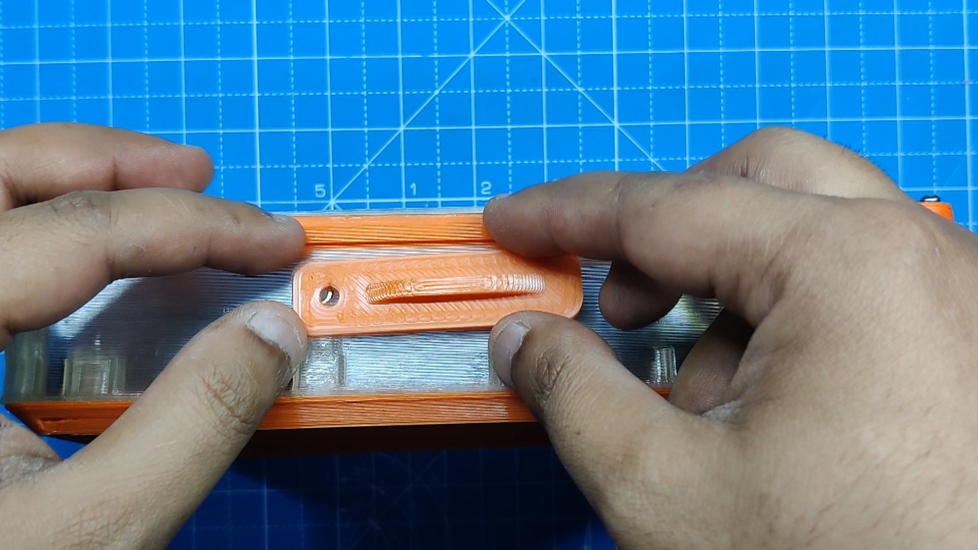
- With the lid assembly, we simply set the grill part on the back lid part and slide it into position by applying pressure to all of its edges.
- We then permanently join them together using superglue.
-
6Final Assembly
![]()
![]()
![]()
![]()
![]()
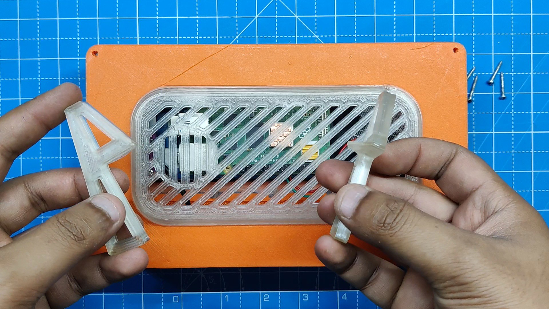
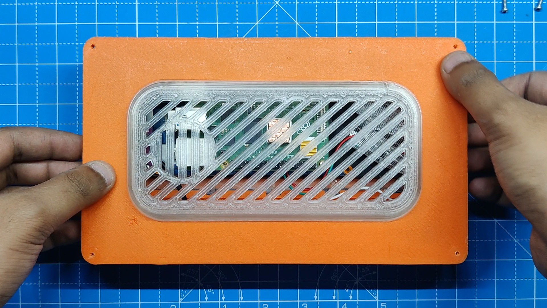
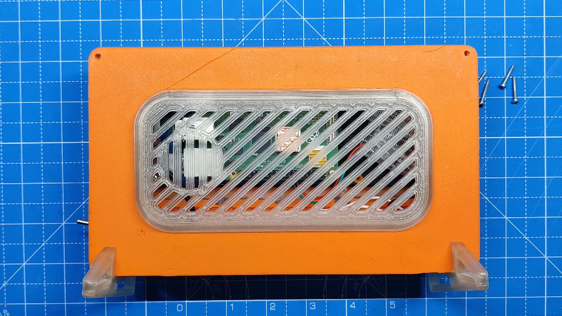
- For the final assembly, we take the lid assembly and place it on the back side of the main body.
- Next, we align the two stand parts and fasten the lid to the main body and stand part using four M2 screws.
- At this point, the IO cover was placed on the top side, and it was secured in place using the M2.5 bot.
-
7RESULT
![]()
![]()
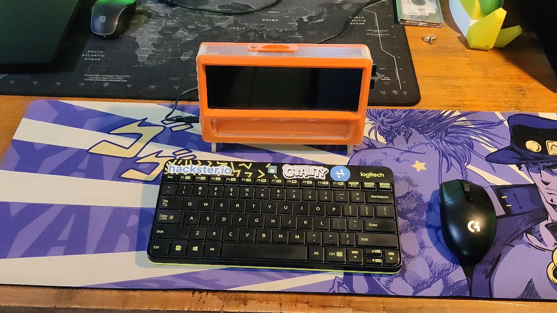
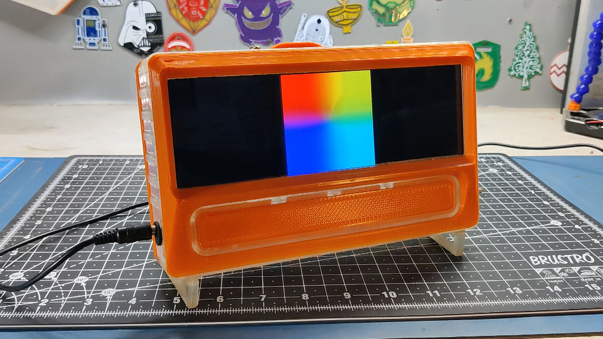
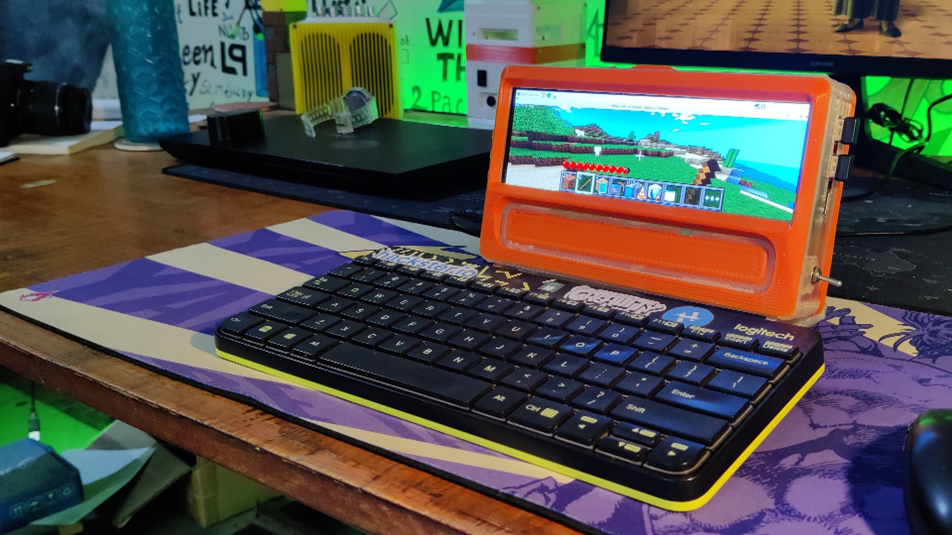
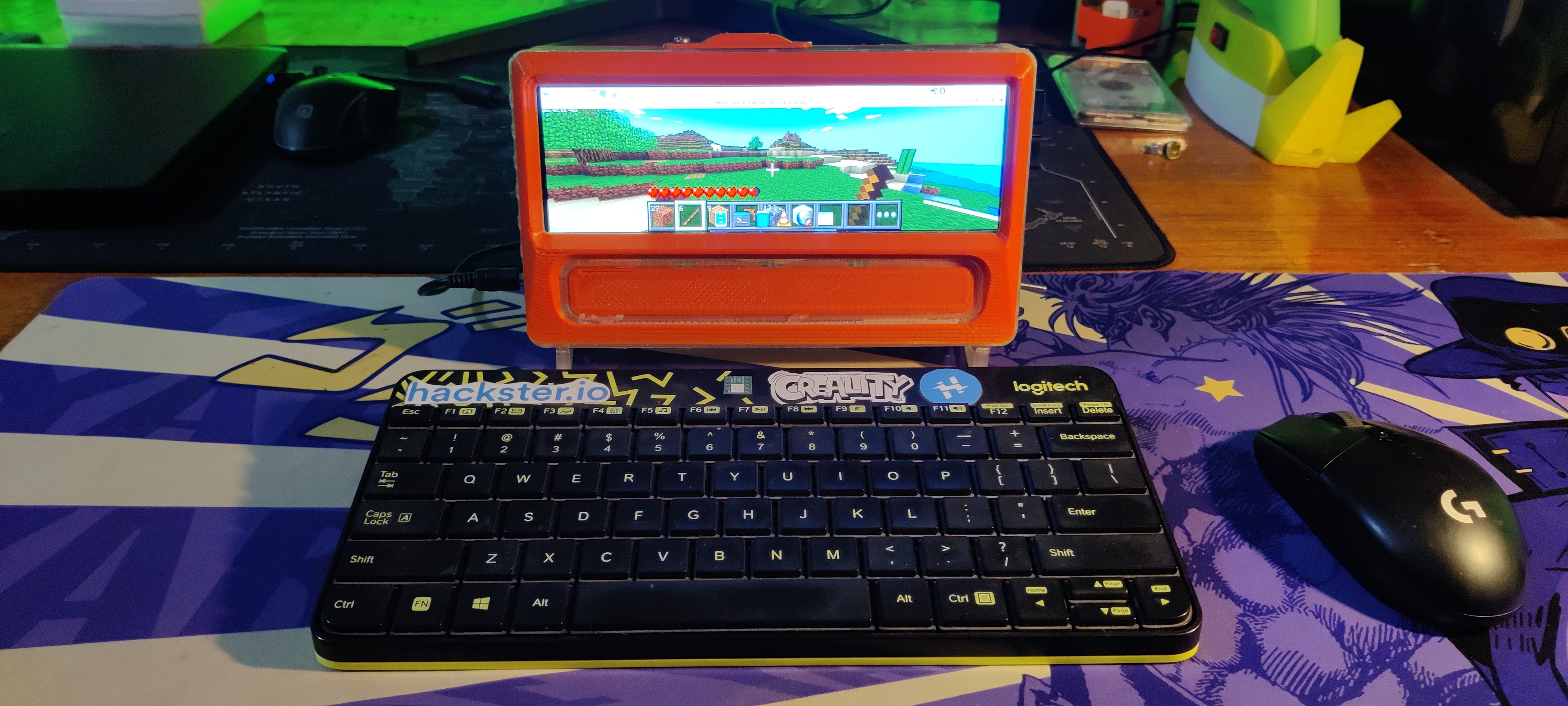
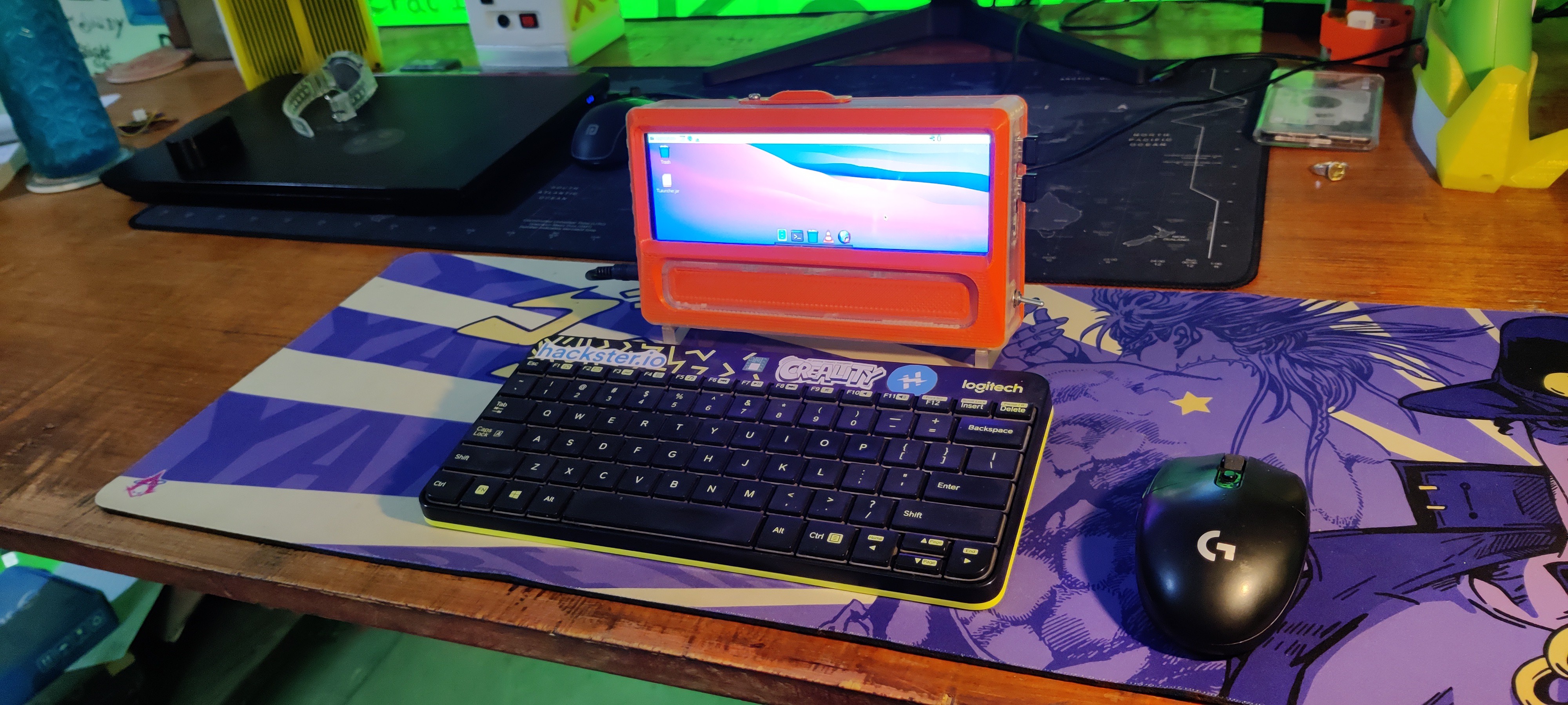
Here is the end result of this simple build: Cyber Desk version 3, a full-working PC with a cyber theme that was constructed from scratch and features a wide 7.9-inch touch display and a Raspberry Pi 4.
We used a 12V adaptor to power this setup.
-
8Minecraft Pi Edition Modded
![]()
![]()
For installing the Minecraft Pi Edition Modded, we first installed Pi-Apps, which can be installed by using the below script
wget -qO- https://raw.githubusercontent.com/Botspot/pi-apps/master/install | bash
By installing the Pi apps, we manually install the Minecraft Pi Edition modded from the game section.
Once you’ve installed it, it should automatically launch.
The modified version of Minecraft features the Minecraft Pi graphic interface, but it also has a survival mode with crafting features and improved graphics, making it far more playable than the original Pi edition.
Checkout the below link for more details.
-
9Conclusion
![]()
Although this PC performs fairly well, I would like to discuss a few issues with you all. Firstly, the arrangement lacks adequate cooling; if we are going to use this setup on a daily basis, we will need to install an effective cooling system.
Additionally, we purposefully kept this arrangement as thin as possible by excluding any internal power sources. At 45 mm in thickness overall, the device may be able to have a battery layer added to its back by carefully altering the back lid part. This would allow for the addition of a permanent internal power source.
Overall, this project turns out well since the Pi4 can handle nearly anything we throw at it, the design is extremely bright and responsive, and the end result operates as intended.
If this topic interests you, you may check out some of my previous work using the links below.
https://www.hackster.io/Arnov_Sharma_makes/cyber-py-zero-two-fdd889
https://www.hackster.io/Arnov_Sharma_makes/cyber-py-zero-one-339846
https://www.hackster.io/Arnov_Sharma_makes/power-pi-version-2-8446ef
https://www.hackster.io/Arnov_Sharma_makes/power-pi-28da7a
https://www.hackster.io/Arnov_Sharma_makes/gameboy-xl-bb64d3
A special thank to PCBWAY for supporting this project; visit them to get a wide range of services, including CNC and PCB services.
I will be back with a new project soon.
CYBER.PY Zero-Three
A cyber desk project with a Pi4 and wide LED screen jampacked in a custom 3D printed enclosure.
 Arnov Sharma
Discussions
Become a Hackaday.io Member
Create an account to leave a comment. Already have an account? Log In.