Today I worked on adding guides that allow the front/top part move up/down with respect to the bottom, while keeping it flat. We started brainstorming on this before the summer, and made a rough sketch how it could be done (shown below):
The front panel (blue PLA on the top) is mounted rigid with the PCB (dark green)
The back piece (on the bottom) is kept from falling with a screw (yellow)
When the front is pushed down, the PCB will move down and press the push button against the back piece. The front then is forced back with the help of the spring (pink) that pushes the back piece and PCB apart.
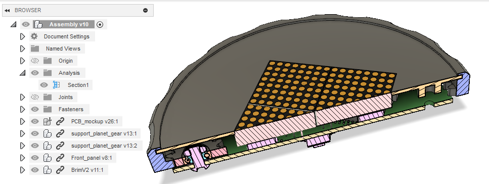
With much effort, I made a prototype of this in Fusion 360: There's likely a lot of cleaning up that needs to be done - I'm just an amateur Fusion user...
Also we'll have to duplicate this guide x4, since I just made one this time. By having 4 we should get stability when the front panel is pushed up/down (motivation: 1-2 is too few for stability, 3 ruins symmetry with the rectangular display, so 4 it is).
How to share the design? At the moment we decided to share the same Fusion 360 account, since it is impossible to collaborate otherwise.
We need to select a rotary encoder that fits with the ~7.3 mm height limitation between bottom of PCB to top of front plate.
Charging port
Should be USB-C
Discussed where the port should be. Either on the bottom => results in not being able to use it while charging. Decided it should be on the bottom, sticking out on the side.
For next time
Erasmus
Start looking at the Fusion design that Nicolas has made so far
Switching gears... from mechanical back to software.
I started a branch called multiple-timers to work on the "multiple-timers features".
This is how I am thinking of it:
The state machine has an array of timers instead of just one.
Since each timer needs to run in parallel, the "state" of the timer is recorded in the timer struct and not on the state machine. The state machine keeps track of which timer is the "current timer".
The timer being displayed is always the current timer since the display can/should display only one timer at any given time.
When a timer is displayed, there could be other timers running in the background. That means that at any point, one of the timers in the background can start RINGING. At that point, the RINGING timer becomes the current timer so it is displayed. For this, a variable in the state machine records the index of the last RINGING timer so it can be made the current timer on the "state-machine service" function
I reorganized the state machine by event first, as opposed to when it was organized by state first. I am doing this cause, since each timer has its state, each event can have an impact in one or more timers.
Since these logs have been started quite a bit after we started working on this project, I will try to summarize the progress that we have made up to now:
Software:
The code has been divided into libraries. Some libraries are platform-specific (atmega328 being the platform) and some others are platform-independent.
Platform-specific Libraries:
rotary-encoder Library: This library contains the rotary encoder functionality. Every timer you press or rotate the encoder, an interrupt gets triggered, an event gets queued, and every event is processed in the main loop.
rtc Library: This library contains the configuration of the timer interrupt that gets triggered every second.
millis Library: This library contains a function that counts milliseconds based on a second timer interrupt. This library is useful for things like "switch debouncing" or identifying double-presses on the switch.
toneAC library: This library contains tones when we create melodies for the buzzer.
display Library: [TODO]
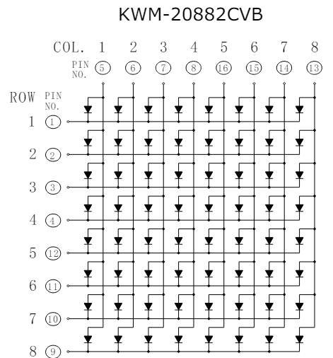
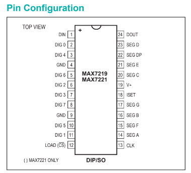
max72xx Library: [TODO]
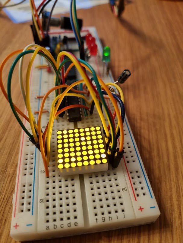
led-counter Library: This library contains some functions that allow us to test functionality with simple LEDs on our breadboards.
UART Library: This contains the UART configuration and functions to read and write to and from the serial monitor.
Platform-independent Libraries:
uint8-queue Library: This library contains the functionality to create queues of uint8_t elements. Those elements are added to the queue during the operation of the timer and processed (or dequeued) on the main loop.
state-machine Library: This library contains the state machine that defines what happens and when it happens.
str-helper Library: This library contains some functions to handle strings and was built to support the UART library.
timer Library: This library contains the timer class and its functions. The idea is that one of these objects will be created every time a new timer is set up.
Mechanics:
Our design will be very similar to the reference project. These are some of the differences:
To push the button, the user will push the whole device, unlike the reference project where the push button is part of the rotary encoder.
The brim will cover the edges of the front panel.
Electronics:
We have not started working on a PCB. All the testing is done on breadboards.
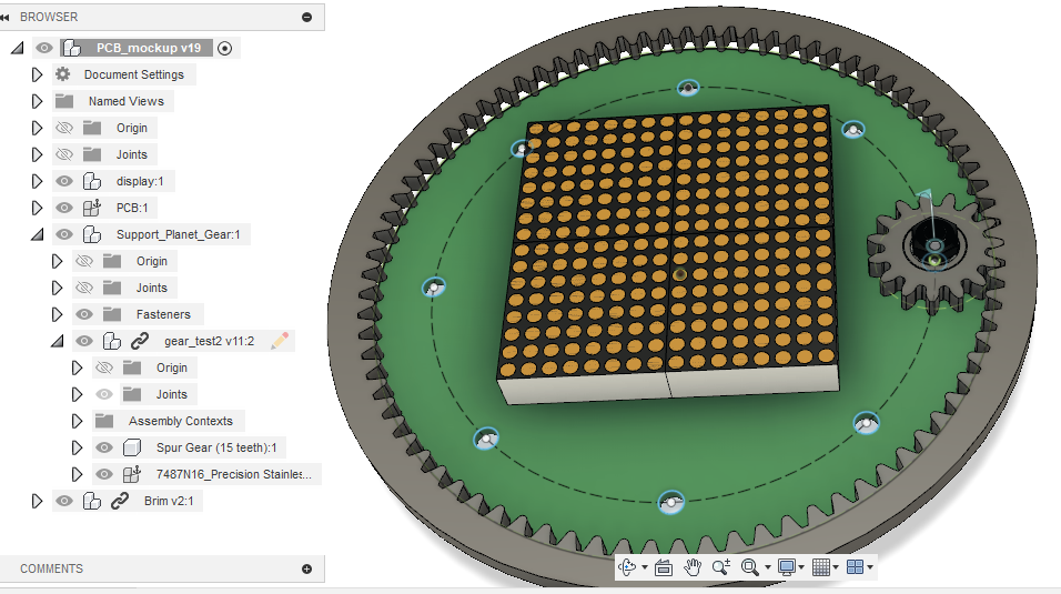
I started the design of the internal gear and the planetary gears.
Since we have an idea of how big we want the device to be (approximately 90 mm in diameter), I am starting with that constraint. Additionally, the planet gears cannot be too big since we need space for components. I am aiming for a 15-mm diameter for the planet gears.
Other parameters that I am considering:
Module = 1
Preasure angle = 20
Ring gear number of teeth = 80
Planet Gears number of teeth = 15
Backlash = 0.1 (I am adding this because the gears will be 3D printed.)
Gear thickness: 4 mm (as per the width of the bearing that we ordered).
Next challenge: define the joints in Fusion 360 assembly so the planet gears and ring gear work without a sun gear or planet gear holder.
The dial will drive the rotary encoder using a "planetary gear" type setup. One of the planet gears will have the encoder as the shaft but the other two gears, which work as support, will rotate freely over bearings. The free-rotating gears will be fixed to the PCB by a M3 screw and separated from it by a washer.
These are the requirements that I was considering:
The outer diameter needs to be small enough so it leaves enough space for the 3d printed gears to be strong enough.
The inner diameter needs to be 3mm so it fits an M3 screw.
The width needs to be small enough so it leaves space for a washer and a nut in the space between the PCB and the top lid of the device.
I ended up settling for the following open bearings with OD: 8mm, ID: 3mm, width: 3mm
 Nicolas Perozzi
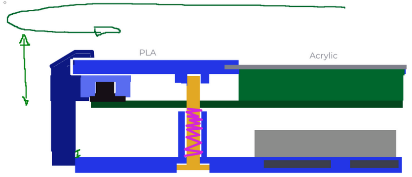
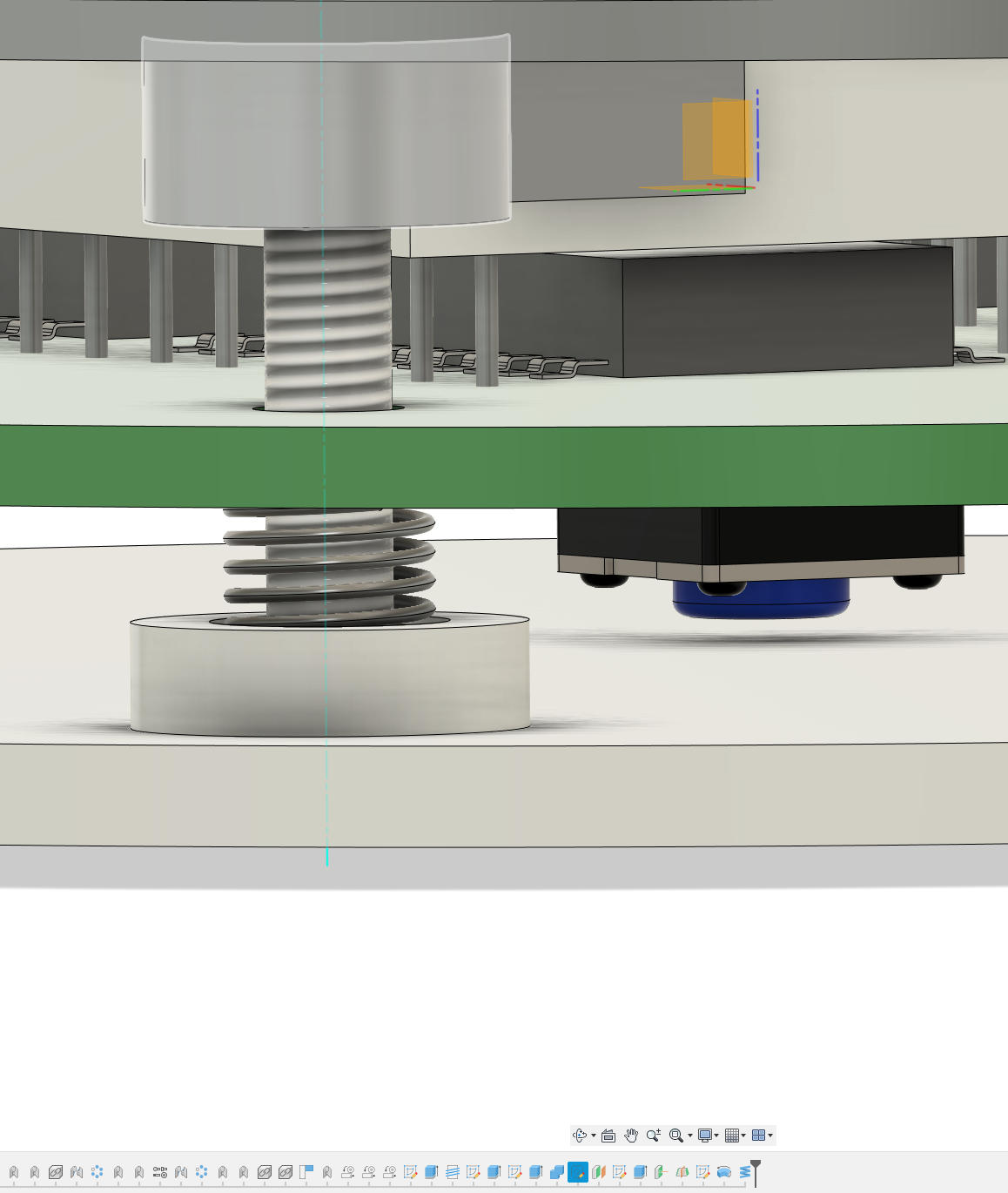 There's likely a lot of cleaning up that needs to be done - I'm just an amateur Fusion user...